Transducer Electronic Data Sheets: Anywhere, Anytime, Anyway


Abstract
:1. Introduction
- TEDS are more sustainable because they are dematerialized and do not waste paper.
- TEDS are more adaptable as long as they are writable. This allows the storage of dynamic data such as calibration tables and maintenance logs.
- TEDS are more traceable because they can be embedded on the transducer, thus creating a one-to-one relationship. For new devices, this requires including the TEDS into the manufacturing process; for legacy devices, this requires making modifications to the existing transducer, such as putting the TEDS inside the transducer case or inside the transducer plug.
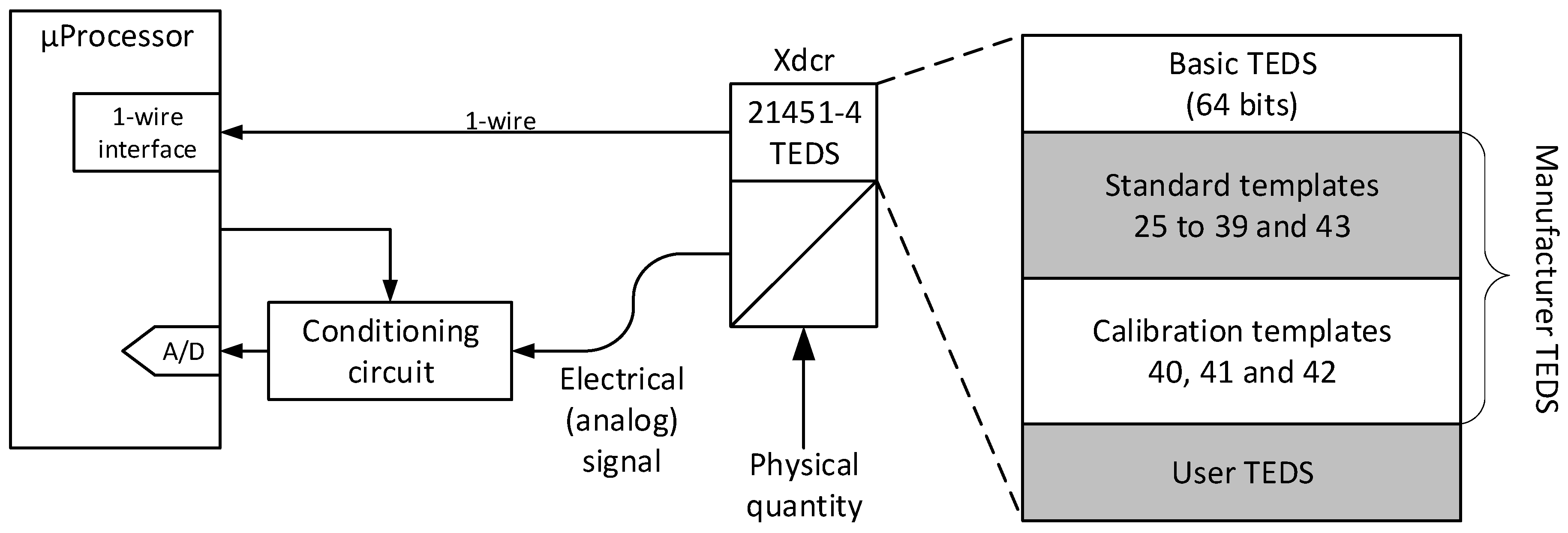
2. ISO/IEC/IEEE 21451-4
- Basic TEDS (mandatory, read-only, 64 bits length): Contains the transducer ID composed by the manufacturer ID (14 bits), model number (15 bits), version letter (5 bits), version number (6 bits), and serial number (24 bits). The first field (the manufacturer ID) is managed centrally by the IEEE [17], all the other fields are managed by the manufacturer itself. Altogether, the five fields provide a unique identifier.
- Manufacturer TEDS (optional, variable length): Describes the technical characteristics of the transducer and provides information about its calibration status. The data are organized in pre-defined templates numbered from 25 to 43. Standard templates 25–39 and 43 are used to specify common types of transducers, namely: charge accelerometer/force transducers, voltage output sensors, current-loop transmitters, resistance sensors, bridge sensors, linear/rotary variable differential transformers (LVDT/RVDT), strain gauges, thermocouples, resistance temperature detectors (RTD), thermistors, and potentiometric voltage dividers. Calibration templates 40, 41, and 42 are used to characterize the transducer in terms of calibration curve and frequency response.
- User TEDS (optional, variable length): The user can add free data at the end of the TEDS. These extra data are format free and application specific.
3. Related Work
- Proposal of easier ways to store and access TEDS tables, which do not require wiring, circuitry, or power supply.
- Presentation of desktop and mobile tools to access TEDS content at the laboratory and in the field.
- Proposal of a new template to describe frequency–time sensors.
4. TEDS Dissemination
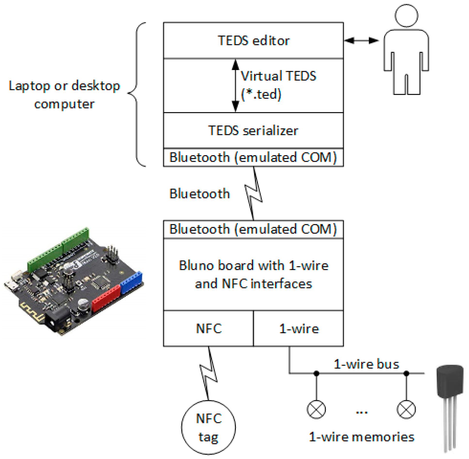
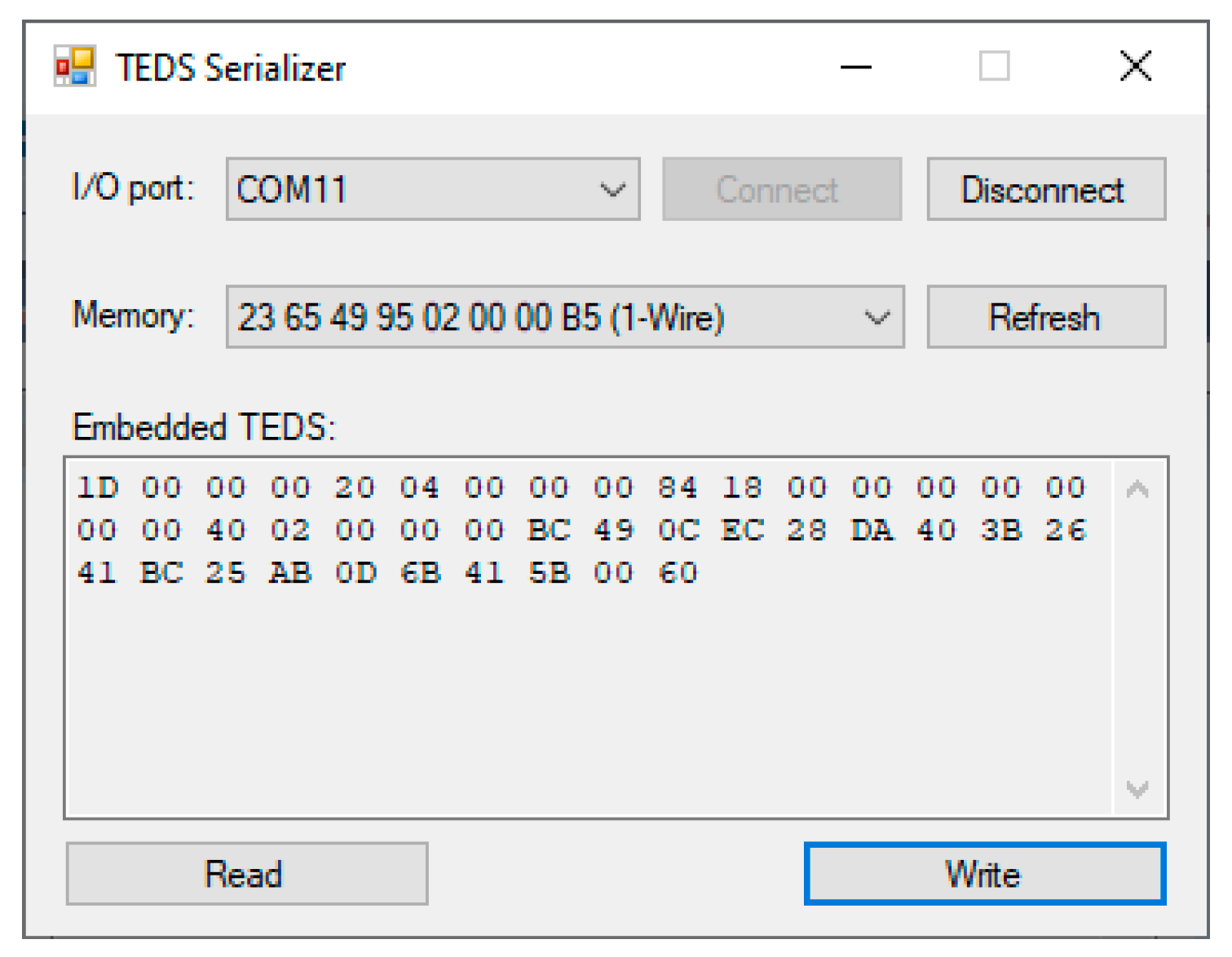
4.1. Embedded TEDS
4.2. Near TEDS
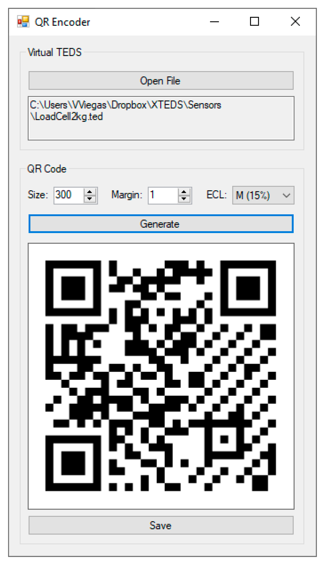
4.3. Printed TEDS
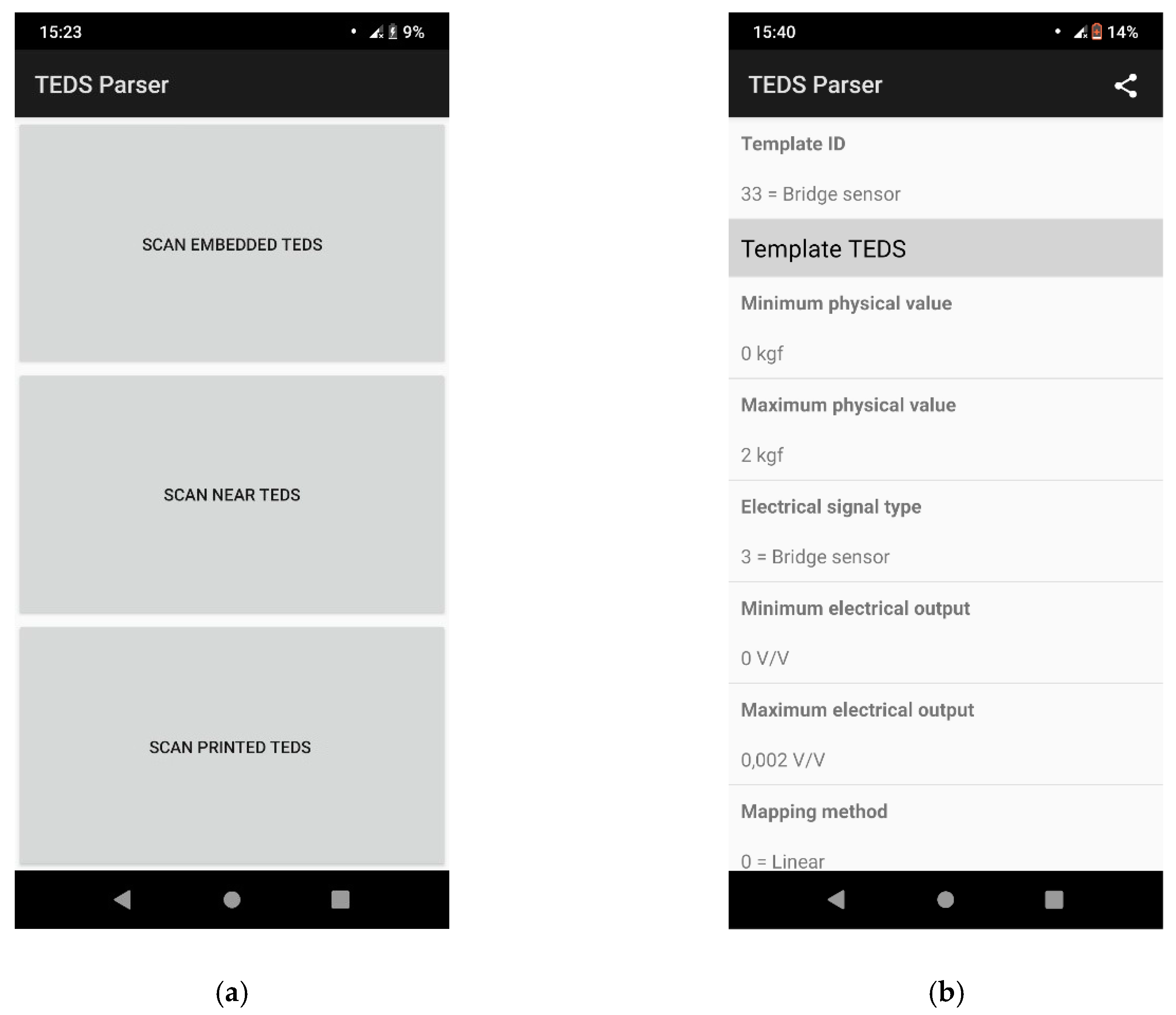
4.4. Mobile Parser
- Embedded TEDS: The parser connects to the Bluno-based TEDS reader (using a Bluetooth-emulated COM) and gets a list of connected one-wire memories. For a given memory, the embedded TEDS are serialized, parsed, and presented as human-readable text.
- Near TEDS: The parser searches for an NFC tag filled with TEDS data. If it succeeds, data are read, parsed, and presented to the user as before.
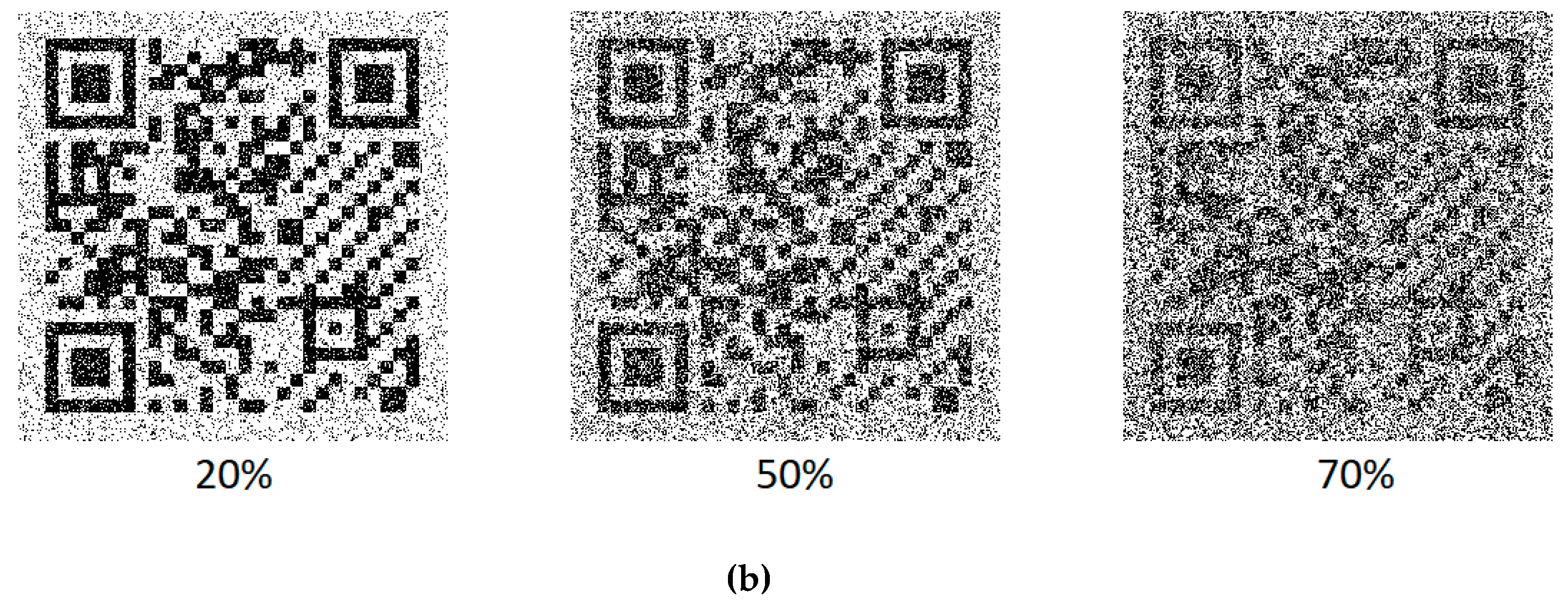
- Printed TEDS: The parser opens the cam and waits for the user to take a snapshot of a valid QR code. The image is decoded, and the resulting data are parsed and presented to the user as before.
5. Experimental Results
6. Enhancements to the ISO/IEC/IEEE 21451-4 Standard
- Measurement: gives information about the physical quantity that is being measured and its expected range.
- Electrical signal output: describes the electrical signal used as the primary output of the sensor. In the present case, a voltage signal with two amplitude levels is used. Information about the amplitude levels is useful to detect edges, while information about the frequency range is useful to choose an adequate clock to measure time.
- Time signal output: explains how the timing information is encoded in the electrical signal. Four options are available: time the signal passes in the low level (case 0), time the signal passes in the high level (case 1), period (case 2), and duty cycle (case 3). It is assumed that the measurand maps linearly to the timing quantity.
- Calibration information: provides basic information about the calibration status of the sensor (inherit from existing templates).
- Miscellaneous: provides basic information about the measurement location (inherit from existing templates).
7. Conclusions
Author Contributions
Funding
Conflicts of Interest
References
- Dewey, F.R. A Complete Guide to Data Sheets. Sensors Magazine. 1998. Available online: http://www.algrel.com/AllegroPDF/Allegro-1.pdf (accessed on 6 September 2019).
- Potter, D. Smart plug and play sensors. IEEE Instrum. Meas. Mag. 2002, 5, 28–30. [Google Scholar] [CrossRef]
- Boecking, B. Plug-and-Play Sensors Make Big Promises. ISA InTech Magazine. 2003. Available online: https://www.isa.org/standards-and-publications/isa-publications/intech-magazine/2003/may/sensors-on-the-rise-plug-and-play-sensors-make-big-promises/ (accessed on 6 September 2019).
- TEDS. This Is How It Works. Available online: https://www.hbm.com/en/6258/article-teds-for-cost-savings-short-setup-times-and-application-safety/ (accessed on 6 September 2019).
- Meijer, G.; Pertijs, M.; Makinwa, K. Chapter 2—Calibration and Self-Calibration of Smart Sensors, In Smart Sensor Systems: Emerging Technologies and Applications; John Wiley & Sons: Edison, NJ, USA, 2014; ISBN 978-0-470-68600-3. [Google Scholar]
- Hunter, G.W.; Stetter, J.R.; Hesketh, P.J.; Liu, C.-C. Smart Sensor Systems. Electromech. Soc. Interface 2010, 19, 29–34. Available online: https://www.electrochem.org/dl/interface/wtr/wtr10/wtr10_p029-034.pdf (accessed on 6 September 2019). [CrossRef]
- Mathas, C. Smart Sensors—Not Only Intelligent, but Adaptable. Available online: https://www.digikey.com/en/articles/techzone/2011/sep/smart-sensors---not-only-intelligent-but-adaptable (accessed on 6 September 2019).
- Frank, R. Understanding Smart Sensors, 3rd ed.; Artech House: Morwood, MA, USA, 2013; ISBN 978-1-60807-507-2. [Google Scholar]
- IEEE Standard 1451.4–IEEE Standard for a Smart Transducer Interface for Sensors and Actuators–Mixed-Mode Communication Protocols and Transducer Electronic Data Sheets (TEDS) Formats; IEEE Instrumentation & Measurement Society: New York, NY, USA, 2004; ISBN 0-7381-4007-4.
- Betts, B. Smart sensors—New standard could save lives and money. IEEE Spectrum, 2006. [Google Scholar]
- Mark, J.; Hufnagel, P. What is 1451.4, What Are Its Uses and How Does It Work? Available online: http://standards.ieee.org/develop/regauth/tut/1451d4.pdf (accessed on 6 September 2019).
- IEEE 1451.4 Sensor Templates Overview. Available online: http://www.ni.com/white-paper/3468/en/ (accessed on 6 September 2019).
- Romanchik, D. Tips for Using TEDS Sensors, EDN Network. 2004. Available online: http://www.edn.com/design/test-and-measurement/4387035/Tips-for-using-TEDS-sensors (accessed on 6 September 2019).
- Jevtic, N.; Drndarevic, V. Development of smart transducers compliant with the IEEE 1451.4 standard. In Proceedings of the 8th IEEE International Symposium on Instrumentation and Control Technology (ISICT), London, UK, 11–13 July 2012. [Google Scholar] [CrossRef]
- Song, E.Y.; Lee, K. Understanding IEEE 1451—Networked smart transducer interface standard. IEEE Instrum. Meas. Mag. 2008, 11, 11–17. [Google Scholar] [CrossRef]
- Wobschall, D. Networked sensor monitoring using the universal IEEE 1451 standard. IEEE Instrum. Meas. Mag. 2008, 11, 18–22. [Google Scholar]
- IEEE Standards Association. Available online: https://standards.ieee.org/products-services/regauth/manid/index.html (accessed on 6 September 2019).
- Creating Virtual TEDS. Available online: http://www.ni.com/example/26498/en/ (accessed on 6 September 2019).
- Reading Smart TEDS Sensors and Virtual TEDS Files in LabVIEW. Available online: http://www.ni.com/example/27195/en/ (accessed on 6 September 2019).
- Ulivieri, N.; Distante, C.; Luca, T.; Rocchi, S.; Siciliano, P. IEEE1451.4: A way to standardize gas sensor. Sens. Actuators B: Chem. 2006, 114, 141–151. [Google Scholar] [CrossRef]
- Corotinschi, G.; Găitan, V.G. The development of IoT applications using old hardware equipment and virtual TEDS. In Proceedings of the IEEE International Conference on development and application systems (DAS), Suceava, Romania, 19–21 May 2016. [Google Scholar] [CrossRef]
- Hernández-Rojas, D.L.; Fernández-Caramés, T.M.; Fraga-Lamas, P.; Escudero, C.J. A Plug-and-Play Human-Centered Virtual TEDS Architecture for the Web of Things. Sensors 2018, 18, 2052. Available online: https://www.mdpi.com/1424-8220/18/7/2052 (accessed on 9 September 2019). [CrossRef] [PubMed]
- Morello, R. Use of TEDS to Improve Performances of Smart Biomedical Sensors and Instrumentation. IEEE Sens. J. 2015, 15, 2497–2504. [Google Scholar] [CrossRef]
- Mitterer, T.; Gietler, H. Lisa-Marie Faller, Huber Zangl, Artificial Landmarks for Trusted Localization of Autonomous Vehicles Based on Magnetic Sensors. Sensors 2019, 19, 813. [Google Scholar] [CrossRef] [PubMed]
- Ajigboye, O.S.; Danas, K. Towards semantics in wearable sensors: The role of transducers electronic data sheets (TEDS) ontology in sensor networks. In Proceedings of the IEEE 18th International Conference on e-Health Networking, Applications and Services (Healthcom), Munich, Germany, 14–16 September 2016. [Google Scholar] [CrossRef]
- Amin, F.; Zubair, M. Energy-efficient clustering scheme for multihop wireless sensor network (ECMS). In Proceedings of the 17th IEEE International Multi Topic Conference 2014, Karashi, Pakistan, 8–10 December 2014. [Google Scholar] [CrossRef]
- Jevtic, N.; Drndarevic, V. Plug and Play Geiger-Muller Detector for Environmental Monitoring. Instrum. Sci. Technol. 2014, 43, 222–243. [Google Scholar] [CrossRef]
- Kim, J.-D.; Kim, D.-J.; Byun, H.-G.; Ham, Y.-K.; Jung, W.-S.; Han, D.-W.; Park, J.-S.; Lee, H.-L. The definition of basic TEDS of IEEE 1451.4 for sensors for an electronic tongue and the proposal of new template TEDS for electrochemical devices. Talanta 2007, 71, 1642–1651. [Google Scholar] [CrossRef] [PubMed]
- Linke, B. Tutorial 1796—Overview of 1-wire technology and its use, maxim integrated. 2008. Available online: http://pdfserv.maximintegrated.com/en/an/AN1796.pdf (accessed on 6 September 2019).
- How Do I Install the TEDS Library into LabVIEW? Available online: https://knowledge.ni.com/KnowledgeArticleDetails?id=kA00Z0000019LmDSAU&l=pt-PT (accessed on 10 September 2019).
- Bluno—An Arduino Bluetooth 4.0 (BLE) Board. Available online: https://www.dfrobot.com/product-1044.html (accessed on 6 September 2019).
- OneWire Library. Available online: https://www.pjrc.com/teensy/td_libs_OneWire.html (accessed on 6 September 2019).
- What is NFC. Available online: https://www.shopnfc.com/en/content/9-what-is-nfc (accessed on 6 September 2019).
- Adafruit PN532 RFID/NFC Breakout and Shield. Available online: https://learn.adafruit.com/adafruit-pn532-rfid-nfc/overview (accessed on 6 September 2019).
- Answers to Your Questions about the QR Code. Available online: https://www.qrcode.com/en/ (accessed on 6 September 2019).
- Viegas, V.; Pereira, J.M.D.; Girão, P.S.; Postolache, O. Transducer Electronic Data Sheets: Why Not Print Them? In Proceedings of the 2014 International Conference and Exposition on Electrical and Power Engineering (EPE), Iasi, Romania, 16–17 October 2014. [Google Scholar]
- ZXingNET. Available online: https://archive.codeplex.com/?p=zxingnet (accessed on 6 September 2019).
- Quirc. Available online: https://github.com/dlbeer/quirc (accessed on 6 September 2019).
- ZBar Bar Code Reader. Available online: http://zbar.sourceforge.net/ (accessed on 6 September 2019).
- Xamarin.Android. Available online: https://docs.microsoft.com/en-us/xamarin/android/ (accessed on 6 September 2019).
- Yurish, S.Y. Sensors and transducers: frequency output versus voltage output. Sens. Transducers J. 2004, 49, 302–305. [Google Scholar]
- LIDAR-Lite v3. Available online: https://buy.garmin.com/en-US/US/p/557294/pn/010-01722-00 (accessed on 6 September 2019).
- MAX666/7. Available online: https://datasheets.maximintegrated.com/en/ds/MAX6666-MAX6667.pdf (accessed on 6 September 2019).


| Section | Parameter | Bits | Value |
|---|---|---|---|
| Basic | Manufacturer ID | 14 | tbd 1 |
| Model number | 15 | 505 | |
| Version letter | 5 | H | |
| Version number | 6 | 2 | |
| Serial number | 24 | tbd 2 | |
| Template | Template ID | 8 | 33 |
| Select case (physical measurand) | 6 | kgf | |
| Minimum physical value | 32 | 0 | |
| Maximum physical value | 32 | +2 | |
| Transducer electrical signal type | --- | Bridge sensor | |
| Select case (full-scale electrical value precision) | 2 | 2 | |
| Minimum electrical output | 32 | 0 | |
| Maximum electrical output | 32 | +2 mV/V | |
| Mapping method | --- | Linear | |
| Bridge type | 2 | Full | |
| Bridge element impedance | 18 | 350 Ω | |
| Response time | 6 | 1 s | |
| Excitation level, nominal | 9 | 10 | |
| Excitation level, minimum | 9 | 0 | |
| Excitation level, maximum | 9 | 15 | |
| Calibration date | 16 | 01-06-2019 | |
| Calibration initials | 15 | VV | |
| Calibration period | 12 | 365 days | |
| Measurement location ID | 11 | 21 |
| Condition | Read Successful? |
|---|---|
| NFC tag in line of sight | Yes 1 |
| NFC tag inside plastic enclosure | Yes 1 |
| NFC tag covered by aluminum tape | No |
| NFC tag inside metallic enclosure | No |
| Section | Parameter | Bits | Datatype | Unit | |
|---|---|---|---|---|---|
| ID | Template ID | 8 | Integer | --- | |
| Measurement | Select case-physical measurand | 6 | Selector | --- | |
| Minimum physical value | 32 | Single | Various 1 | ||
| Maximum physical value | 32 | Single | Various 1 | ||
| Electrical signal output | Transducer electrical signal type | --- | Assume “voltage” | --- | |
| Low level | 9 | ConRes (0 to +10.2, step 0.02) | V | ||
| High level | 9 | ConRes (0 to +10.2, step 0.02) | V | ||
| Minimum frequency | 7 | ConRelRes (1 to 9.48 GHz, ±10%) | Hz | ||
| Maximum frequency | 7 | ConRelRes (1 to 9.48 GHz, ±10%) | Hz | ||
| Response time | 6 | ConRelRes (1 × 10⁻⁶ to 7.9, ±15%) | s | ||
| Time signal output | Select case-signal type | 2 | Selector | --- | |
| Case 0 (low time) | Minimum timing value | 32 | Single | s | |
| Maximum timing value | 32 | Single | s | ||
| Case 1 (high time) | Minimum timing value | 32 | Single | s | |
| Maximum timing value | 32 | Single | s | ||
| Case 2 (period) | Minimum timing value | 32 | Single | s | |
| Maximum timing value | 32 | Single | s | ||
| Case 3 (duty cycle) | Minimum timing value | 32 | Single | s/s | |
| Maximum timing value | 32 | Single | s/s | ||
| Mapping method | --- | Assume “linear” | --- | ||
| Calibration information | Calibration date | 16 | Date | --- | |
| Calibration initials | 15 | Chr5 | --- | ||
| Calibration period | 12 | UInt | days | ||
| Misc. | Measurement location ID | 11 | UInt | --- | |
| Section | Parameter | Bits | Value | |
|---|---|---|---|---|
| Basic | Manufacturer ID | 14 | tbd 1 | |
| Model number | 15 | tbd 1 | ||
| Version letter | 5 | tbd 1 | ||
| Version number | 6 | 3 | ||
| Serial number | 24 | tbd 2 | ||
| ID | Template ID | 8 | tbd 3 | |
| Measurement | Select case-physical measurand | 6 | m | |
| Minimum physical value | 32 | 0 | ||
| Maximum physical value | 32 | 40 | ||
| Electrical signal output | Transducer electrical signal type | --- | Assume “voltage” | |
| Low level | 9 | 0 | ||
| High level | 9 | 5 | ||
| Minimum frequency | 7 | 0 | ||
| Maximum frequency | 7 | 1 kHz | ||
| Response time | 6 | 10 μs | ||
| Time signal output | Select case-signal type | 2 | 0 | |
| Case 0 (low time) | Minimum timing value | 32 | 10 μs | |
| Maximum timing value | 32 | 40 ms | ||
| Case 1 (high time) | Minimum timing value | 32 | --- | |
| Maximum timing value | 32 | --- | ||
| Case 2 (period) | Minimum timing value | 32 | --- | |
| Maximum timing value | 32 | --- | ||
| Case 3 (duty cycle) | Minimum timing value | 32 | --- | |
| Maximum timing value | 32 | --- | ||
| Mapping method | --- | Assume “linear” | ||
| Calibration information | Calibration date | 16 | 01-06-2019 | |
| Calibration initials | 15 | VV | ||
| Calibration period | 12 | 365 days | ||
| Misc. | Measurement location ID | 11 | 21 | |
| Section | Parameter | Bits | Value | |
|---|---|---|---|---|
| Basic | Manufacturer ID | 14 | tbd 1 | |
| Model number | 15 | tbd 1 | ||
| Version letter | 5 | tbd 1 | ||
| Version number | 6 | 3 | ||
| Serial number | 24 | tbd 2 | ||
| ID | Template ID | 8 | tbd 3 | |
| Measurement | Select case-physical measurand | 6 | °C | |
| Minimum physical value | 32 | −40 | ||
| Maximum physical value | 32 | +125 | ||
| Electrical signal output | Transducer electrical signal type | --- | Assume “voltage” | |
| Low level | 9 | 0 | ||
| High level | 9 | 5 | ||
| Minimum frequency | 7 | 233.15 Hz 4 | ||
| Maximum frequency | 7 | 398.15 Hz 4 | ||
| Response time | 6 | 5 s 5 | ||
| Time signal output | Select case-signal type | 2 | 2 | |
| Case 0 (low time) | Minimum timing value | 32 | --- | |
| Maximum timing value | 32 | --- | ||
| Case 1 (high time) | Minimum timing value | 32 | --- | |
| Maximum timing value | 32 | --- | ||
| Case 2 (period) | Minimum timing value | 32 | 2.512 ms | |
| Maximum timing value | 32 | 4.289 ms | ||
| Case 3 (duty cycle) | Minimum timing value | 32 | --- | |
| Maximum timing value | 32 | --- | ||
| Mapping method | --- | Assume “linear” | ||
| Calibration information | Calibration date | 16 | 01-06-2019 | |
| Calibration initials | 15 | VV | ||
| Calibration period | 12 | 365 days | ||
| Misc. | Measurement location ID | 11 | 21 | |
© 2019 by the authors. Licensee MDPI, Basel, Switzerland. This article is an open access article distributed under the terms and conditions of the Creative Commons Attribution (CC BY) license (http://creativecommons.org/licenses/by/4.0/).
Share and Cite
Viegas, V.; Postolache, O.; Dias Pereira, J.M. Transducer Electronic Data Sheets: Anywhere, Anytime, Anyway. Electronics 2019, 8, 1345. https://doi.org/10.3390/electronics8111345
Viegas V, Postolache O, Dias Pereira JM. Transducer Electronic Data Sheets: Anywhere, Anytime, Anyway. Electronics. 2019; 8(11):1345. https://doi.org/10.3390/electronics8111345
Chicago/Turabian StyleViegas, Vítor, Octavian Postolache, and J.M. Dias Pereira. 2019. "Transducer Electronic Data Sheets: Anywhere, Anytime, Anyway" Electronics 8, no. 11: 1345. https://doi.org/10.3390/electronics8111345