Soft Elbow Exoskeleton for Upper Limb Assistance Incorporating Dual Motor-Tendon Actuator


 , and
, and
Abstract
:1. Introduction
2. Soft Elbow Exoskeleton and Motor-Tendon Actuator Design
2.1. Fabric-Based Soft Elbow Exoskeleton Design
2.2. Motor-Tendon Actuation Design
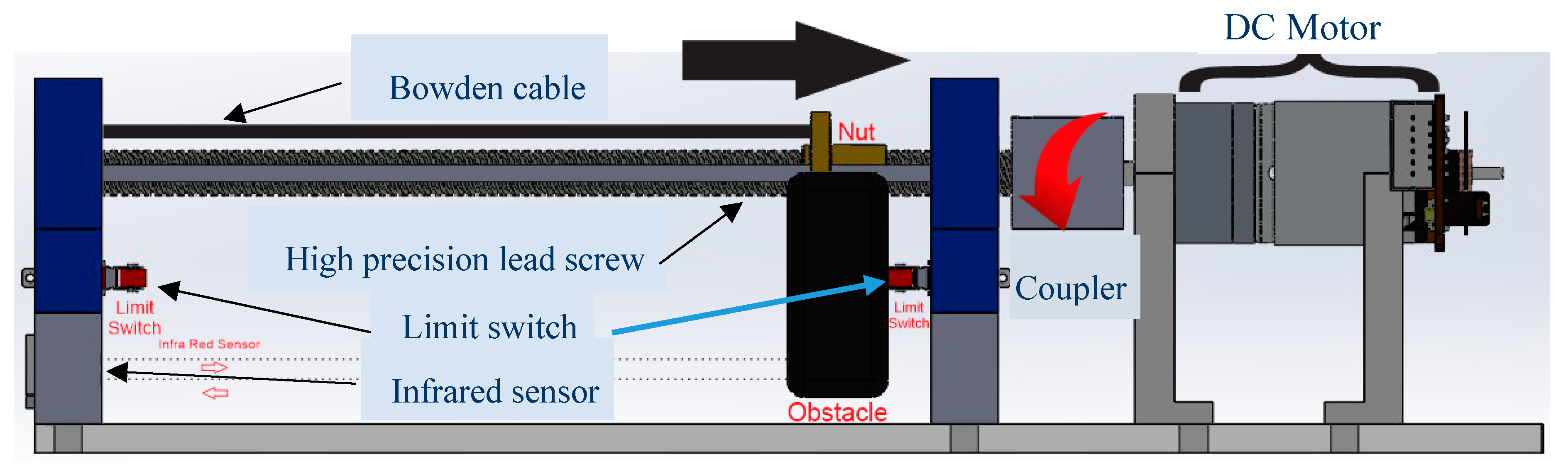
2.2.1. Components
2.2.2. Infrared Sensor Calibration and Filter
3. Two DOF Soft Elbow Exoskeleton and Control
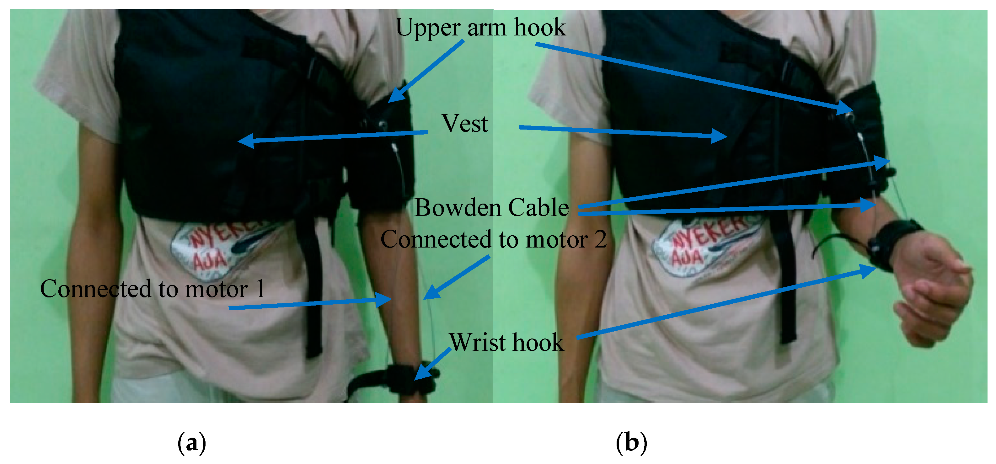
3.1. Wearable Soft Elbow Exoskeleton System
3.1.1. Vest, Arm, and Wrist Hook
3.1.2. Motor-Tendon Actuator with Case
3.2. PI Control
3.2.1. PID Tuner
3.2.2. Proportional-Integral (PI) Control
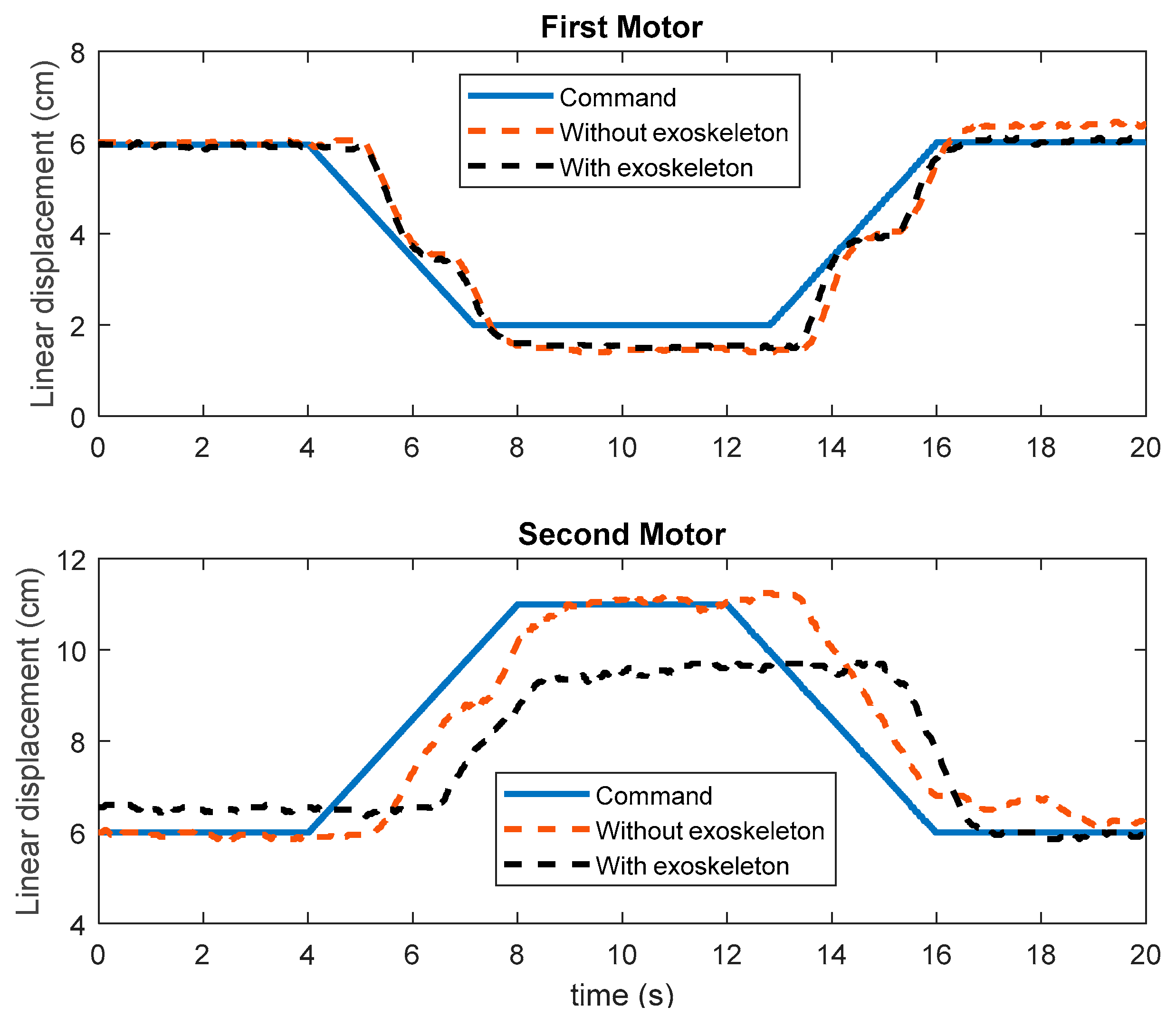
4. Result and Discussion
5. Conclusions
Supplementary Materials
Author Contributions
Funding
Conflicts of Interest
Appendix A

| Specification | Value |
|---|---|
| Upper arm and wrist hook | Polylactic acid (PLA) |
| Vest material | Polyester |
| Vest mass and hooks | 358 g |
| Dual motor-tendon actuator | 1655 g |
| Dual motor-tendon actuator | 29 × 9.5 × 21 cm |
| Bowden cable length of the first motor and second motor | 70 cm |
| Input voltage | 12 V DC |
| Microcontroller | Arduino MEGA 2560 |
| Maximum of the actuator linear displacement | 12.5 cm |
| Feedback | Infrared sensor |
| Control | Proportional-Integral compensator |
| Feedback | Infrared sensor |
| Motor type | Brushed DC motor |
| Mechanical drive system | Precision lead screw |
| Number of DOF | Two (flexion/extension and pronation/supination) |
| Limit or home sensing | Limit switch |
| Maximum pull force of the first motor | 33 N |
| Maximum pull force of the second motor | 31 N |
| Input sensor as a command | potentiometer |
| Communication interface | USB |
| ROM for flexion/extension | 90°–157° |
| ROM for pronation | 0°–19° |
| ROM for supination | 0°–18° |
References
- Chiaradia, D.; Xiloyannis, M.; Solazzi, M.; Masia, L.; Frisoli, A. Comparison of a Soft Exosuit and a Rigid Exoskeleton in an Assistive Task. In Proceedings of the Wearable Robotics: Challenges and Trends; Carrozza, M.C., Micera, S., Pons, J.L., Eds.; Springer International Publishing: Cham, Switzerland, 2019; pp. 415–419. [Google Scholar]
- Nadas, I.; Pisla, D.; Ceccarelli, M.; Vaida, C.; Gherman, B.; Tucan, P.; Carbone, G. Design of Dual-Arm Exoskeleton for Mirrored Upper Limb Rehabilitation. In Proceedings of the New Trends in Medical and Service Robotics; Carbone, G., Ceccarelli, M., Pisla, D., Eds.; Springer International Publishing: Basel, Switzerland, 2019; pp. 303–311. [Google Scholar]
- Hein, C.M.; Maroldt, P.A.; Brecht, S.V.; Oezgoecen, H.; Lueth, T.C. Towards an Ergonomic Exoskeleton Structure: Automated Design of Individual Elbow Joints. In Proceedings of the 2018 7th IEEE International Conference on Biomedical Robotics and Biomechatronics (Biorob), Enschede, The Netherlands, 26–29 August 2018; pp. 646–652. [Google Scholar]
- Soltani-Zarrin, R.; Zeiaee, A.; Eib, A.; Langari, R.; Robson, N.; Tafreshi, R. TAMU CLEVERarm: A novel exoskeleton for rehabilitation of upper limb impairments. In Proceedings of the 2017 International Symposium on Wearable Robotics and Rehabilitation (WeRob), Houston, TX, USA, 5–8 November 2017; pp. 1–2. [Google Scholar]
- Tang, Z.; Zhang, K.; Sun, S.; Gao, Z.; Zhang, L.; Yang, Z. An Upper-Limb Power-Assist Exoskeleton Using Proportional Myoelectric Control. Sensors 2014, 14, 6677–6694. [Google Scholar] [CrossRef] [PubMed] [Green Version]
- Kleinjan, J.G.; Dunning, A.G.; Herder, J.L. Design of a Compact Actuated Compliant Elbow Joint. Int. J. Struct. Stab. Dyn. 2014, 14, 1440030. [Google Scholar] [CrossRef]
- Vitiello, N.; Lenzi, T.; Roccella, S.; Rossi, S.M.M.D.; Cattin, E.; Giovacchini, F.; Vecchi, F.; Carrozza, M.C. NEUROExos: A Powered Elbow Exoskeleton for Physical Rehabilitation. IEEE Trans. Robot. 2013, 29, 220–235. [Google Scholar] [CrossRef]
- Pineda-Rico, Z.; Sanchez De Lucio, J.A.; Martinez Lopez, F.J.; Cruz, P. Design of an Exoskeleton for Upper Limb Robot-Assisted Rehabilitation Based on Co-Simulation. Available online: https://www.jvejournals.com/article/16857 (accessed on 27 August 2019).
- Lu, L.; Wu, Q.; Chen, X.; Shao, Z.; Chen, B.; Wu, H. Development of a sEMG-based torque estimation control strategy for a soft elbow exoskeleton. Robot. Auton. Syst. 2019, 111, 88–98. [Google Scholar] [CrossRef]
- Wu, W.; Fong, J.; Crocher, V.; Lee, P.V.S.; Oetomo, D.; Tan, Y.; Ackland, D.C. Modulation of shoulder muscle and joint function using a powered upper-limb exoskeleton. J. Biomech. 2018, 72, 7–16. [Google Scholar] [CrossRef] [PubMed]
- Hamaya, M.; Matsubara, T.; Noda, T.; Teramae, T.; Morimoto, J. Learning assistive strategies for exoskeleton robots from user-robot physical interaction. Pattern Recognit. Lett. 2017, 99, 67–76. [Google Scholar] [CrossRef]
- Ganesan, Y.; Gobee, S.; Durairajah, V. Development of an Upper Limb Exoskeleton for Rehabilitation with Feedback from EMG and IMU Sensor. Procedia Comput. Sci. 2015, 76, 53–59. [Google Scholar] [CrossRef] [Green Version]
- Koh, T.H.; Cheng, N.; Yap, H.K.; Yeow, C.-H. Design of a Soft Robotic Elbow Sleeve with Passive and Intent-Controlled Actuation. Front. Neurosci. 2017, 11, 597. [Google Scholar] [CrossRef] [PubMed] [Green Version]
- Zhu, Y.; Zhang, G.; Li, H.; Zhao, J. Automatic load-adapting passive upper limb exoskeleton. Adv. Mech. Eng. 2017, 9, 1687814017729949. [Google Scholar] [CrossRef]
- Copaci, D.; Cano, E.; Moreno, L.; Blanco, D. New Design of a Soft Robotics Wearable Elbow Exoskeleton Based on Shape Memory Alloy Wire Actuators. Appl. Bionics Biomech. 2017, 2017, 1605101. [Google Scholar] [CrossRef] [PubMed]
- D’Angeles Mendes De Brito, A.C.; Kutilek, P.; Hejda, J.; Smrcka, P.; Havlas, V. Design of Smart Orthosis of Upper Limb for Rehabilitation. In Proceedings of the World Congress on Medical Physics and Biomedical Engineering 2018; Lhotska, L., Sukupova, L., Lacković, I., Ibbott, G.S., Eds.; Springer: Singapore, 2019; pp. 773–778. [Google Scholar]
- Wei, W.; Qu, Z.; Wang, W.; Zhang, P.; Hao, F. Design on the Bowden Cable-Driven Upper Limb Soft Exoskeleton. In Proceedings of the Applied Bionics and Biomechanics; Hindawi: London, UK, 2018. [Google Scholar]
- Qingcong, W.; Xingsong, W. Design of a Gravity Balanced Upper Limb Exoskeleton with Bowden Cable Actuators. IFAC Proc. Vol. 2013, 46, 678–683. [Google Scholar] [CrossRef]
- Marconi, D.; Baldoni, A.; McKinney, Z.; Cempini, M.; Crea, S.; Vitiello, N. A novel hand exoskeleton with series elastic actuation for modulated torque transfer. Mechatronics 2019, 61, 69–82. [Google Scholar] [CrossRef]
- In, H.; Kang, B.B.; Sin, M.; Cho, K. Exo-Glove: A Wearable Robot for the Hand with a Soft Tendon Routing System. IEEE Robot. Autom. Mag. 2015, 22, 97–105. [Google Scholar] [CrossRef]
- Manna, S.K.; Dubey, V.N. Comparative study of actuation systems for portable upper limb exoskeletons. Med. Eng. Phys. 2018, 60, 1–13. [Google Scholar] [CrossRef] [PubMed]
- Kong, K. Proxy-based impedance control of a cable-driven assistive system. Mechatronics 2013, 23, 147–153. [Google Scholar] [CrossRef]
- Noda, T.; Teramae, T.; Ugurlu, B.; Morimoto, J. Development of an upper limb exoskeleton powered via pneumatic electric hybrid actuators with bowden cable. In Proceedings of the 2014 IEEE/RSJ International Conference on Intelligent Robots and Systems, Chicago, IL, USA, 14–18 September 2014; pp. 3573–3578. [Google Scholar]
- Aguilar-Sierra, H.; Yu, W.; Salazar, S.; Lopez, R. Design and control of hybrid actuation lower limb exoskeleton. Adv. Mech. Eng. 2015, 7, 1687814015590988. [Google Scholar] [CrossRef]
- Gao, X.; Sun, Y.; Hao, L.; Yang, H.; Chen, Y.; Xiang, C. A New Soft Pneumatic Elbow Pad for Joint Assistance With Application to Smart Campus. IEEE Access 2018, 6, 38967–38976. [Google Scholar] [CrossRef]
- Xiloyannis, M.; Chiaradia, D.; Frisoli, A.; Masia, L. Physiological and kinematic effects of a soft exosuit on arm movements. J. NeuroEng. Rehabil. 2019, 16, 29. [Google Scholar] [CrossRef] [PubMed]


| No | Dual Motor-Tendon Component | Total |
|---|---|---|
| 1 | Bearing stand | 4 |
| 2 | Coupler | 2 |
| 3 | Upper/first motor stand | 2 |
| 4 | Lower/second motor stand | 2 |
| 5 | Base | 2 |
| 6 | Push Rod | 4 |
| 7 | Lead screw | 2 |
| 8 | Bearing | 2 |
| 9 | Nut | 2 |
| 10 | Motor DC | 2 |
| 11 | Limit Switch | 4 |
| 12 | Infrared Sensor | 2 |
| 13 | Case | 1 |
| Performance | Symbol | Unattached | Attached | Unit |
|---|---|---|---|---|
| Time constant | τ | 1.095 | 1.106 | s |
| Rise time | Tr | 1.129 | 1.148 | s |
| Settling time | Ts | 4.384 | 4.427 | s |
| Delay time | Td | 1.072 | 1.079 | s |
| Steady-state error | Es | 0.21 | 0.95 | cm |
| Performance | Symbol | Unattached | Attached | Unit |
|---|---|---|---|---|
| Time constant | τ | 1.102 | 1.059 | s |
| Rise time | Tr | 1.135 | 1.093 | s |
| Settling time | Ts | 4.409 | 4.237 | s |
| Delay time | Td | 1.078 | 1.040 | s |
| Steady-state error | Es | 0.23 | 1.93 | cm |
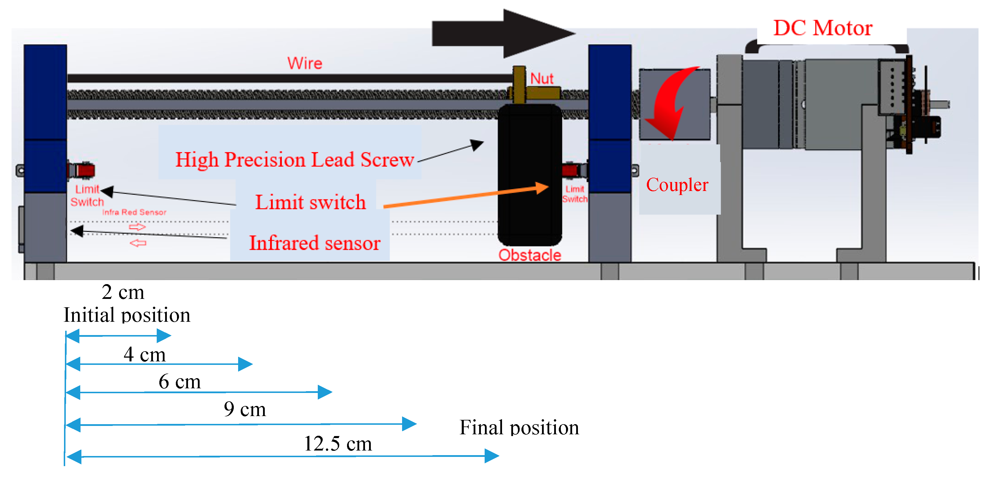
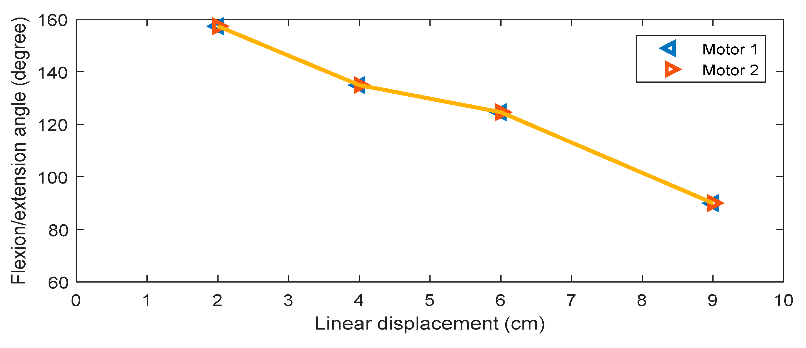
| No | Obstacle Position | Motor-Tendon Actuator and Soft Elbow Position |
|---|---|---|
| 1. | Initial/Normal Position The reading of the IR-Sensor starts from 2 cm which is the starting point (= 0 cm in the starting position). |  |
| 2. | 134.91° Position The IR-Sensor reading is 4 cm in position, moving the arm to an angle of 134.91°. |  |
| 3. | 124.58° Position The IR-Sensor reading is at 6 cm, moving the arm to form an angle of 124.28°. |  |
| 4. | 90° Position The IR-Sensor reading is 9 cm in position, moving the arm in the angle of 90°. |  |
© 2019 by the authors. Licensee MDPI, Basel, Switzerland. This article is an open access article distributed under the terms and conditions of the Creative Commons Attribution (CC BY) license (http://creativecommons.org/licenses/by/4.0/).
Share and Cite
Ismail, R.; Ariyanto, M.; Perkasa, I.A.; Adirianto, R.; Putri, F.T.; Glowacz, A.; Caesarendra, W. Soft Elbow Exoskeleton for Upper Limb Assistance Incorporating Dual Motor-Tendon Actuator. Electronics 2019, 8, 1184. https://doi.org/10.3390/electronics8101184
Ismail R, Ariyanto M, Perkasa IA, Adirianto R, Putri FT, Glowacz A, Caesarendra W. Soft Elbow Exoskeleton for Upper Limb Assistance Incorporating Dual Motor-Tendon Actuator. Electronics. 2019; 8(10):1184. https://doi.org/10.3390/electronics8101184
Chicago/Turabian StyleIsmail, Rifky, Mochammad Ariyanto, Inri A. Perkasa, Rizal Adirianto, Farika T. Putri, Adam Glowacz, and Wahyu Caesarendra. 2019. "Soft Elbow Exoskeleton for Upper Limb Assistance Incorporating Dual Motor-Tendon Actuator" Electronics 8, no. 10: 1184. https://doi.org/10.3390/electronics8101184