Article

Data-Dense and Miniature Chipless Moisture Sensor RFID Tag for Internet of Things

1
Department of Telecommunication Engineering, ACTSENA Research Group, University of Engineering and Technology, Taxila 47050, Pakistan
2
Department of Electrical Engineering, Polytechnique Montreal, Montreal, QC H3T 1J4, Canada
3
Department of Electrical and Computer Engineering, McMaster University, Hamilton, ON L8S 4L8, Canada
4
Department of Electronics Systems, Royal Institute of Technology (KTH), Isafjordsgatan 26, SE 16440 Stockholm, Sweden
5
Department of Information Technology, TUCS, University of Turku, Turku 20520, Finland
*
Authors to whom correspondence should be addressed.
Electronics 2019, 8(10), 1182; https://doi.org/10.3390/electronics8101182
Submission received: 17 September 2019 / Revised: 9 October 2019 / Accepted: 15 October 2019 / Published: 17 October 2019
(This article belongs to the Special Issue Advanced RFID Technology and Applications)

Abstract

:
A novel and miniaturized semi-elliptical 20-bit fully passive chipless RFID sensor tag is proposed in this article. The realized sensor tag is made up of semi-elliptical shaped open-end slots within the compact size of 25 mm × 17 mm. The multi-substrate analysis of the proposed tag is examined using non-flexible and flexible materials. The articulated tag configuration is capable of monitoring moisture levels when the largest resonator is covered by a heat-resistant sheet of Kapton HN (DuPontTM). The proposed tag functions in the operational frequency band of 4.1 GHz–16 GHz and possesses the overall bit density of 4.70 bit/cm2. The structure is composed of a thin passive substrate layer topped with an active layer of conductive path and is considered as a potential candidate for low-cost identification of the tagged objects. In addition to that, its moisture sensing property and flexible nature make it a reliable smart sensor for conformal applications.

1. Introduction

The internet of things (IoT) plays an incredible role in improving the quality of life by connecting millions of smart devices and technologies, and it serves modern-day applications in the fields of industrial automation, smart home, transportation, and healthcare [1]. RFID systems integrated with IoT infrastructure intensify their purpose and functionality for detection as well as sensing [2]. Chipless RFID as a contactless identification technique has gained acceptance due to its prosperous contribution in diverse commercial applications such as asset tracking, automated identification, item-level tagging, access management, and animal tracking on large scales [3]. The building blocks of a chipless RFID system are comprised of a reader, transponder, and data base for extracting and storing information from the remotely located tag [4,5]. In the literature, multiple approaches have been studied for designing chipless RFID tags achieving large information storing capacity and reliable performance. Various resonant structures such as E-shaped, spiral, hairpin type, and C-shaped resonators have been investigated to improve the data encoding capacity of chipless tags [6,7,8,9,10]. Nevertheless, a trade-off exists between compactness and bit density of an RFID tag. Code density is a core factor which determines the compactness of a chipless tag, and it is estimated from certain parameters that are dimensions and number of data bits [11,12]. A tag of C-shaped resonators printed on paper substrate [13] and another tag of Radar Cross-Section (RCS) based C-folded dipole resonators [14] have been designed with an aim to improve the encoding capability of the chipless tag by using different coding techniques. It is observed that reported resonators are incapable of achieving high bit density owing to their large size and reduced data bits for encoding. The dipole resonator-based capacitive loaded chipless RFID tag structure is reported in [15]. Moreover, square loop and cross-loop shaped resonating structures for chipless tag are discussed [16,17,18,19]. The reported structures are primarily designed to enhance bit density of the tag but due to their large size of 17 mm × 68 mm [15], 40 mm × 40 mm [16,17], and low bit capacity of 5-bits [18,19], estimated overall bit density is still low. Therefore, they are not considered suitable for data-dense applications. In [20], a butterfly-shaped frequency selective surface (FSS) based chipless tag with 14 mm × 14 mm footprint is realized on Rogers RT /duroid/5880 substrate. A 9-bit chipless tag structure comprising of circular slots is designed and its performance is investigated for flexible laminate and another inverted M-shaped tag is designed as reported in [21,22]. These recently proposed chipless tags offer optimum bit density but they do not perform sensing. Hence, they can only be used for identification without any additional service.
In addition to the identification and tagging, smart RFID tags provide benefits of ubiquitous sensing of various meteorological data such as humidity and temperature. Chipless RFID sensor tags can be realized using a variety of sensitive materials embedded within tag structure to achieve desired sensing mechanism. For this purpose, diversified state of the art chipless tag designs have been reported in literature, applying some sensitive materials like paper [23,24] and polyvinyl alcohol for monitoring the sensor response of the tag. In [25], a 16-bit extended C-shaped RFID sensor tag is presented, and silicon nanowire is used to achieve sensing. A downside of this work is that the design lacks flexibility as it is fabricated on FR-4 substrate [26]. There is a paper-based chipless tag composed of LC resonators incorporated with humidity sensing. This design is realized using printing technique and paper substrate itself exhibits sensing when exposed to moisture [27]. Furthermore, a 15-bit chipless tag with dimensions of 20 mm × 10 mm is demonstrated and performance is investigated for humidity sensing fulfilling the concept of green electronics [28]. The aforementioned chipless tags use paper substrate to sense moisture levels, which has several disadvantages. There is a strong relationship between sensor parameter and sensor response which is non- linear in case of paper at higher levels of humidity and ultimately it affects the absorption peaks in the RCS curve. Moreover, paper can suffer from innumerable states of structural deformations, and hence, reliability is compromised.
The chipless sensor tags should meet the demands of reliable performance and cost-effectiveness simultaneously. It becomes challenging for the researchers to maintain cost because of complex fabrication techniques which is a matter of contention in case of printable tags. To overcome this problem, flexible substrates using conventional fabrication methods for tag development are incorporated and investigated to achieve optimum performance. Keeping this perspective in mind, a depolarizing nested scatter based chipless humidity sensor tag is examined by placing a thin layer of polyvinyl alcohol in the center of the structure to detect the change in the moisture level of surroundings [29]. A flexible chipless sensor tag using copper resonator is reported in [30]. These reported designs provide flexibility but they are not very compact and suffer from complexity in sensing mechanisms.
In this research work, we present a semi-elliptical shaped novel and flexible passive chipless RFID tag incorporated with moisture sensing capability. The realized tag has potential to store considerable amount of data within the compact dimensions of 25 mm × 17 mm with twenty bits. The proposed design is composed of nested open-ended slots and each slot corresponds to logic state ‘1’ and a resonant frequency, while a shorted slot implies logic state ‘0’. Furthermore, multi-substrate analysis of the proposed chipless tag is presented for two contrasting substrates i.e. Taconic TLX-0 and Rogers RT\duroid\5880 each with its own range of frequency band. The varying electrical properties of the substrates produces profound effects on the performance of the tag. With the choice of flexible substrate, the proposed tag enables new product paradigms that are not possible with conventional substrate material. Besides these advantages, the tag is configured to sense the humidity levels in environment.
The organization of this paper is as follows: Section 2 describes the multistep logical approach towards the design of the proposed sensor tag. This section emphasizes the choice of a semi-elliptical shape that has never been tried before and how it proves to be far superior to conventional circular radiators. Section 3 demonstrates the dual resonant element geometric configuration along with its RCS response. Section 4 discusses the overall geometric configuration of the proposed twenty-bit chipless tag along with its dimensions. Section 5 explains the working mechanism and measurement system of the proposed tag in the standard environment. Section 6 is the vital section comprised of two subsections discussing the results and overall response of the tag for the two substrates. Section 7 highlights the bending effect of the tag. Section 8 presents the design and analysis of moisture sensor integration of the proposed chipless configuration. Section 9 contains the concluding remarks.

2. Logical Approach towards the Proposed Tag Design

The proposed moisture sensor chipless RFID tag is developed by using a systematic procedure. It begins with the concept stage and concludes at the development stage meeting the desired criteria of enhancing the bit density of a cost-effective tag. The presented semi-elliptical shaped chipless sensor tag produces more desirable results as compared to the reported designs in literature [6,7,8,9,10]. The construction of single slotted resonant element begins with the elliptical-shaped structure using moldable Rogers RT/duroid/5880 material, where the overall tag area is determined by two geometric parameters which are labelled as Ma and Mb. Afterwards, the same procedure is applied for remaining elliptical slots using set of mathematical equations given in (1) and (2);
F o r   i = 1 , 2 n
X a i + Y b i = 1
A r e a = π × a i × b i
where i represents the number of the slot, ai is the length of major axis, bi is the length of minor axis of ellipse, and ‘X’ and ‘Y’ represent their intersection points on the plane. As the ellipse is the modified form of a circular radiator therefore, intersection points can be found from (3) and (4) by keeping intersection points of circle with radius ‘r’ as (x0, y0) and for ellipse as (xe, ye) at origin.
( x 0 , y 0 ) = ( x e , y e ) = ( 0 , 0 )
X = ± a r 2 b 2 a 2 b 2
Y = ± a a 2 r 2 a 2 b 2
The anatomy of two equi-central radiators representing the two axis of ellipse and radius of a circle is shown in Figure 1. Our main aim in this work is maximizing bits to size ratio. The tag size is usually inversely related to code density. Code density of the tag means the number of bits encoded per unit area, and it is calculated from Equation (5);
C o d e   D e n s i t y = N u m b e r   o f   b i t s   e n c o d e d L e n g t h t a g × W i d t h t a g
It is evident from the equation above that the size of the tag (considering a rectangular tag as an example of area L e n g t h t a g × W i d t h t a g ) is in direct relation to the number of bits.
In our investigation, elliptical tag offers more bit density (another term for code density) in comparison with the circular tag of same area. Maximizing the bit density of the chipless tag is one of the objectives of the proposed work. Circular resonators are often used in literature to design a tag. From the theoretical analysis of the circular and elliptical structures, it was presumed that the elliptical structure could prove to be superior to the circular structure for realizing an RFID tag. This information is extracted by the analysis of the two shapes, as an elliptical area is controlled by two parameters which leads to enhanced flexibility in design optimization.
For further enhancing the bit density of the chipless tag, the symmetric elliptical shape is cut into two halves at an angle of 30°. In this way, the number of bits increased two times in the same area and finally the asymmetric semi-elliptical shape is obtained as shown in Figure 2.

3. Dual Resonant Element Geometric Design

The proposed fully passive chipless RFID tag containing two slots is shown in Figure 3. There is an asymmetric tag structure with no ground at the back-side. The figure shows geometric dimensions of the conductive path loaded with two slots with total length and width of tag labeled as L = 17 mm and W = 25 mm, respectively. S1 = 0.3 mm and S2 = 0.55 mm represent the horizontal and vertical metallic gaps of the patch from the larger most slots, respectively. Furthermore, P1 = 11.4 mm and P2 = 11 mm are the dimensions of inner metallic portions of radiated element (copper cladding acts as conductive path) from the outer most slots R2 and R1, respectively. The width of slot is C1 = 0.44 mm, and G1 = 1.55 mm symbolizes the distance between the end points of two collocated slots. Initially, the proposed data encoding configuration is evaluated for rigid laminate i.e., Taconic TLX-0 with 0.635 mm thickness. Afterward, the same design is investigated for Roger RT/duroid/5880 substrate holding thickness of 0.508 mm to make it bendable for conformal surfaces. Slots are etched out from the copper cladding of 0.035 mm thickness. The varying dimensions of the slots produce significant effects on the RCS response of the tag and resonant frequency associated with each slot. The resonating frequency of individual slot can be mathematically calculated via Equation (6) [31];
f r = c 2 A 2 r + 1
where ‘c’ represents speed of light, ‘A’ signifies the overall physical area of slot, and ∊r is the permittivity of the substrate used. The proposed tag is excited by incident plane electrometric waves and the RCS response of the tag shown in Figure 3 is given in Figure 4. It is observed that two sharp resonances are produced with no harmonics at lower frequencies of 4.1 GHz and 4.3 GHz.
The current distribution of the above-mentioned tag at the smallest frequency of 4.1 GHz is shown in Figure 5a. It is depicted that the maximum concentration of current is present around the top and bottom side of the slot resonator representing inductive effects, while the minimum density of current is situated around the left and right edges of the slot indicating capacitive effects [32]. Moreover, the 3D radiation pattern of the proposed tag is also observed which shows that the tag radiates in omnidirectional pattern as shown in Figure 5b.

4. Proposed Multi-Resonator Chipless RFID Tag Design

The proposed chipless tag loaded with twenty semi-elliptical nested slots on a single side with no ground has some optimized geometric parameters as shown in Figure 6. The realized tag is comprised of twenty slots labelled from R1 to R20 in a compact size of 25 mm × 17 mm with varying lengths and widths to produce sharp resonances at twenty different frequencies in the RF-spectrum. The proposed tag is designed and investigated for different substrates from non-flexible to flexible i.e., Taconic TLX-0 and Rogers RT/duroid/5880. The slanted separation between all the slots is labeled as G1 = 1.55 mm, while the slot width and gap between neighboring slots are uniform and defined as C1 = 0.44 mm and C2 = 0.35 mm, respectively.
The major axis of the smallest semi-elliptical structure has two labels, i.e., A1 = 4 mm and A2 = 3 mm. The substrate with conductive copper cladding of 35 µm thickness is used for fabrication. The existence of slot specifies the logic state “1”, while absence of slot indicates logic state “0”. The tag optimization is carried out in such a way that using ten elliptical slots gives ten notches. In order to obtain the high bit density in the compact size, we apply the slanted cut at an angle of 30° due to which the number of bits increase to twenty and semi-elliptical shape is obtained. At first, two-slot resonators-based tag is designed to obtain the sharp and clear notches within the desired frequency spectrum. These slots are then replicated towards the center point. The final twenty-bit tag has an operating RF-band of 4.1 GHz- 16 GHz. The slot R1 produces the “most significant bit” (MSB) at the lowest frequency of 4.1 GHz, while the smallest slot R2 produces notch at the largest frequency of 16 GHz named as “least significant bit” (LSB). The design and optimization of the proposed tag are completed using CST Microwave Studio Suite.

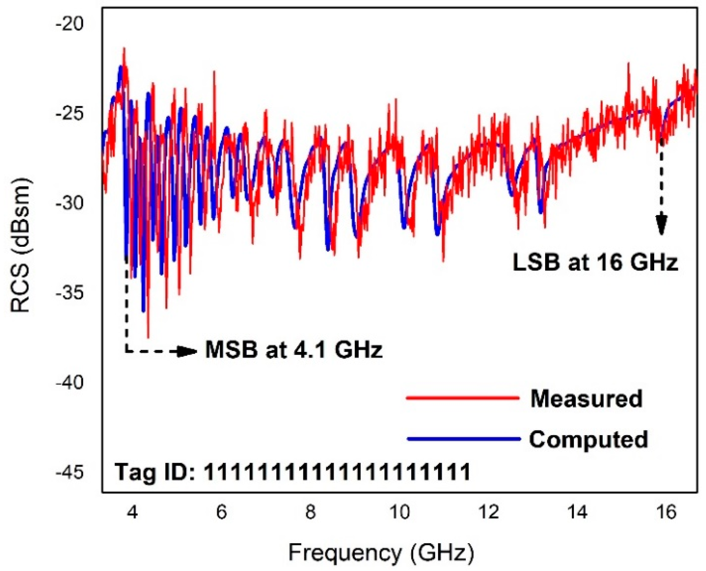
5. Working Principle

The realized chipless RFID tag is a prominent candidate for different IoT based conformal applications. The working mechanism of the formulated chipless tag relies on “backscattering” technique in which the reader or interrogator transmits the electrometric waves towards the tag’s surface. As a consequence of which backscattered encoded signals are received by the reader and information processing takes place with the help of database [33]. The block diagram of the RFID system along with its components is displayed in Figure 7.
The power transmitted by transmitting antenna and received by receiver antenna follows the principle of Friis transmission equation given in (7);
P R P T = ( λ 2 ) ( 4 π r ) 2 G T G R
where ‘PT is transmitted power, ‘PR denotes received power, ‘λ’ represents the wavelength, ’r’ symbolizes the distance between two antennas, and ‘GT and ‘GR are the overall gains of transmitter and receiver antennas, respectively. Incident plane wave is used to energize the RFID tag when placed in the proximity of reader and plane wave propagation takes place in accordance with mathematical expression (8);
E ( x , y , z , t ) = E 0 exp [ j ( w t k z ) ] x ^ + E 0 exp [ j ( w t k z + π 2 ) ] y ^
where E0 denotes electric field, ‘t’ represents time, ‘k’ signifies wave number vector, and (x, y, z) implies the position vector. The fabricated tag in comparison with the area of a euro coin is shown in Figure 8.
The tag is positioned at the far-field distance which can be calculated using Equation (9) to observe the response of the backscattered signal.
R = 2 D 2 λ
Here, ‘D’ is the largest dimension of resonating structure, and ‘R’ illustrates far-field distance. For measuring the RCS response of 20-bit chipless tag in the real environment, a system of measurement consists of transmitting and receiving horn antennas, vector network analyzer (VNA) model R&S ZVL-13 and fabricated model of the tag. The block diagram of the measurement system for the proposed RFID tag is presented in Figure 9.
The read range is another important factor associated with the chipless tag operation. Mathematically, the read range of the tag can be estimated using Equation (10);
R 0 4 = G T G R λ 2 σ P T ( 4 π ) 3 P R
Here, R0 represents read range and ‘σ’ symbolizes the radar cross-section.

6. Results and Discussion

The proposed tag is designed, and its RCS response is investigated for two contrasting substrates that are Taconic TLX-0 and Roger RT/duroid/5880. Table 1 demonstrates the varying electrical properties of these substrates.

6.1. Proposed Tag Response with Taconic TLX-0 Substrate

The presented chipless RFID tag is designed for rigid Taconic TLX-0 substrate with 0.635 mm thickness and permittivity of 2.45. With this substrate, the tag covers the operational RF spectral range of 3.8 GHz–15 GHz as shown in Figure 10. The MSB occurs at 3.8 GHz while LSB appears at 15 GHz with an overall bandwidth of 11.2 GHz.

6.2. Proposed Tag Response with Rogers RT/duroid/5880

The presented RFID tag in this work is designed and investigated for bendable Rogers RT/duroid/5880 laminate holding 0.508 mm thickness and permittivity of 2.2. The RCS reliability graph of the realized data encoding arrangement displaying measured and computed results is illustrated in Figure 11. The RCS response clearly demonstrates twenty sharp responses at different frequencies in the RF spectrum of 4.1 GHz–16 GHz. Making use of Rogers RT/duroid/5880 provides an additional feature of flexibility for the placement on curvilinear surfaces. The measured results depict acceptable settlement with the computed results. It is worth declaring that some tolerable drift is taking place at some frequencies in the RCS curve which is due to nominal fabrication and experimental errors.
The encoding mechanism of the proposed chipless tag is analyzed by evaluating four tags, each with its distinctive ID for storing data. The tag ID is all 0s when all twenty slots are removed, and the corresponding frequencies also disappear (no resonances) in the RCS curve. Then we introduce other sets of slots to obtain following tag IDs: 11001100110011111111, 00111100111111001100, 00001111001111111100. The RCS response with different bit sequences of the proposed tag is shown in Figure 12. It is observed that there is a nominal shift in the resonant frequencies due to removal of slots (also referred to as shorted resonators) from the tag design. This tolerable shifting happens because of the existence of mutual coupling between the adjacent slots that can be overcome through simple signal processing techniques [34].

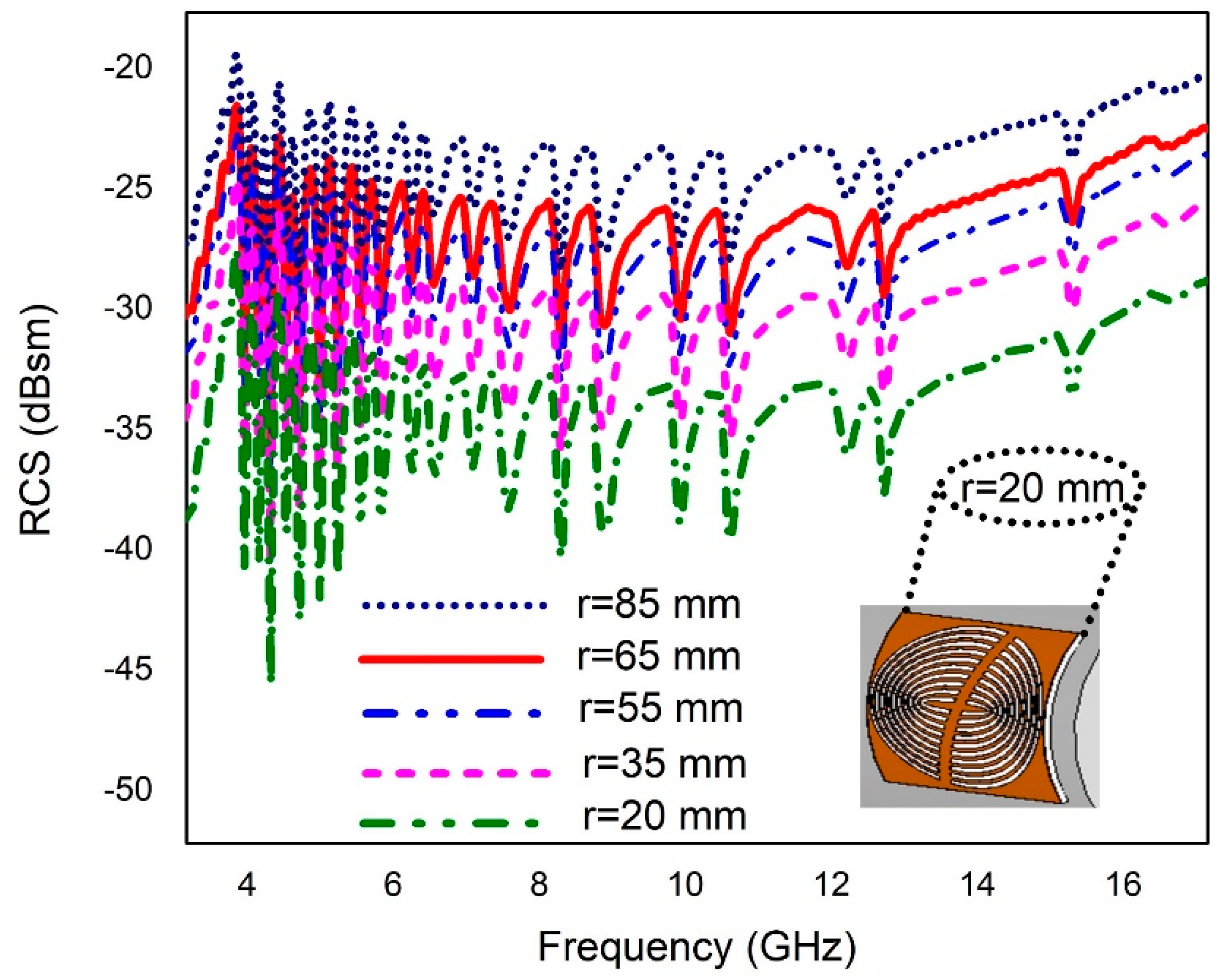
7. Bending Effect of the Proposed Chipless Tag

The deformation analysis of the chipless tag under consideration is investigated and its performance is experimentally analyzed by bending it at several curvature radii i.e., 85 mm, 65 mm, 55 mm, 35 mm, and 20 mm. The bending effect is introduced by placing the tag in curved position using molds that are constructed with polystyrene material. The choice of the supporting material depends on its permittivity value which is close to unity for polystyrene [35]. The RCS response of the framed tag with bending effect at different radii symbolized by “r” is shown in Figure 13. It is evident from the graph that the changing curvature of the tag does not readily affect the overall performance, and resonant dips are still detectable. The RCS response is shifted downward with a decrease in the bending radius of the tag [36]. Nevertheless, the noteworthy outcome of this evaluation is that the information stored in the bent version of the tag is effectively recovered without any losses, therefore, it can be reliably deployed on conformal surfaces due to its flexible nature.

8. Proposed Tag as Moisture Sensor

The proposed compact chipless RFID tag holds an additional aspect of moisture sensing. The moisture sensor integration is brought by depositing the polyimide sheet of Kapton HN on the larger most slot/resonator in the design. The two-dimensional cross-sectional image showing different layers of a part of the proposed moisture sensor tag is given in Figure 14.
The fundamental operating principle of the moisture sensor chipless tag is dependent upon the electrical properties of Kapton HN of 0.125 mm thickness and a close relation of its permittivity variation with the relative humidity of the environment. In the same flexible tag design of Rogers RT\duroid\5880 substrate, a thin layer of Kapton HN is coated on two consecutive slots\resonators considered as sensing resonators as shown in Figure 15. Kapton polyimide film is selected for sensing purpose as their chemical structure anatomy shows that they are made through heat-activated poly-condensation. Hydrolysis effect takes place when polyimide sheet absorbs moisture from the air which causes breakdown of polyimides internal carbon-nitrogen bonds. This bond breakage alters the internal electrical polarization which leads to the variation of permittivity of polyimide at different levels of moisture [37]. According to the datasheet of Kapton HN [38] film, the variation in its relative permittivity (∊r = 3.05–3.9) will change in accordance with the percentage humidity of the environment from 0% RH to 100% RH. Hence, the resonance frequencies associated with sensing resonators shift towards the left side of the RCS curve, while all the remaining resonators maintain their previous frequency response as per the tag ID. The change in relative permittivity of Kapton is related to the relative humidity [39] as given in Equation (11);
% R H = r   3.05 0.008
To validate the moisture sensor behavior, the tag is investigated experimentally in the climatic chamber by Weiss Technik WK 11-180 to monitor response at various humidity levels. It is observed that for every step increment in %RH from 15% to 100%, the resonance frequencies of the two sensing resonators drift towards the left side in the RCS graph as shown in Figure 16. Table 2 demonstrates the comparison of different chipless RFID tags with the proposed sensor tag. It is evident that the proposed configuration holds the promising properties and improved results as compared to the listed tag designs.

9. Conclusions

This paper presents a compact, cost-effective, and bendable chipless RFID sensor tag integrated with dual functionality of moisture sensing as well as item-level tagging of millions of objects simultaneously. The proposed multi-resonator based tag is investigated for multiple substrates holding distinct electrical properties, i.e., Taconic TLX-0 and Rogers RT\duroid\5880. The tag yields twenty bits and is capable to bring forth 2 20 = 1 , 048 , 576 individual tag IDs. Furthermore, moisture sensing is accomplished by placing a thin sheet of Kapton HN within the slotted RFID tag structure to monitor real-time humidity level variations of the application or environment and results show that sensing mechanism does not impact the tagging operation. Thus, the articulated semi-elliptical sensor tag is considered a notable candidate for cost-effective conformal applications.

Author Contributions

Conceptualization I.J.; Data curation, I.J.; Formal analysis, A.E.; Investigation, M.U.R., M.J.K. and Y.A.; Methodology, I.J. and M.U.R.; Project administration, Y.A.; Resources, M.N. and H.T.; Software, M.J.K; Supervision, A.E. and Y.A.; Validation, H.T. and M.N.; Visualization, M.J.K. and A.E.; Writing—original draft, I.J.; Writing—review & editing, M.U.R.

Funding

This research is funded by the Higher Education Commission of Pakistan Technology development fund (HEC-TDF-67/2017).

Acknowledgments

We thank Higher Education Commission of Pakistan for Technology Development Fund (HEC-TDF-67/ 2017), University of Engineering and Technology, Taxila for financial assistance of this work via ACTSENA research group funding and Vinnova (The Swedish Government Agency for Innovation Systems).

Conflicts of Interest

The author declares no conflict of interest in this publication.

References

  1. Bolic, M.; Rostamian, M.; Djuric, P.M. Proximity detection with RFID: A step toward the internet of things. IEEE Pervasive Comput. 2015, 14, 70–76. [Google Scholar] [CrossRef]
  2. Al-Fuqaha, A.; Guizani, M.; Mohammadi, M.; Aledhari, M.; Ayyash, M. Internet of things: A survey on enabling technologies, protocols, and applications. IEEE Commun. Surv. Tutor. 2015, 17, 2347–2376. [Google Scholar] [CrossRef]
  3. Rezaiesarlak, R.; Manteghi, M. Design of chipless RFID tag based on characteristic mode theory (CMT). IEEE Trans. Antennas. Propag. 2015, 63, 711–718. [Google Scholar] [CrossRef]
  4. Islam, M.A.; Karmakar, N.C. Compact printable chipless RFID systems. IEEE Trans. Microw. Theory Tech. 2015, 63, 3785–3793. [Google Scholar] [CrossRef]
  5. Ma, Z.; Jiang, Y. High density 3D printable chipless RFID tag with structure of passive slot rings. Sensors 2019, 19, 2535. [Google Scholar] [CrossRef] [PubMed]
  6. Sumi, M.; Dinesh, R.; Nijas, C.M.; Mridula, S.; Mohanan, P. High bit encoding chipless RFID tag using multiple E shaped microstrip resonators. Prog. Electromagn. Res. B 2014, 61, 185–196. [Google Scholar] [CrossRef]
  7. Gu, Q.; Wan, G.C.; Gao, C.; Tong, M.S. Frequency-coded chipless RFID tags based on spiral resonators. In Proceedings of the 2016 Progress in Electromagnetics Research Symposium (PIERS), Shanghai, China, 8–11 August 2016; pp. 844–846. [Google Scholar]
  8. Martinez, M.; Weide, D. Compact single-layer depolarizing chipless RFID tag. Microw. Opt. Tech. Lett. 2016, 58, 1897–1900. [Google Scholar] [CrossRef]
  9. Mumtaz, M.; Amber, S.F.; Ejaz, A.; Habib, A.; Jafri, S.I.; Amin, Y. Design and analysis of C-shaped chipless RFID tag. In Proceedings of the 2017 International Symposium on Wireless Systems and Networks (ISWSN), Lahore, Pakistan, 19–22 November 2017; pp. 1–5. [Google Scholar]
  10. Sakouhi, S.; Raggad, H.; Garsallah, A.; Latrach, M. A novel H-shaped cavity based RFID chipless tag. In Proceedings of the Second International Conference on Advanced Technologies for Signal and Image Processing (ATSIP), Monastir, Tunisia, 21–23 March 2016; pp. 820–823. [Google Scholar]
  11. Khan, M.M.; Tahir, F.A.; Farooqui, M.F.; Shamim, A.H.M. Cheema.3.56 bits/cm2 compact inkjet printed and application specific chipless RFID tag. IEEE Antennas Wirel. Propag. Lett. 2016, 15, 1109–1112. [Google Scholar] [CrossRef]
  12. Adbulkawi, W.M.; Sheta, A.F.A. Printable chipless RFID tags for IOT applications. In Proceedings of the IEEE International Conference on Computer Application and Info Security. (ICCAIS), Riydah, Saudi Arabia, 4–6 April 2018; pp. 1–4. [Google Scholar]
  13. Vena, A.; Perret, E.; Tedjini, S.; Tourtollet, P.E.G.; Delattre, A.; Garet, F.; Boutant, Y. Design of chipless RFID tags printed on paper by flexography. IEEE Trans. Antennas Propag. 2013, 61, 5868–5877. [Google Scholar] [CrossRef]
  14. Rance, O.; Siragusa, R.; Auger, L.P.; Perret, E. Towards RCS magnitude level coding chipless RFID. IEEE Trans. Microwave Theory Tech. 2016, 64, 2315–2325. [Google Scholar] [CrossRef]
  15. Havlicek, J.; Svanda, M.; Polivka, M.; Machac, M.; Kracek, J. Chipless RFID tag based on electrically small spiral capacitively loaded dipole. IEEE Antennas Wirel. Propag. Lett. 2017, 16, 3051–3054. [Google Scholar] [CrossRef]
  16. Chen, N.; Shen, Y.; Dong, G.; Hu, S. Compact scalable modeling of chipless RFID tag based on high-impedance surface. IEEE Trans. Electron. Device 2019, 66, 200–206. [Google Scholar] [CrossRef]
  17. Emran, F.; Hanafi, E.; Lim, E.H.; Mahyiddin, M.W.A.W.; Harun, W.S.; Umair, H.; Soboh, R.; Makmud, H.M. Miniature compact folded dipole for metal mountable UHF RFID tag antenna. Electronics 2019, 8, 713. [Google Scholar]
  18. Sajitha, R.V.; Nijas, M.C.; Roshna, K.T.; Vasudevan, K.; Mohanan, P. Compact cross loop resonator based chipless RIFD tag with polarization insensitivity. Microwave Opt. Technol. Lett. 2016, 58, 944–947. [Google Scholar] [CrossRef]
  19. Dong, G.; Shen, Y.; Meng, H.; Chen, N.; Dou, W.; Hu, S. Printable chipless RFID tag and dual-cp reader for internet of things. ACES J. 2018, 33, 494–498. [Google Scholar]
  20. Riaz, M.A.; Yassin, A.; Shahid, H.; Amin, Y.; Akram, A.; Tenhunen, H. Novel butterfly slot based chipless RFID tag. Radioengineering 2018, 27, 776–783. [Google Scholar] [CrossRef]
  21. Habib, A.; Azam, M.A.; Amin, Y.; Tenhunen, H. Chipless slot resonators for IoT system identification. In Proceedings of the IEEE International Conference on Electro Information Technology, Grand Forks, ND, USA, 19–21 May 2016; pp. 0341–0344. [Google Scholar]
  22. Abdulkawi, W.M.; Sheta, A.F.A.; Issa, K.; Alshebeili, S.A. Compact printable inverted-M shaped chipless RFID tag using dual polarization excitation. Electronics 2019, 8, 580. [Google Scholar] [CrossRef]
  23. Kim, S.; Georgiadis, A.; Tentzeris, M.M. Design of inkjet-printed RFID based sensor on paper: Single and dual-tag sensor topologies. Sensors 2018, 18, 1958. [Google Scholar] [CrossRef]
  24. Islam, T.M.; Alam, T.; Yahya, I.; Cho, M. Flexible radio frequency identification (RFID) tag antenna for sensor applications. Sensors 2018, 18, 4212. [Google Scholar] [CrossRef]
  25. Genovesi, S.; Costa, F.; Borgese, M.; Dicandia, F.A.; Manara, G.; Tedjini, S.; Perret, E. Enhanced chipless RFID tags for sensors design, 2016. In Proceedings of the IEEE International Symposium on Antennas and Propagation (APSURSI), Fajardo, Puerto Rico, 26 June–1 July 2016; pp. 1275–1276. [Google Scholar]
  26. Salmeron, J.; Albrecht, A.; Kaffah, S.; Becherer, M.; Lugli, P.; Rivadeneyra, A. Wireless chipless systems for humidity sensing. Sensors 2018, 18, 2275. [Google Scholar] [CrossRef]
  27. Feng, Y.; Xie, L.; Chen, Q.; Zheng, R.L. Low-cost printed chipless RFID humidity sensor tag for intelligent packing. IEEE Sens. J. 2015, 15, 3201–3208. [Google Scholar] [CrossRef]
  28. Zeb, S.; Habib, A.; Amin, Y.; Tenhunen, H.; Loo, J. Green electronic based chipless humidity sensor for IoT applications. In Proceedings of the 2018 IEEE Green Electronics Conference (Green Tech), Austin, TX, USA, 4–6 April 2018; pp. 172–175. [Google Scholar]
  29. Fan, S.B.; Chang, T.H.; Liu, X.Y.; Fan, Y.; Tentzeris, M.M. A depolarizing chipless RFID tag with humidity sensing capability. In Proceedings of the 2018 IEEE International Symposium on Antennas and Propagation & USNC/URSI National Radio Science Meeting, Boston, MA, USA, 8–13 July 2018; pp. 2469–2470. [Google Scholar]
  30. Sajal, S.; Atanasov, Y.; Braatten, D.B.; Marinov, V.; Swenson, O. Low cost flexible passive UHF RIFD tag for sensing moisture based on antenna polarization. In Proceedings of the IEEE International Conference on Eletro/Information Technology, Milwaukee, WI, USA, 5–7 June 2014; pp. 542–545. [Google Scholar]
  31. Dissanayake, T.; Esselle, K.P. Prediction of the notch frequency of slot loaded printed UWB antennas. IEEE Antennas Propag. Soc. 2007, 55, 3320–3325. [Google Scholar] [CrossRef]
  32. Tariq, N.; Riaz, M.A.; Shahid, H.; Khan, J.M.; Khan, S.M.; Amin, Y.; Loo, K.K.; Tenhunen, H. Orientation Independent Chipless RFID Using Novel Trefoil Resonators. IEEE Access 2019, 7, 122398–122407. [Google Scholar] [CrossRef]
  33. Barman, B.; Bhaskar, S.; Singh, A.S. Spiral resonator loaded S-shaped folded dipole dual band UHF RFID tag antenna. Microw. Opt. Tech. Lett. 2018, 61, 720–726. [Google Scholar] [CrossRef]
  34. Islam, A.M.; Yap, Y.; Karmakar, N. ‘▲’ Slotted compact printable orientation insensitive chipless RFID tag for long range applications. In Proceedings of the 2016 9th International Conference on Electrical and Computer Engineering (ICECE), Dhaka, Bangladesh, 20–22 December 2016; pp. 283–286. [Google Scholar]
  35. Betancourt, D.; Haase, K.; Hubler, A.; Ellinger, F. Bending and folding effect study of flexible fully printed and late- stage codified octagonal chipless RFID tags. IEEE Trans. Antennas Propag. 2016, 64, 2815–2823. [Google Scholar] [CrossRef]
  36. Dey, S.; Saha, N.; Alomainy, A. Design and performance analysis of narrow band textile antenna for three different substrate permittivity materials and bending consequences. In Proceedings of the 2011 Lough borough Antennas and Propagation Conference, Lough Borough, UK, 14–15 November 2011; pp. 1–5. [Google Scholar]
  37. Virtanen, J.; Ukkonen, L.; Bjorninen, T.; Elsherbeni, Z.A.; Sydanheimo, L. Inkjet-printed humidity sensor for passive UHF RFID systems. IEEE Trans. Instrum. Meas. 2011, 60, 2768–2777. [Google Scholar] [CrossRef]
  38. Kapton®HN Polyimide Film Datasheet. Available online: http://www2.dupont.com/Kapton/en_US/ (accessed on 18 September 2011).
  39. Ali, A.; Jafri, S.I.; Habib, A.; Amin, Y.; Tenhunen, H. RFID humidity sensor tag for low-cost applications. ACES J. 2017, 32, 1080–1088. [Google Scholar]
  40. Islam, A.M.; Karmakar, N.C. A compact printable dual polarized chipless RFID tag using slot length variation in ‘I’ slot resonators. In Proceedings of the 2015 European Microwave Conference (EuMC), Paris, France, 7–10 September 2015; pp. 96–99. [Google Scholar]
  41. Habib, A.; Asif, R.; Fawwad, M.; Amin, Y.; Loo, J.; Tenhunen, H. Directly printable compact chipless RFID tag for humidity sensing. IEICE Electron. Express 2017, 14, 20170169. [Google Scholar] [CrossRef]
  42. Dey, S.; Karmakar, N.C. An IoT empowered flexible chipless RFID tag for low cost item identification. In Proceedings of the 2017 IEEE Region 10 Humanitarian Technology Conference (R10-HTC), Dhaka, Bangladesh, 21–23 December 2017; pp. 179–182. [Google Scholar]
Figure 1. Anatomy of two equi-central radiators.
Electronics 08 01182 g001
Figure 2. Geometrical configuration of symmetric elliptical and asymmetric semi-elliptical resonator.
Electronics 08 01182 g002
Figure 3. Dual resonant element geometric design.
Electronics 08 01182 g003
Figure 4. RCS response of dual resonant elements.
Electronics 08 01182 g004
Figure 5. (a) Current density at 4.1 GHz. (b) 3-D radiation pattern of dual resonators.
Electronics 08 01182 g005
Figure 6. Proposed multi-resonator chipless tag layout.
Electronics 08 01182 g006
Figure 7. RFID system components.
Electronics 08 01182 g007
Figure 8. Proposed tag fabricated model.
Electronics 08 01182 g008
Figure 9. Block diagram of measurement system.
Electronics 08 01182 g009
Figure 10. RCS response with Taconic TLX-0.
Electronics 08 01182 g010
Figure 11. Computed and Measured RCS response.
Electronics 08 01182 g011
Figure 12. Various bit encoding sequences.
Electronics 08 01182 g012
Figure 13. Bending analysis of the proposed tag.
Electronics 08 01182 g013
Figure 14. Cutting plane view of a portion of the proposed moisture sensor tag.
Electronics 08 01182 g014
Figure 15. Proposed moisture sensor tag layout.
Electronics 08 01182 g015
Figure 16. RCS response of the tag for moisture sensing.
Electronics 08 01182 g016
Table 1. Comparison analysis with two laminates.
SpecificationsPrototype ‘A’Prototype ‘B’
Substrate usedTaconic TLX-0Rogers RT/duroid/5880
Thickness (mm)0.6350.508
Loss tangent0.00190.0009
Permittivity2.452.2
Flexibility🗴
Frequency Band (GHz)3.8–154.1–16
Table 2. Comparison of different RFID tags with the proposed work.
Resonator ShapeTag Size (cm2)No. of BitsFlexibilitySensingBit Density (bits/cm2)
E-Shaped [6]17.708🗴🗴0.45
C-Shaped [9]810🗴🗴1.25
Rectangle [12]3.406🗴🗴1.771
I-Shaped [40]4.4116🗴🗴4.1
L-Shaped [41]7.14081.12
Spiral [42]33.610🗴0.3
Proposed Work4.25204.70

