Article

Parallel Control of Converters with Energy Storage Equipment in a Microgrid

School of Electrical and Electronic Engineering, North China Electric Power University, Beijing 102206, China
*
Author to whom correspondence should be addressed.
Electronics 2019, 8(10), 1110; https://doi.org/10.3390/electronics8101110
Submission received: 29 July 2019 / Revised: 18 September 2019 / Accepted: 26 September 2019 / Published: 2 October 2019
(This article belongs to the Special Issue Advanced Power Conversion Technologies)

Abstract

:
The converter in a microgrid uses the active power and reactive power (PQ) control strategy when connected to the grid. In the case of failure of large power grid, the converters are required to be connected in parallel under the condition of island to provide power to the load. In this paper, a new control method for the parallel operation of converters based on V/F control is proposed. The V/F control is used to ensure the output voltages have the same amplitude and frequency, then the converters will only produce circulating current caused by phase angle inconsistency. The phase angle self-synchronization strategy is proposed to make sure the phase angle of output voltage of all converters in the system are consistent. First, a large inductor is added to the end of the converter to ignore the line reactance, through this, the measured voltage at the terminal of the converter roughly equals to the voltage of the load, thus, every converter has the same reference of phase angle. Using the proposed phase angle self-synchronization strategy allows the output voltage of every converter to have the same phase angle, so that there is no circulating current between converters, and the power is evenly distributed among the converters. The simulation verification was carried out on the Power Simulation (PSIM) simulation platform, and the experimental verification was implemented on the hardware experimental platform. Both results demonstrate the effectiveness of the proposed strategy. This method is highly reliable and easy to implement, and the circulating current can be reduced effectively.

1. Introduction

Energy has always been the basic resource for human survival. Due to the energy crisis and the environmental security, governments all over the world have begun to attach great importance to renewable energy generation [1]. Renewable energy generation plays an irreplaceable role in energy conservation and emission reduction. The distributed generation has developed rapidly in recent years. It is not only an important energy supplement of the main grid, but also an effective way to realize a multiple energy supply, as well as an embodiment of efficient utilization of multiple energy.
With the development of distributed generation, higher requirements were put forward for converter capacity, operational performance, and expansibility. The parallel operation of converters can share the load power among converters, making the device bear less current stress and improving reliability of the system. In addition, after reducing the capacity of a single converter, the size and weight of the converter module will be reduced, making it easier to realize modularization, thus the costs of production and maintenance of the converter is reduced. Therefore, the parallel operation of converters is not only the basis of realizing the reliability, redundancy, and high capacity of distributed generation systems, but also has a great significance for the realization of high-power systems, as well as the improvement of its stability and economy [2].
The safe and stable operation of the parallel converter system needs to meet the following conditions [3]:
(1)
When a single or multiple converter unit exits the parallel system, the remaining converter units can operate normally and meet corresponding power requirements.
(2)
When a single or multiple converter unit are connected to the parallel system, each converter unit can operate stably, which has no influence on the voltage of the system, especially the sensitive load.
(3)
In the parallel system, each converter unit can equally distribute the active and reactive power of the system, so that the circulating current of the system is small.
(4)
In the parallel system, when one converter unit fails, the system can quickly identify it and cut it off in time without affecting the normal operation of other converter units.
References [4,5] studied the parallel strategy of centralized control. In this method, the centralized controller needs to collect the output current of the system, and the current reference of the single converter is obtained after calculation, and the centralized controller will generate the voltage reference of each converter. In [6], a virtual impedance comprehensive control (VICC) strategy was proposed, and the strategy can weaken the harmonic amplification effectively, and improved the filtering performance significantly. The above centralized control method is relatively simple, but it is complicated with poor reliability, which greatly limits its application in the converter parallel system. In [7,8], a distributed networked control system was used in order to implement a distributed secondary control (DSC). In [9] the authors proposed a novel distributed control for uninterruptible power supply (UPS) modules in parallel operation. In the above distributed control method, the current sharing bus transmits the average current signal, and the synchronous bus transmits the synchronous frequency and phase signals of the system. While receiving the information, each converter must transmit its own working information to the current sharing bus and synchronize bus. Distributed control parallel systems require many signal lines, and the reliability of the system is low. At the same time, there are generally multiple converters in the parallel system, which requires more signal lines and is difficult to apply to long-distance transmission systems. In [10], a new communication strategy for decentralized control of paralleled multi-inverter systems was introduced, and the strategy had a good performance in removing frequency. In [11,12] the authors studied the parallel strategy of master-slave control. In the method, the main converter needs to maintain the voltage stability of the parallel system, and its current serves as the current reference of each slave converter. The master-slave control is simpler to implement, but once the main converter fails, the system voltage is not supported, and the current reference signal from each converter is lost, which will cause the parallel system to collapse. In [13,14,15] the authors studied the parallel strategy of Circular Chain Control. The converter in the system forms a ring, and the output current of each converter above is the current reference. The advantage of the 3C control method is that the number of signal lines is relatively reduced, but once one converter in the system fails, the entire parallel system collapses. In [16,17], converter parallel operation used power lines for communication. In [18] the authors proposed a novel wireless parallel control for inverters based on power line communication (PLC). The power line communication control method utilizes the power line for information transmission, and the system information is superimposed on the output voltage of the converter through the high frequency carrier for transmission, so the carrier communication may affect the quality of the output voltage of the converter, causing a voltage quality problem. It has high requirements for filtering and high cost, so it is not suitable for large-scale promotion. In [19,20] the authors proposed a smooth transition control strategy for voltage-source inverters between stand-alone (SA) and grid-connected (GC) modes of operation. In [21], an improved virtual power-based control method for the droop-controlled parallel inverters with a unified rotation angle in the power transformation was proposed. Additionally, in [22,23,24], to achieve the proper power balance and minimize the circulating current in the different impedance situations, a novel droop controller that considers the impact of complex impedance was proposed. In the parallel system with droop control strategy, there is no interconnecting line between the converters. The converter detects its own output active power and reactive power and adjusts the output frequency and voltage amplitude according to the droop coefficient, to realize current sharing. The parallel system of the converter controlled by the drooping eliminates the interconnection line completely, the redundancy and parallel connection of distributed generation system is realized. However, when the main-grid voltage is disturbed, it is easy to cause the system to lose stability. In addition, the droop control strategy takes a long time to adjust, the algorithm is complex, and the dynamic performance is poor.
In the grid-connected control of converters, most converters use PQ control mode. In the case of large power grid failure, the microgrid is switched to island mode, and the converter needs to change the parallel control scheme. Therefore, based on the existing study of parallel operation strategy of converters, a new control method for the parallel operation of converters based on V/F control is proposed. Firstly, the V/F control is used to ensure the output voltages with the same amplitude and frequency, then the reason for the circulating current of the converter is that the phase angles of the output voltage of the converter is not consistent. Then the phase angle self-synchronization strategy is proposed to make the phase angle of all output voltages consistent. Finally, the phase angle, amplitude and frequency of the output voltage in the parallel system are consistent. There is no circulating current between the converters, and the load power is distributed evenly.
Compared with the parallel strategy using communication lines, the existence of communication lines affects the stability and reliability of the system, while the power line transmission data requires the use of demodulation chips, which is less economical. As for droop control, its advantage lies in that it can achieve power distribution within a certain range. However, once the main network voltage is disturbed, droop control will easily lead to instability of the system. In addition, droop control has a long adjustment time, complex algorithm and poor dynamic performance. The parallel control strategy of the converter proposed in this paper does not require the use of communication lines, and the operation is stable and reliable, the implementation principle is simple, and the hardware is easy to implement. Finally, the circulation of the system is small, and the load power is evenly distributed.

2. Converter Modeling and Circulating Current Analysis

2.1. Converter Main Circuit

In the microgrid system, under the grid-connected operation mode, the voltage of the microgrid system is controlled by the large power grid. The converters in the system use the PQ control mode, and each converter can inject power to the load. After the failure of the large power grid, the microgrid enters the island mode, and the parallel control mode of the converter changes accordingly. The topology of a single converter using the V/F control mode is shown in Figure 1.
The three-phase voltage source converter uses a three-phase full-bridge topology, and its detailed structure is shown in Figure 1. The three bridge arms of the converter are connected to the LC filter, and the three-phase output voltage is the terminal voltage on the filter capacitor.
Neglecting the higher harmonics, the three-phase current on filter inductor and the three-phase voltage on filter capacitor are selected as state variables, the state equations of filter inductance and filter capacitance are deduced respectively. According to Kirchhoff’s law of voltage and current, the following formula can be obtained as shown in Equations (1) and (2):
L f d d t [ i L a i L b i L c ] = [ u i a u o a u i b u o b u i c u o c ] ,
C f d d t [ u o a u o b u o c ] = [ i L a i o a i L b i o b i L c i o c ] ,
where udc is the input voltage of the DC side, C is the voltage stabilizing capacitor on the DC side, idc is the current of the DC side, uia, uib, uic are respectively the three-phase unfiltered voltage output by the converter, Lf is the filter inductance, Cf is the filter capacitance, iLa, iLb, iLc are respectively the three-phase current on filter inductance, iCa, iCb, iCc are respectively the three-phase current on filter capacitance, ioa, iob, ioc are respectively the three-phase current output by the converter, uoa, uob, uoc are respectively the three-phase voltage output by the converter, as well as the three-phase voltage on capacitance. Through Equations (1) and (2), the state equation of the converter system can be obtained as shown in Equation (3):
d d t [ i L a i L b i L c u o a u o b u o c ] = [ 0 0 0 1 L f 0 0 0 0 0 0 1 L f 0 0 0 0 0 0 1 L f 1 C f 0 0 0 0 0 0 1 C f 0 0 0 0 0 0 1 C f 0 0 0 ] [ i L a i L b i L c u o a u o b u o c ] + [ 0 0 0 1 L f 0 0 0 0 0 0 1 L f 0 0 0 0 0 0 1 L f 1 C f 0 0 0 0 0 0 1 C f 0 0 0 0 0 0 1 C f 0 0 0 ] [ i o a i o b i o c u i a u i b u i c ] .
According to the above state equation of the converter, that only two of the three AC components are independent of each other in the three-phase bridge converter model, then the Clark transformation and Park transformation are introduced to realizing non-differential proportion integration (PI) adjustment. Then the voltage and current dual loops are obtained, as shown in Figure 2 and Figure 3, where in KPWM represents the amplification factor of the converter, the current inner loop can be regarded as Gi(s) in the voltage outer loop.

2.2. Circulating Current Analysis

Taking parallel operation of two converters as an example, the circulating current is analyzed in Figure 4.
Generally, the load is inductive impedance or resistive impedance. When the impedance properties are different, the circulating current changes accordingly.
(1) System output impedance is inductive:
In Figure 5, under the condition that the output impedance is inductive, when the amplitudes of the output voltages of the two converters in the system are the same and the phase angles are different, the active circulating current flows from the phase leading converter to the phase lagging converter. When the output voltage phase angles are consistent and the amplitudes are different, the reactive circulating current flows from the high amplitude converter to the low amplitude converter. When the amplitude and phase of output voltage are all different, the active and reactive components of the circulating current exist simultaneously.
(2) System output impedance is resistance:
In Figure 6, under the condition that the output impedance is resistance, when the amplitudes of the output voltages of the two converters in the system are the same and the phase angles are different, the reactive circulating current flows from the phase lagging converter to the phase leading converter. When the phase angles of output voltage are consistent and its amplitudes are different, the active circulating current flows from the high amplitude converter to the low amplitude converter. When the amplitude and phase of output voltage are different, the active and reactive components in the circulating current exist simultaneously.
When the system output impedance contains both the inductive component and resistance component, both the amplitude difference and phase of output voltage difference of the parallel converter unit will cause the system active and reactive circulating current simultaneously, so the effect of voltage amplitude difference and phase difference on system circulating current are coupled, so it is difficult to determine the direction of the circulating current by the amplitude and phase of output voltage. It can be seen from above that the first problem to be solved in parallel operation of converter is the circulating current between the converters, after that the output load power can be distributed according to the capacity of the converter.

2.3. Parallel Requirement

The converter outputs a sine wave that varies at any time. In order to realize parallel operation of the converter, the amplitude, frequency, and phase of the output voltage of each converter unit must be strictly consistent. Once there are differences in one of them, it will inevitably lead to the existence of circulating current between the converters. This will not only make the power distribution of the system uneven, but also cause the current stress of devices to be too high, which may make the whole system fail.
In the process of hardware implementation, due to device differences, clock effects and phase-locked differences and other reasons, a voltage deviation inevitably formed between converters, which causes circulating current. When the converter is parallel, the output voltage between the converter units must be strictly controlled to make the amplitude, frequency and phase of the output voltage consistent, then the converter unit can share the load power reasonably.
Based on the above research, this paper proposed a new control method for the parallel operation of converters based on V/F control. The V/F control is used to ensure the amplitude and frequency of the output voltage consistent then the converter will produce circulating current due to inconsistent phase angle. Then the phase angle self-synchronization strategy was proposed to make the phase angle of the output voltage consistent, so that the system is free of circulating current, and achieves the purpose of power sharing.

3. Parallel Strategy of Converter

3.1. Proposal of Parallel Strategy

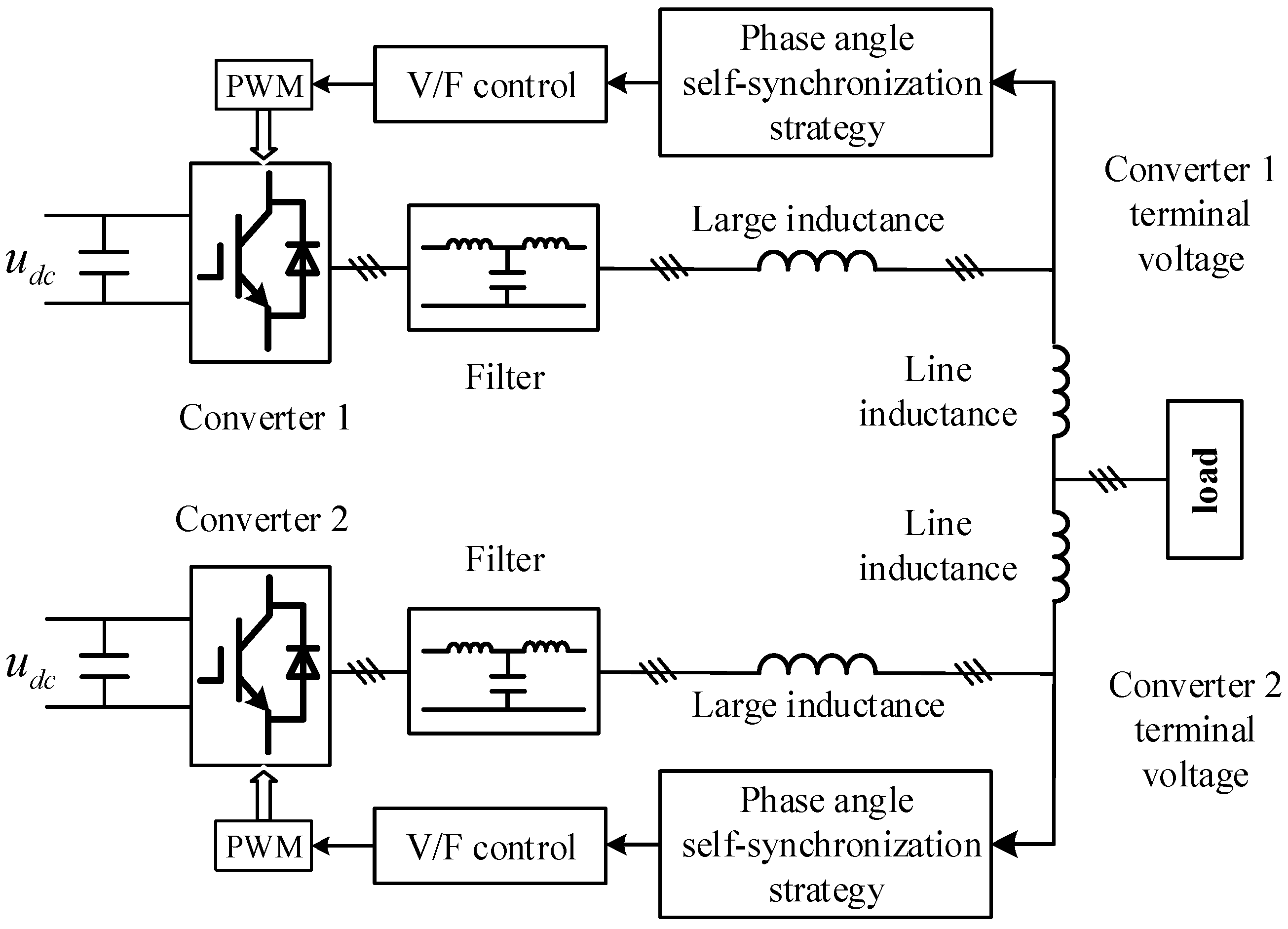
After the failure of large power grid, the converter in the microgrid needs to change from PQ operation mode to another control mode. In this paper, the converter parallel control strategy is proposed. Firstly, the converter unit adopts the constant voltage and constant frequency (V/F) control, as shown in 
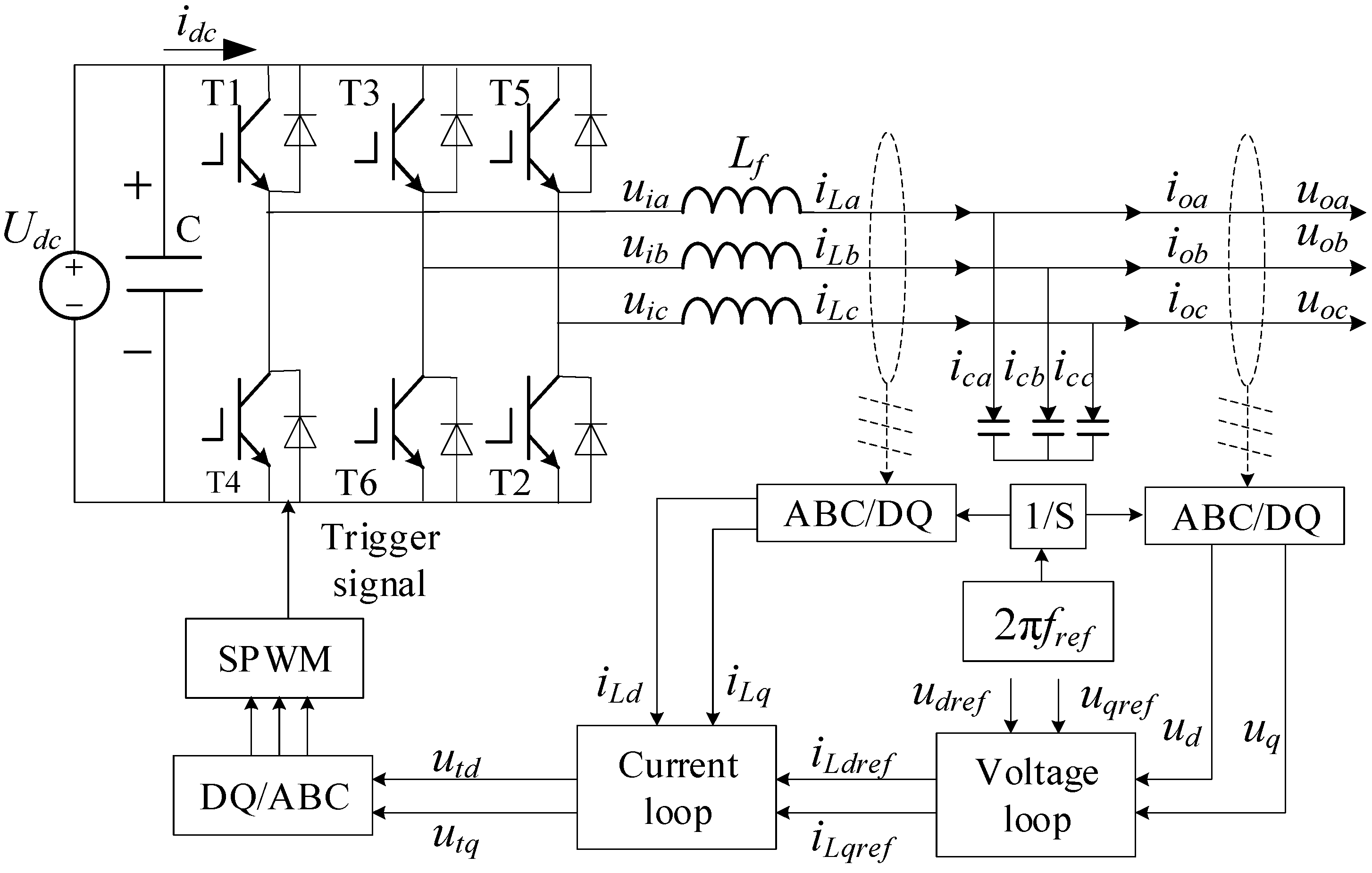
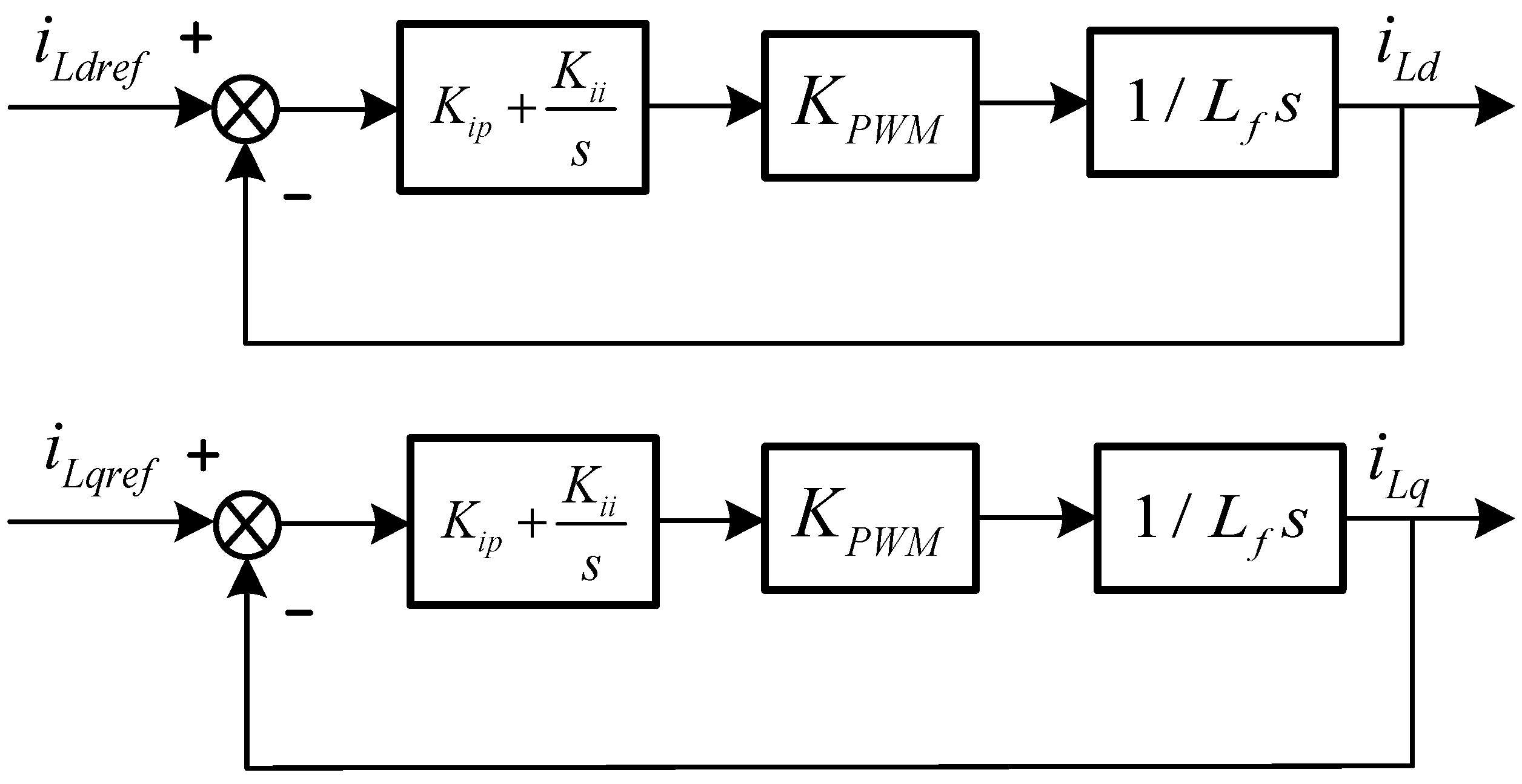
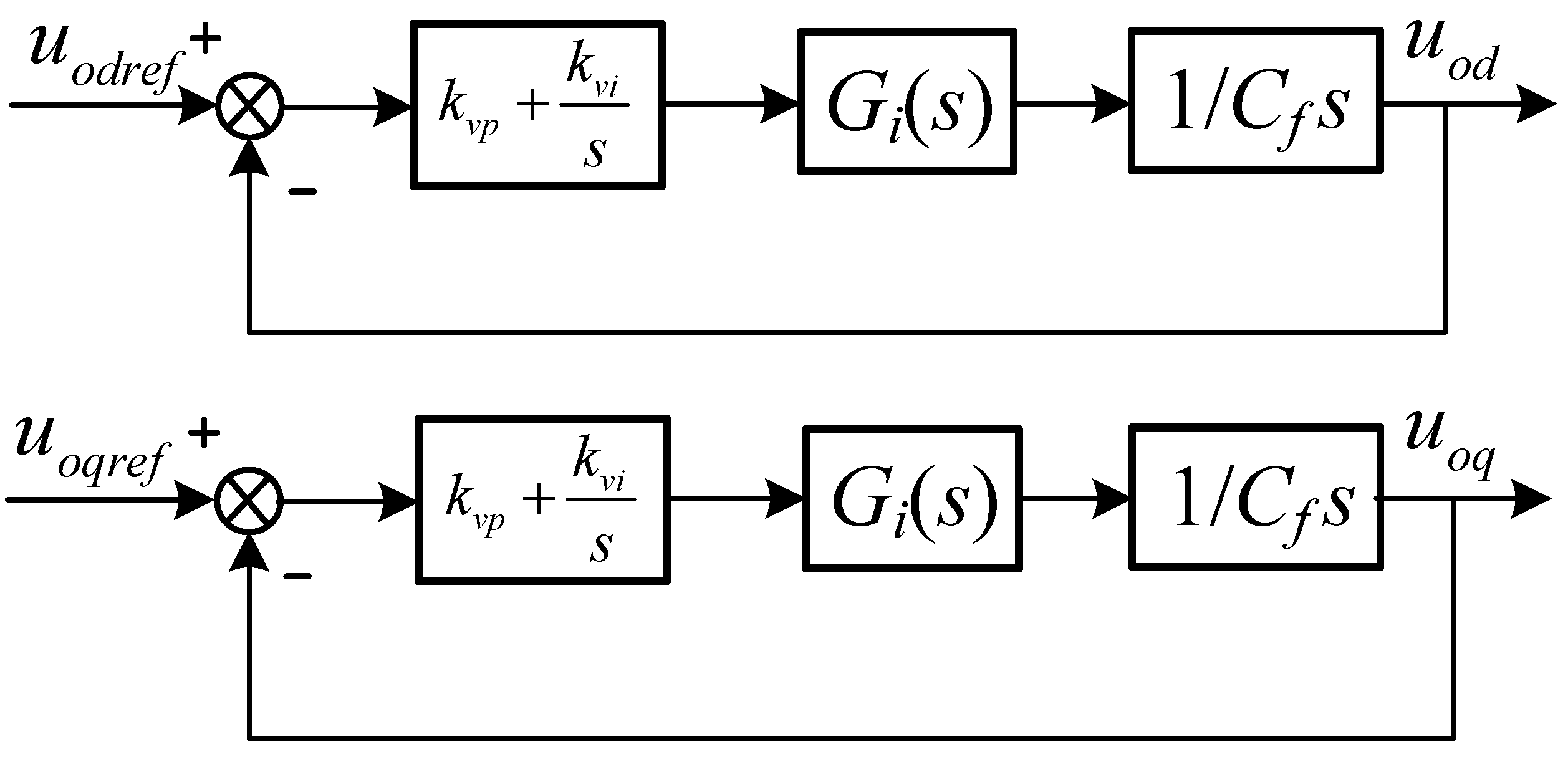
Figure 1. Each converter adopts the V/F control strategy, so the output voltage amplitude and the frequency are constant. The phase angle used for the coordinate transformation of the converter is generated by integration of frequency. Through the voltage and current dual loop modulation mentioned above, the converter outputs rated voltage amplitude and frequency for preparation of converters parallel.
After the V/F control is used, the converters will only produce circulating current due to phase angle inconsistency. Then the phase angle self-synchronization strategy is used to make the phase angle of output voltage of all converters in the system consistent.
As shown in 
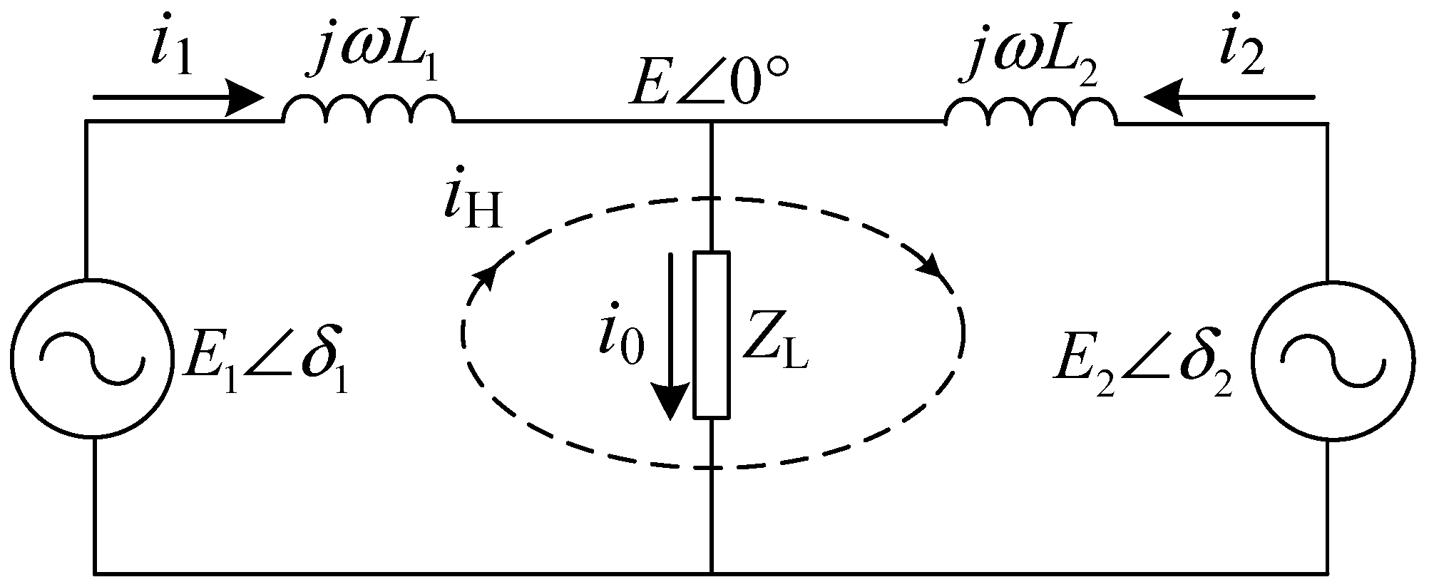
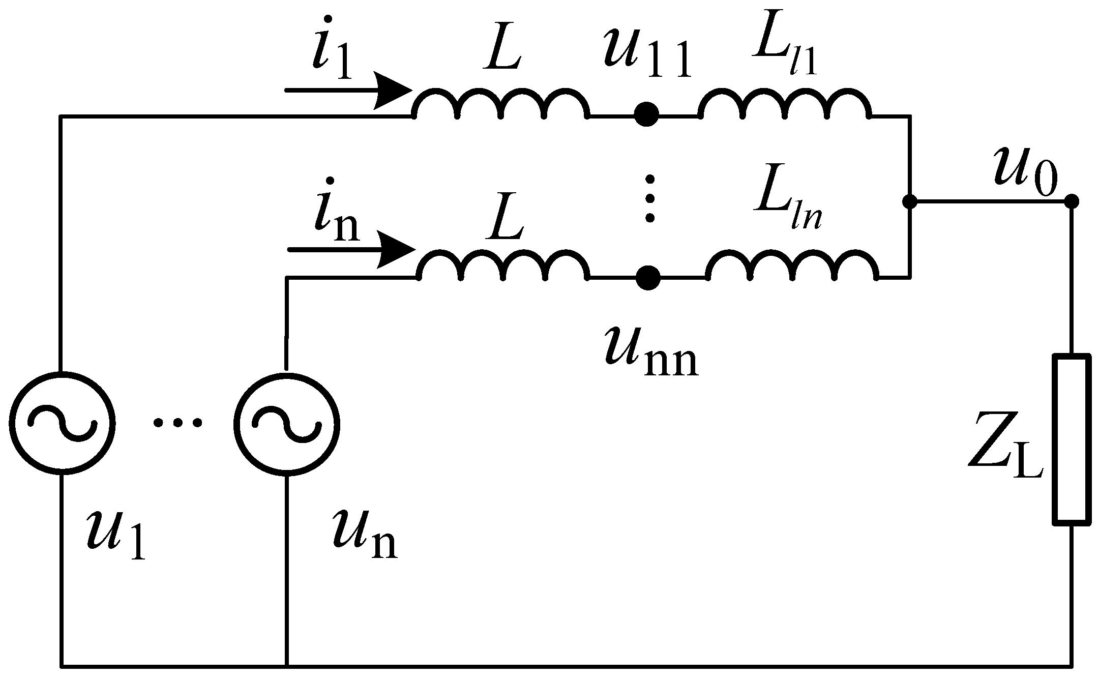
Figure 7, each converter in the parallel system uses the V/F control strategy. For each converter in the system, they have a common voltage signal, that is the load voltage. However, because the converter is in the distributed generation position, the distance between the converter to the load is far and the line distance is different. There is no communication line as well. Therefore, the converter has difficulty obtaining accurate load voltage as a common voltage reference. Therefore, a large inductance is added to the output port of the converter (see the next section for analysis). By doing this, the effect of line inductance Ll can be omitted, so the voltage drop ratio of the line inductance is reduced, therefore, the load voltage can be approximately equal to the voltage at the end of the converter, which can be taken as the phase angle reference.
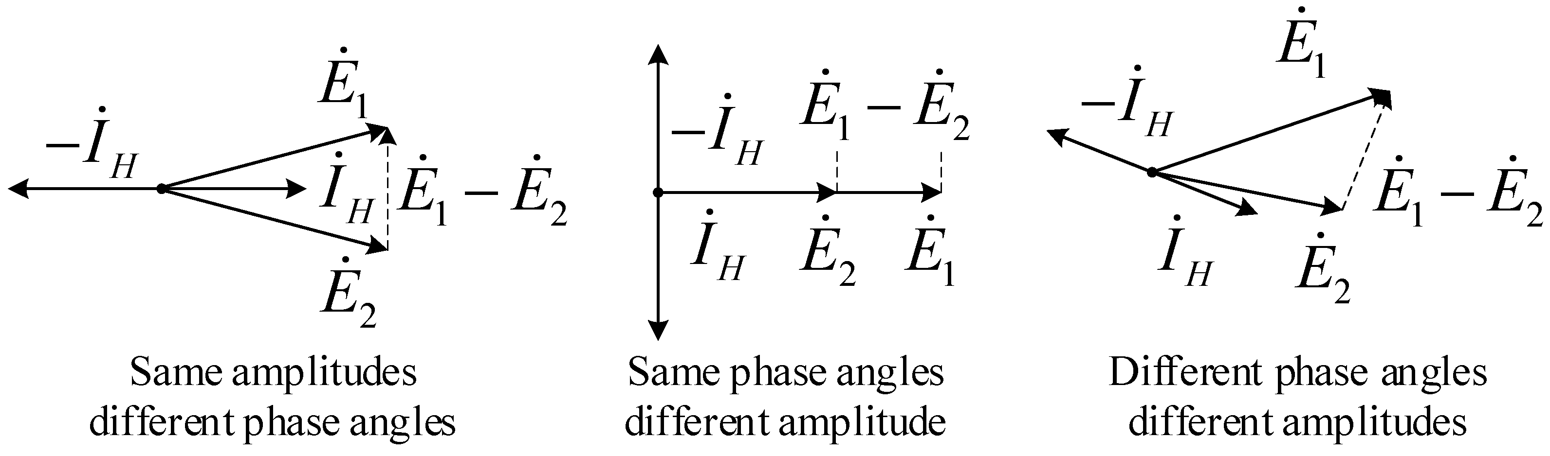
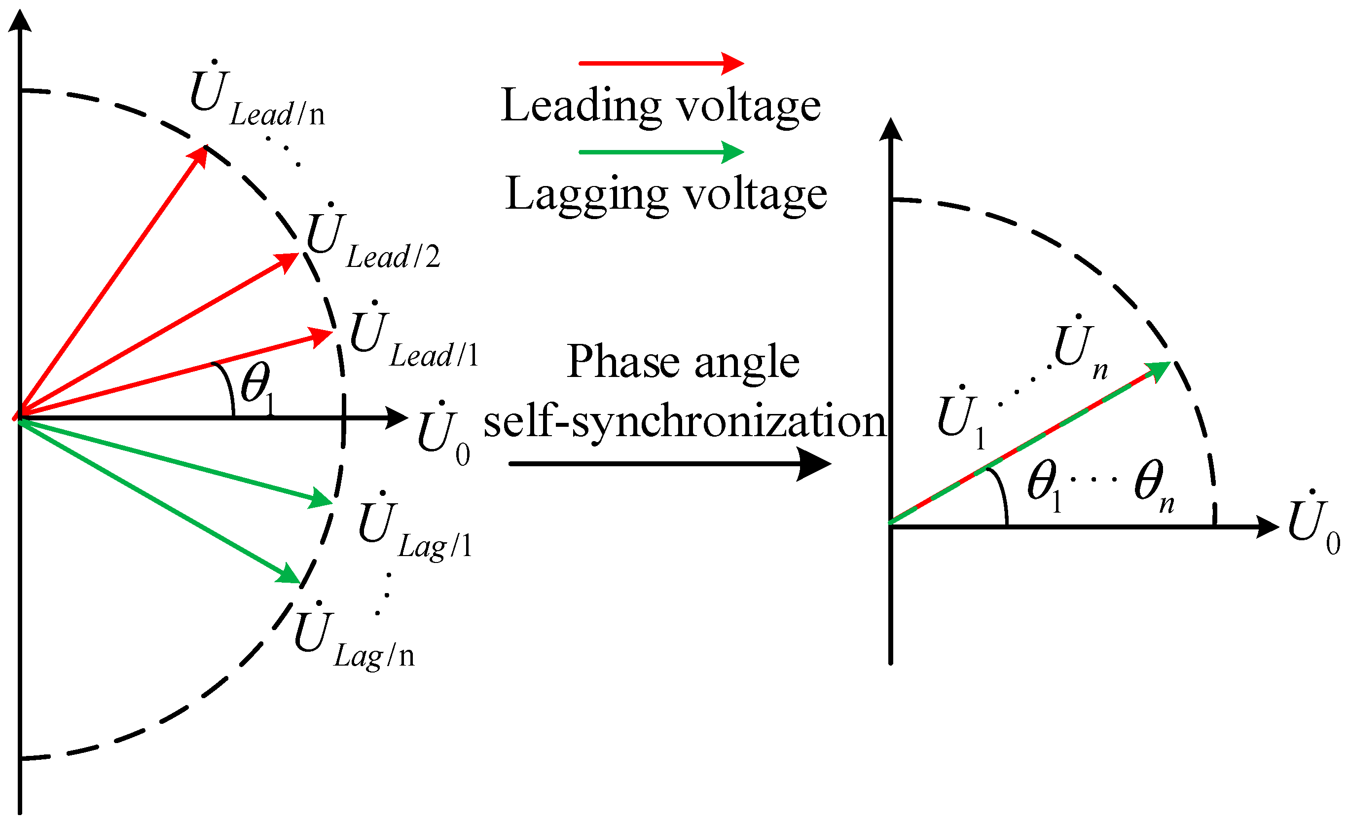
The output voltages of converters have a certain phase angle, φ1, φ2, φn. If the phase angle is different, the system will have a circulating current. Considering the transient performance of the converter system after stabilization, set the phase angle of U ˙ 0 to 0°, then the phase angle difference between the converters and the load voltage is θ1, θ2, and θn respectively.
The phase angle difference will cause circulating current between the converters when the amplitude and the frequency of their output voltage are same. In order to solve the problem of the difference of the phase angle between the output voltages of each converter, this paper proposes a phase angle self-synchronization strategy.
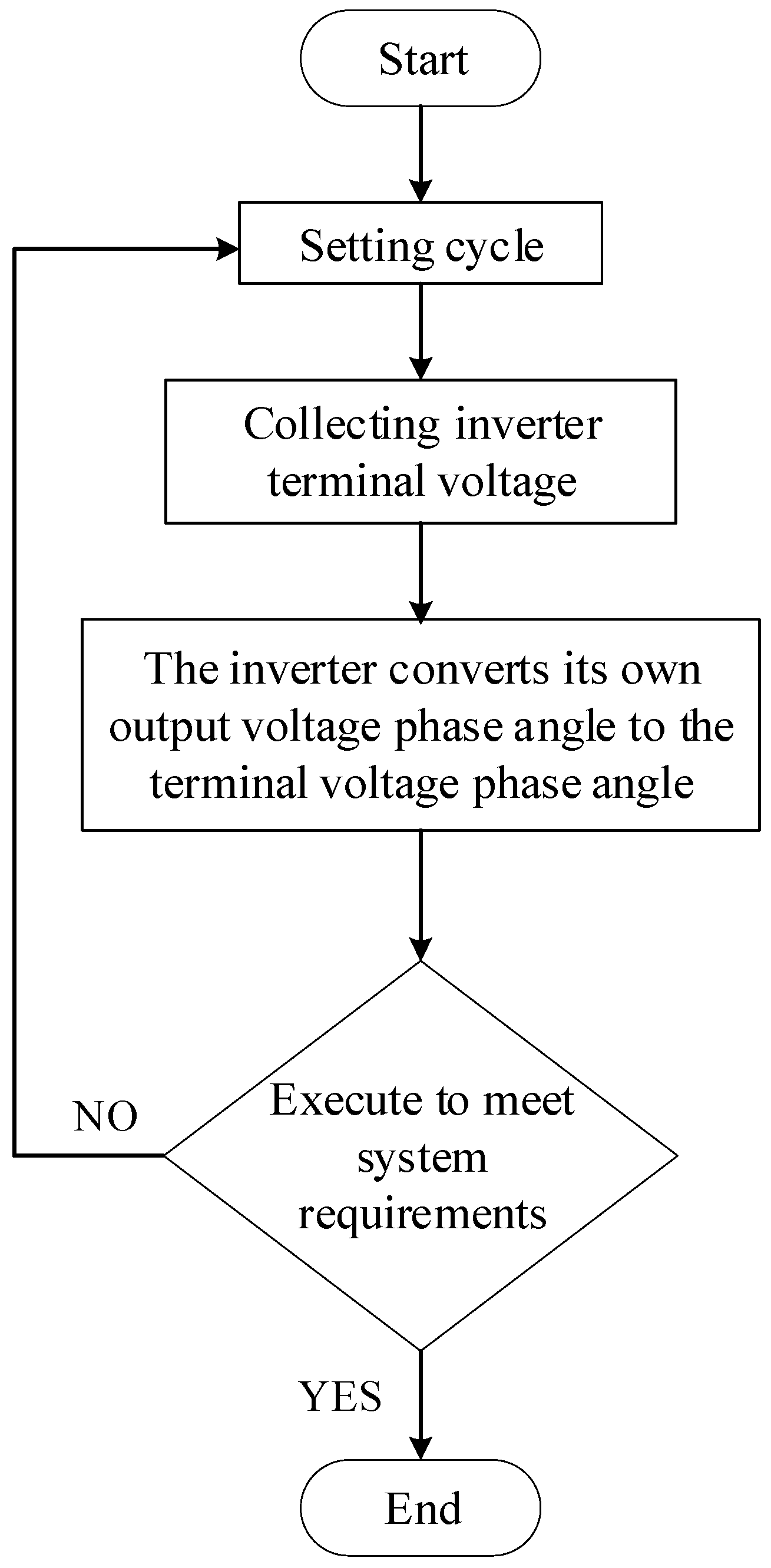
It can be seen from the above analysis that by adding a large inductance to the terminal of converter, the measured voltage of the load can be approximately replaced by the measured voltage of the terminal of converter. Each converter takes its own terminal voltage as the phase angle reference. That is, the phase angles of the output voltage of each converter in the system are converted into the phase angles of the measured converter terminal voltages of its own terminal, therefore, the output voltage phase angles of the converters are consistent, so that the parallel system has no circulating current and the load power is evenly distributed. The changing process of the phase angle of the output voltage of each converter in the system is as follows:
For a microgrid system, the converter in the microgrid uses PQ control when connected to the grid. After the failure of the large power grid, the microgrid enters the island mode, and the converter in the system needs to operate in parallel. According to the proposed parallel control strategy of the converter, after entering island mode, the converter in the microgrid uses the V/F control, at this time, difference of the output voltage lies in its phase angle, and this article also puts forward the phase angle self-synchronization to solve the problem.
First, considering the distance from the load to each converter is different, therefore, the circuit inductance from each converter to the load is different. In order to make scattered converters have a common benchmark phase angle in the case without the use of a communication line, this article put forward a solution by adding a large inductance on the end of each converter, to ignore the differences of inductance between each converter and the load. There is no need for a communication line or long-distance measurement route, for only the terminal voltage after the converter’s own large inductance needs to be measured.
After all the converters in the system collect the terminal voltage, the terminal voltage of each converter is approximately equal to the load voltage due to the large inductance, so each converter obtains a common voltage reference—load voltage. Phase angle self-synchronization strategy lies in that each converter converts its output voltage phase angle into the collected voltage phase angle at the converter end. Then the converter output voltage phase angle is consistent, at this point, the amplitude, frequency, and phase angle of all output voltages are the same, which achieve the goal of the stable operation of the parallel converter.
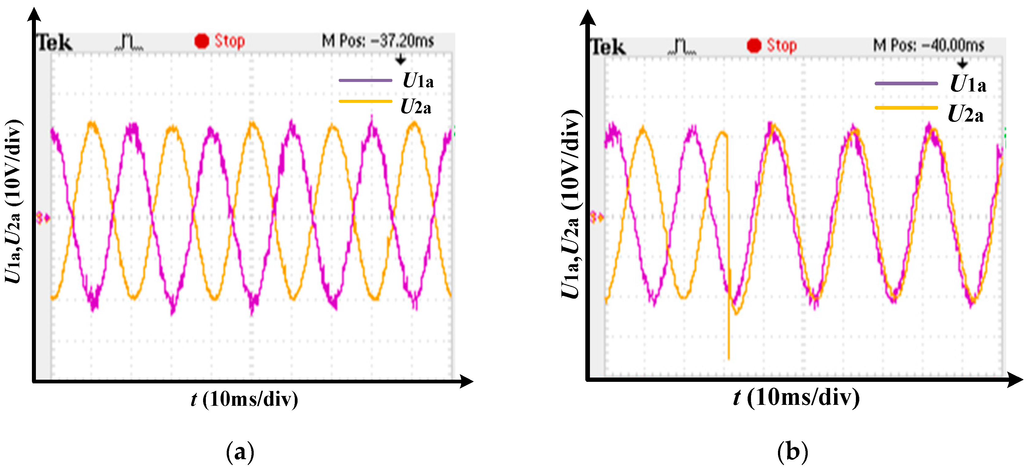
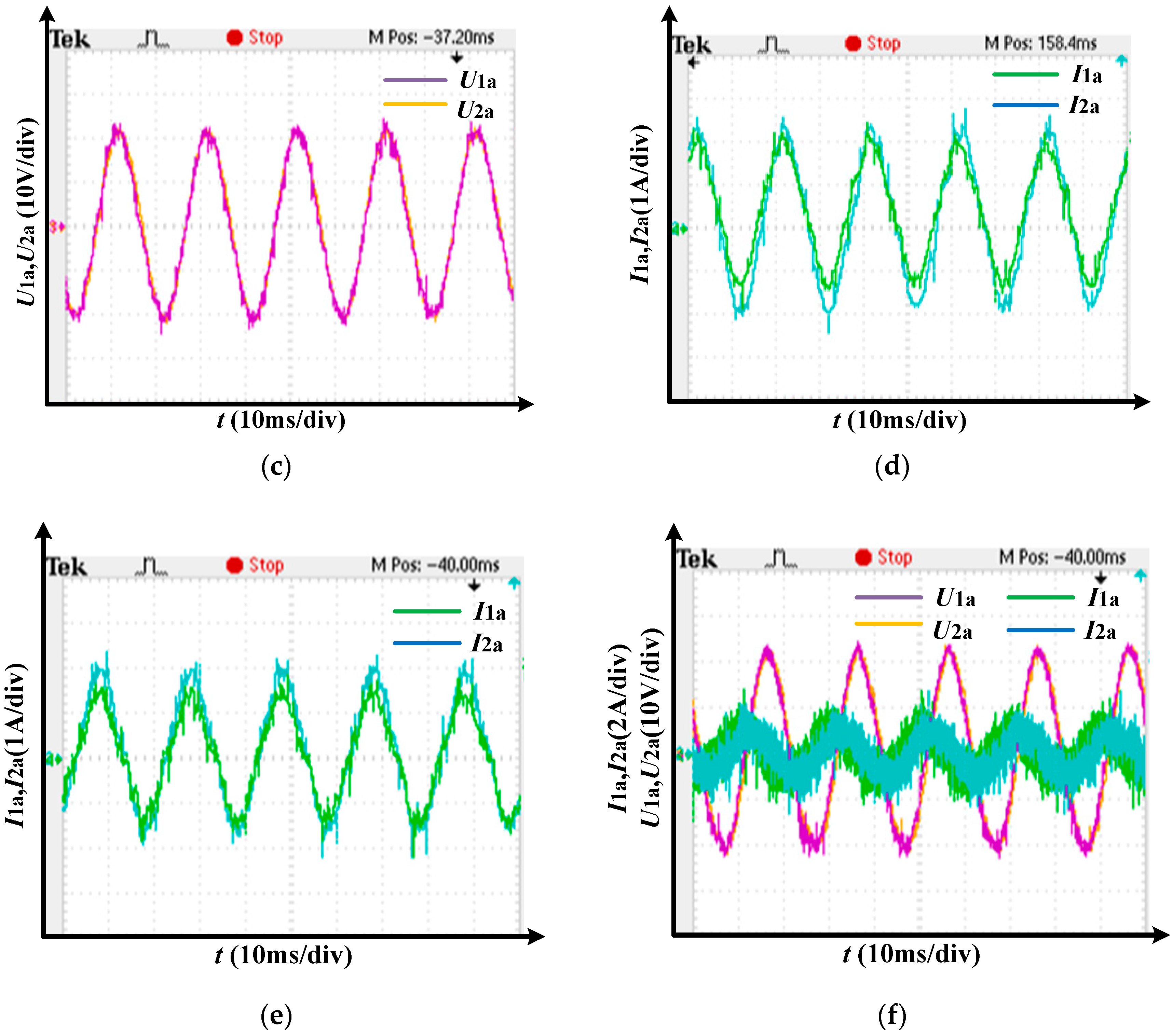
In actual operation, after the failure of the large power grid, the microgrid is transferred to island mode, which requires all converters to operate in parallel. Therefore, the converter parallel control strategy proposed in this paper is adopted. First of all, all converters in the microgrid use the V/F control mode, as shown in 
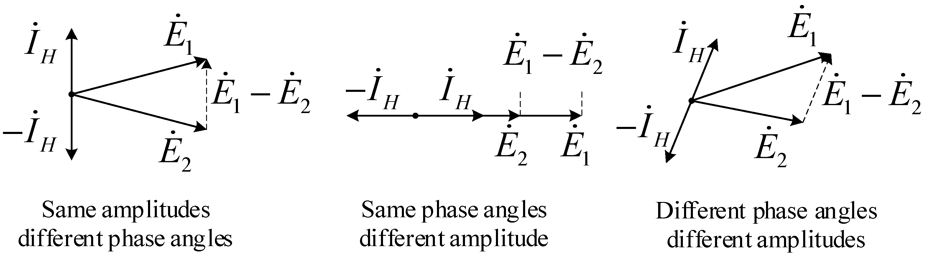
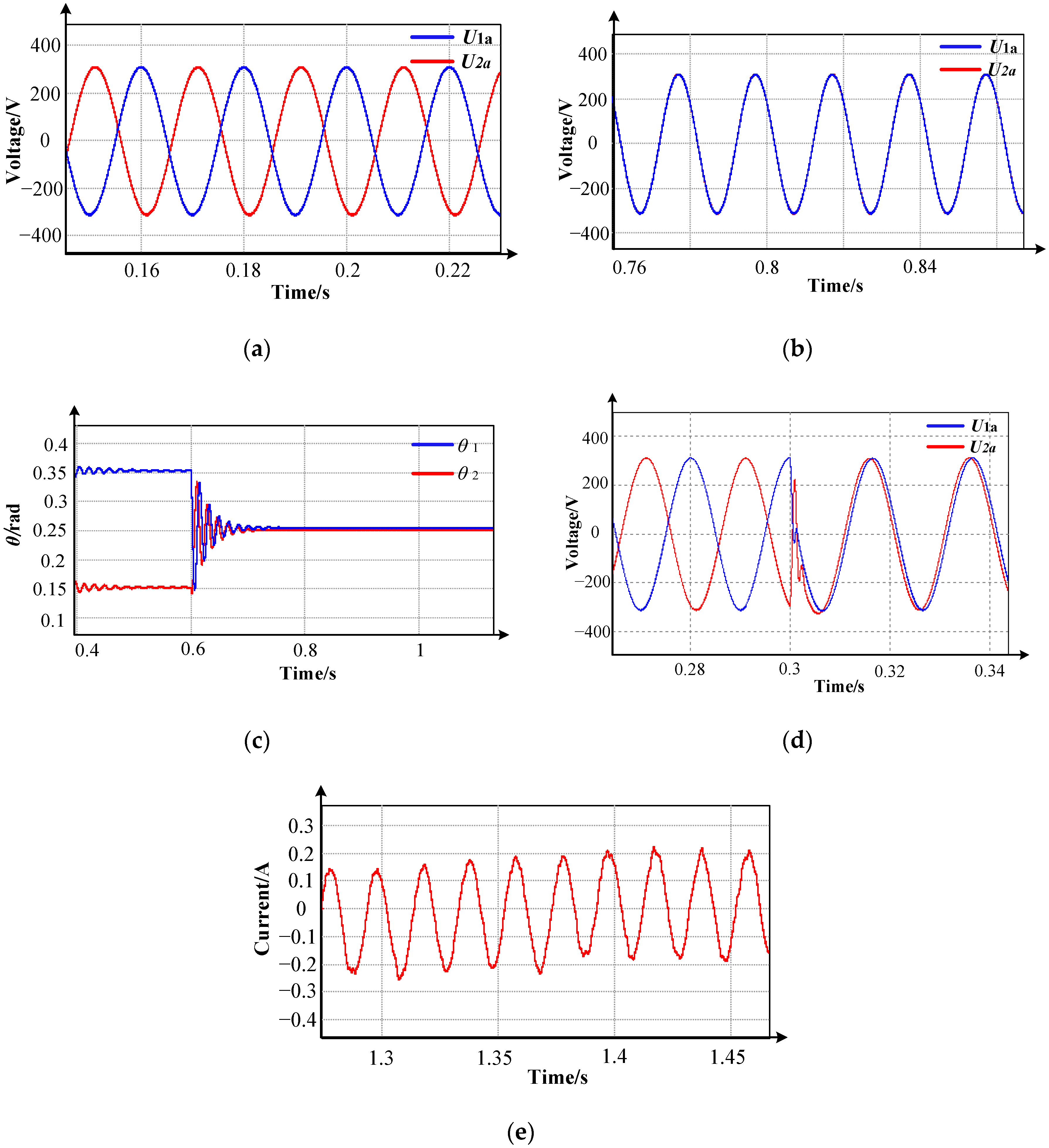
Figure 8, the amplitude and frequency of output voltage are the same, but the phase angles of the output voltage are not.
In Figure 8, U ˙ 0 represents the load voltage, which is approximately equal to the terminal voltage detected by each converter after adding large inductance. The red line in Figure 8 represents that the phase angle of the output voltage is ahead of the load voltage. The green line in Figure 8 represents that the phase angle of the output voltage is behind the load voltage. At this time, the phase angle of the output voltage in the system is different, and the system cannot run stably. The phase angle self-synchronization strategy proposed in this paper depends on the fact that each converter measures its own terminal voltage, which is approximately equal to the load voltage, as shown in Figure 8, which means each converter has a common phase angle reference. For example, the phase angle of the output voltage represented by the red line is ahead of the load voltage, and the converter detects the phase difference θ1 between its output voltage and the terminal voltage (which is approximately equal to the load voltage). The phase angle self-synchronization control strategy makes the phase angle difference between the output voltage of the converter and the terminal voltage to 0, that is, the phase angle of the output voltage is converted to the phase angle of the load voltage. Similar to the output voltage that is ahead of the load voltage, the green line represents the output voltage lags behind the load voltage, detected in the converter’s output voltage and load voltage phase angle difference, and the phase angle synchro control strategy eliminates the phase angle difference. As shown in Figure 8, after adjusting and stabilizing the system, the voltage and phase angle of output voltage of every converter come to a new balance. At this point, the amplitude, frequency, and phase angle of all output voltages in the microgrid are the same, achieving the purpose of stable operation of the system.
In summary, since the line distances between the converter and the load are different, the line inductance is not the same. By adding a large inductance to the converter end to ignore the line inductance, the load voltage is approximately equal to the terminal voltage of the converter. Replacing the remote load voltage with the terminal voltage of the converter not only eliminates the instability of the communication line, but also makes measurement extremely convenient. Accordingly, the phase angles of the output voltages are converted into the measured phase angles of the terminal voltages, so that the phase angles of the output voltages are identical. In addition, due to the V/F control strategy, the amplitude and frequency of output voltage are consistent. The phase angle, amplitude, and frequency of output voltage in the parallel system are equal, there is no circulating current between the converters, and the load power is distributed evenly.

3.2. Influence Analysis of Large Inductance and Its Design

3.2.1. Analysis of the Influence of Large Inductance on the System

The position of distributed generation is different. Therefore, the distance between converter and the load is also different, which lead to differences in line inductance. The common line parameters are shown in Table 1. The converter terminal voltage will have a big difference when no large inductance is added, affecting the operation of the parallel strategy of the converter.
As shown in Figure 7, taking two converters in parallel as an example, the system has no communication line. By adding a large inductance L to reduce the effect of the line inductance Ll, the voltage drop ratio of the line inductance is reduced, applying the superposition theorem to calculate the load voltage as shown in Equation (4):
U ˙ 0 = R j ω ( L + L l 2 ) R + j ω ( L + L l 2 ) R j ω ( L + L l 2 ) R + j ω ( L + L l 2 ) + j ω ( L + L l 1 ) U ˙ 1 + R j ω ( L + L l 1 ) R + j ω ( L + L l 1 ) R j ω ( L + L l 1 ) R + j ω ( L + L l 1 ) + j ω ( L + L l 2 ) U ˙ 2 .
The respective terminal voltages are as shown in Equations (5)–(7):
{ U ˙ 11 = U ˙ 0 + ( U ˙ 1 U ˙ 0 ) j ω L l 1 j ω ( L + L l 1 ) U ˙ 22 = U ˙ 0 + ( U ˙ 2 U ˙ 0 ) j ω L l 2 j ω ( L + L l 2 ) ,
U ˙ 11 = R j ω L R + j ω ( L + L l 1 ) R j ω ( L + L l 1 ) R + j ω ( L + L l 1 ) + j ω ( L + L l 2 ) U ˙ 2 + [ L L + L l 1 R j ω ( L + L l 2 ) R + j ω ( L + L l 2 ) R j ω ( L + L l 2 ) R + j ω ( L + L l 2 ) + j ω ( L + L l 1 ) + L l 1 L + L l 1 ] U ˙ 1 ,
U ˙ 22 = R j ω L R + j ω ( L + L l 2 ) R j ω ( L + L l 2 ) R + j ω ( L + L l 2 ) + j ω ( L + L l 1 ) U ˙ 1 + [ L L + L l 2 R j ω ( L + L l 1 ) R + j ω ( L + L l 1 ) R j ω ( L + L l 1 ) R + j ω ( L + L l 1 ) + j ω ( L + L l 2 ) + L l 2 L + L l 2 ] U ˙ 2 .
The ratio of large inductance to line inductance is as shown in Equation (8):
L l 1 = A L L l 2 = B L ( 0   < A   < 1 ,   0   <   B   < 1 )
U ˙ 11 U ˙ 22 = [ B R R + j ω L ( B + 1 ) + A R ( B + 1 ) R + j ω L ( B + 1 ) + ( A + 1 ) ] U ˙ 1 + [ A R R + j ω L ( A + 1 ) B R ( A + 1 ) R + j ω L ( A + 1 ) + ( B + 1 ) ] U ˙ 2 .
When there is no large inductance, the collected terminal voltage is:
U ˙ 11 = U ˙ 1 U ˙ 22 = U ˙ 2 .
The collected voltage difference between the two terminals is:
U ˙ 11 U ˙ 22 = U ˙ 1 U ˙ 2 .
Therefore, without large inductance, it is difficult for each converter to obtain a common voltage phase reference. If the large inductance is large enough, then A and B will approach 0, then the voltage relationship can be obtained as shown in Equation (11):
U ˙ 11 U ˙ 22 0 U ˙ 11 U ˙ 22 U ˙ 0 .
The conclusion can be obtained through analysis. For the multi-converter parallel system, the voltage of the converter is approximately the same, which can be used as the common phase angle reference. The addition of large inductance L will also reduce the influence of line inductance. Considering the influence of large inductance on terminal voltage, circulating current and load voltage respectively, the specific analysis is as follows.
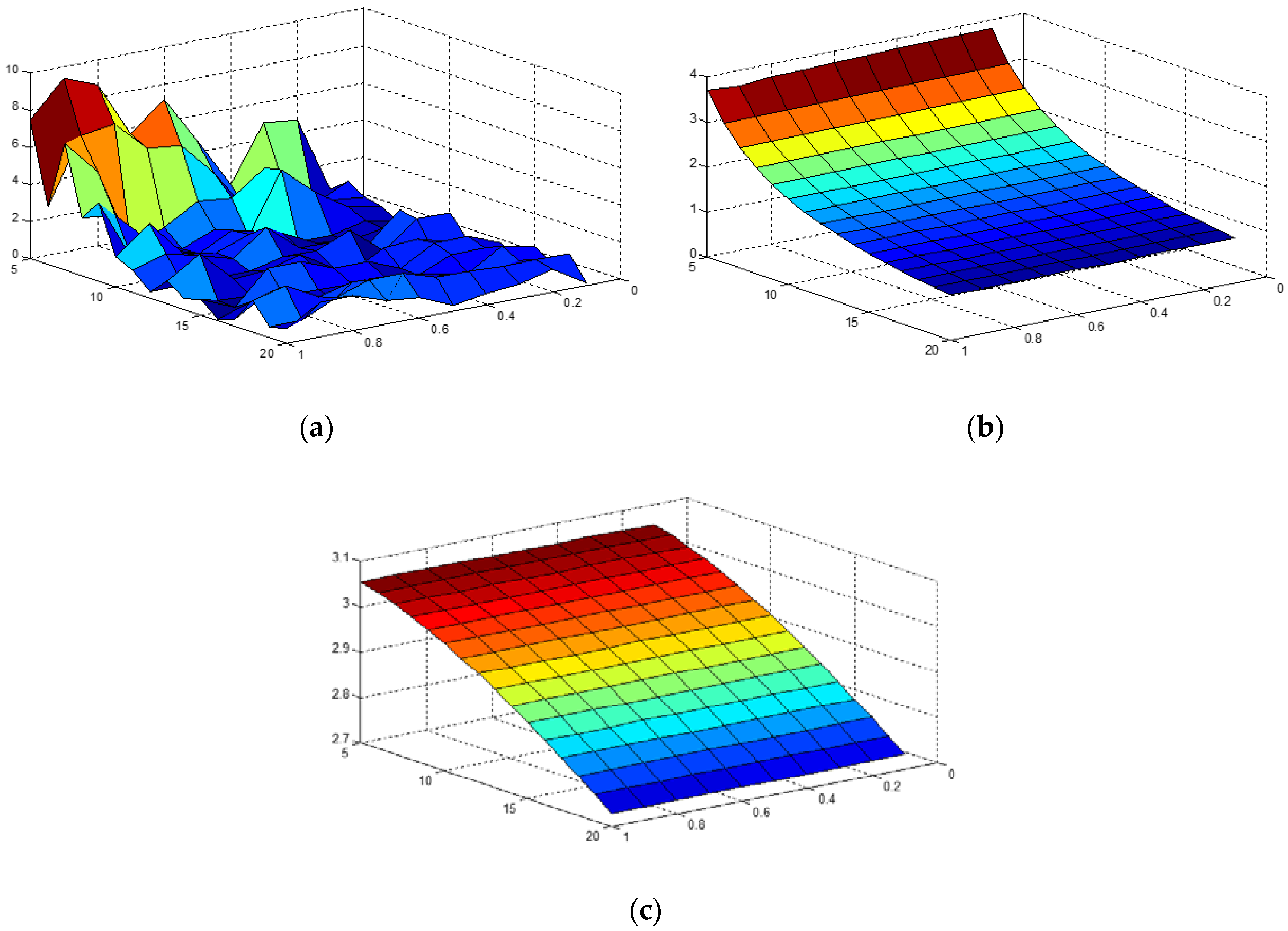
Figure 9 shows the influence of large inductance on terminal voltage difference, circulating current, and voltage amplitude change of the parallel system.
Where, the X-axis of Figure 9a represents the large inductance added at the converter end, rising from 5 to 10 mH. When x = 5, the system adds a 5 mH inductance at the converter end, and the maximum value is added to 10 mH. The Y-axis of Figure 9a represents the ratio of the line inductance between the two side converters and the load, rising from 0.1 to 1. When y = 0.1, it means that the distance between the two side converters and the load is 10 times different, and the line inductance is 10 times different. When y = 1, this means that the distance between the converters on both sides and the load line is equal, so is the circuit inductance. The z-axis of Figure 9a represents the voltage difference between the terminals of converters on both sides. In order to facilitate the observation of the graph, this paper used the per unit value. As can be seen from Figure 9a, the terminal voltage difference of the two side converters increases with the increase of the distance difference between the two side converters and the load line, the voltage difference between the terminals of the converters on both sides decreases with the increase of the large inductance added at the end of the converter, which proves that the large inductance has a close effect on the load voltage, and the addition of large inductance can effectively suppress the difference of the line inductance between the converters on both sides and the load.
Similar to Figure 9a, the X-axis of Figure 9b represents the large inductance added at the end of the converter, rising from 5 to 10 mH. The Y-axis of Figure 9b represents the ratio of the inductance of the line between the two side converters and the load, rising from 0.1 to 1. The z-axis of Figure 9b represents the circulating current of the converter parallel system. In order to facilitate the observation of the graph, the per unit value is used. As can be seen from Figure 9b, after the addition of large inductance at the converter end, the difference in line inductance between the two side converters and the load has little influence on the circulating current between the systems, and as the adding of large inductance at the converter end increases, the circulating current between the systems becomes smaller and smaller.
Similarly, the X-axis of Figure 9c represents the large inductance added at the end of the converter, rising from 5 to 10 mH. The Y-axis of Figure 9c represents the ratio of the inductance of the line between the two side converters and the load, rising from 0.1 to 1. The z-axis of Figure 9c represents the decreasing degree of output voltage of the converter after adding large inductance. In order to facilitate the observation of the graph, the per unit value is used. As can be seen from Figure 9c, after the addition of large inductance at the converter end, the difference in inductance between the two side converters and the load line has little influence on the decline of the output voltage of the converter. Moreover, as the large inductance at the converter end increases, the decline of the output voltage of the converter becomes greater and greater.
In summary, as the inductance increases, the difference in the terminal voltage of different converters in the system is gradually reduced, as the difference of the terminal voltage is smaller, the common phase angle reference obtained by each converter becomes more consistent, which not only facilitates the parallel operation of the converter, but also reduces the steady-state error of the parallel strategy.
As the inductance increases, the circulating current within the system gradually decreases, the magnitude of the load voltage drops more. It can be known that the addition of large inductance has advantages and disadvantages. While reducing the circulating current and reducing the voltage difference between the terminals of different converters, it also causes the load voltage to decrease. When designing a large inductance, it is necessary to take both aspects into consideration.

3.2.2. Large Inductance Design

As shown in Figure 7, taking two converters in parallel as an example, large inductance with two converter parallel systems is designed, and then extended to multiple converter parallel systems. The system circulating current is as shown in Equation (12), and then brought into the converter output voltage as shown in Equations (12)–(15):
I ˙ H = I ˙ 1 I ˙ 2 2 = U ˙ 1 U ˙ 0 j ω ( L + L l 1 ) U ˙ 2 U ˙ 0 j ω ( L + L l 2 ) 2 ,
{ U ˙ 0 = U ˙ 1 j ω ( L + L l 1 ) I ˙ 1 U ˙ 0 = U ˙ 2 j ω ( L + L l 2 ) I ˙ 2 ,
I ˙ H = ( U ˙ 1 U ˙ 2 ) L + U ˙ 1 L l 2 U ˙ 2 L l 1 + ( U ˙ 1 j ω ( L + L l 1 ) I ˙ 1 ) ( L l 1 L l 2 ) 2 j ω ( L + L l 1 ) ( L + L l 2 ) ,
I ˙ H = U ˙ 1 U ˙ 2 j ω ( L l 1 L l 2 ) I ˙ 1 2 j ω ( L + L l 2 ) .
Set the ratio of the circulating current to the rated current to a, to ensure that the system operation requirements are met, then design the value of L, and the details are shown in Equation (17).
I ˙ H = a I ˙ 1 ,
L = U ˙ 1 U ˙ 2 2 a j ω I ˙ 1 + L l 1 ( 2 a + 1 ) L l 2 2 a .
It can be seen from Equation (17) that the design of the large inductance L can be divided into two parts.
For the first part of Equation (17), there is a difference in the output voltage at the beginning of the system operation, which affects the system operation. The first side of Equation (17) is approximately 0 after the system is stable. Therefore, it is necessary to consider a certain size of current limiting inductor.
For the second part of Equation (17), depending on the line length of the distributed power supply to the load, since the line length is proportional to its line inductance, the greater the difference in line length between the two converters to the load, the larger the value of the large inductance L.
The value of a indicates the degree to which the system allows for circulating current, and can be designed to different values depending on the requirements of different systems. For multiple converter parallel systems, the distance from each converter to the load is different, and the inductance of the line is different. When designing the large inductance L, it is calculated based on the line inductance at the longest distance and the line inductance at the nearest distance. Then the line distances of other converters to the load are within the calculation interval, and the designed large inductance can meet the requirements of all converters.

4. Simulation Analysis and Experimental Verification

4.1. Simulation Analysis

In order to verify the correctness of the proposed converter parallel strategy, a simulation model is built based on the PSIM simulation platform. The specific simulation parameters are shown in Table 2.
For the simulation parameters shown in Table 2, the distance between the left converter and the load is 1000 m, while the distance between the right converter and the load is 500 m. This indicates that the distance between the two converters and the load is different, which can effectively test the role of large inductance. The line parameters shown in Table 1 can be used to obtain the line inductance of both sides. The inductance of the left side of the line is 0.264 mH, and the inductance of the right side of the line is 0.132 mH. Based on this, Equation (17) is used to calculate the value of large inductance.
Firstly, the right part of Equation (17) is calculated, that is, the value of large inductance that needs to be provided for the difference of circuit inductance. Let the allowable value of circulation be 1%, that is, a = 0.01. Then, put into the value of line inductance of both sides. The following formula can be obtained:
{ L l 1 = 0.264   m H L l 2 = 0.132   m H a = 0.01 ,
L l 1 ( 2 a + 1 ) L l 2 2 a = 0.264 ( 0.02 + 1 ) 0.132 0.02 = 6.468   m H .
As shown in Equation (19), in order to guarantee the circulating current is less, the minimum inductance required is 6.486 mH if the difference between the two sides of the inductance is neglected. As shown in Equation (17), the left half of inductance design is also considered in the inductance analysis process, including the influence of initial voltage inconsistency and margin. Considering that the large inductance needs to retain a certain margin based on 6.486 mH, we chose 10 mH large inductance in the simulation. The experimental results showed that the 10 mH large inductance effect is better. When the large inductance is lower than a certain degree, the system will be unstable, which proves the effectiveness of the large inductance design.
As shown in Table 2, in the simulation system, the left and right converters are all controlled by V/F control strategy. The inductance from one converter to the load is 0.264 mH, while the inductance from the other converter to the load is 0.132 mH, which means that the line distance is 1000 and 500 m. Different distances are used to characterize the difference in line inductance caused by the different distances from the distributed power source to the load.
The simulation system of two converters is built as shown in Figure 10. The converters are distributed in different locations depending on the location of the distributed power supply, so each converter uses a different DC power source. The converters in the parallel system use the V/F control strategy, and a phase angle self-synchronization part is added to synchronize the phase angles in the parallel system. A large inductance is added outside the filter to ignore the influence of the subsequent line inductance, which makes the converter terminal voltage approximately equal to the load voltage for phase angle synchronization operation.
In the simulation system shown in Figure 10, the two converters are operated in parallel using the proposed parallel strategy.
The results of parallel operation are shown in Figure 11. The curve in Figure 11a represents the initial state output voltage. The curve in Figure 11b represents the steady state output voltage. The curve in Figure 11c represents the change in phase angle difference. The curve in Figure 11d represents the transition process. The curve in Figure 11e represents the steady state circulating current.
As shown in Figure 11a, in the initial stage of the parallel operation of the converters, the output voltages of the two converters have the same amplitude and frequency, only the phase angles are different. As shown in Figure 11c, the parallel system adopts the proposed parallel strategy. The phase angles of the two converters are transformed based on the phase angle of the terminal voltage, so that the phase angles of the output voltages are consistent, as shown in Figure 11b. The phase angle variation of the output voltage of the two converters is shown in Figure 11d. The steady-state circulating current of the system is extremely small, as shown in Figure 11e.
The simulation results verify the correctness of the proposed parallel strategy of multiple converters. After the converter adopts the V/F control strategy, the amplitude and frequency of the output voltage are consistent. The phase angle self-synchronization strategy makes the phase angle of output voltages consistent, so the circulating current in the system is small, and the load power is evenly divided.

4.2. Experimental Verification

To verify the proposal, experimental results are presented in this section. There are two converters in the laboratory for parallel operation to verify the converter parallel strategy. Single converter adopts the V/F control strategy to ensure that the output voltages of the two converters have the same amplitude and frequency. The experimental system is described in Figure 12.
For experimental apparatus shown in Figure 12, the two converters are used to complete parallel experiments in the laboratory. Two converters supply power to the resistive load. The distance between the two side converters and the load is very short. The farthest distance between the left converter and the load is up to 2 m, and the farthest distance between the right converter and the load is up to 1 m. Therefore, the circuit inductance is small, which can be calculated by Equations (20) and (21).
{ L l 1 = 5.29 × 10 4   m H L l 2 = 2.64 × 10 4   m H a = 0.01 ,
L l 1 ( 2 a + 1 ) L l 2 2 a = 5.29 × 10 4 ( 0.02 + 1 ) × 2.64 × 10 4 0.02 = 0.013   m H .
Considering the voltage levels on the left and right sides and the impact of the initial circulating current, we connected a large inductance of 1.54 mH in series behind the filter inductance of the converter in the experiment, which means the difference of line inductance can be ignored. The experimental results also prove the effectiveness of large inductance and the correctness of the parallel strategy.
According to the proposed parallel strategy of the converters, all converters in the system adopt the V/F control strategy to make the amplitude and frequency of the output voltage consistent. Then the converter adopts the phase angle self-synchronization strategy to automatically adjust the phase angle difference. The phase angle self-synchronization flow chart is as follows in Figure 13:
Based on the converter parallel experimental platform shown in Figure 12, the converter uses the phase angle self-synchronization strategy shown in Figure 13. The experimental results are shown in Figure 14.
As shown in Figure 14a, in the initial stage of the parallel operation of the converters, the output voltages of the two converters have the same amplitude and frequency, but the phase angles are different. As shown in Figure 14c,d, the parallel system adopts the proposed parallel strategy. The output voltage phase angles of all converters change, and the output current is gradually consistent. Finally, the output voltages of the two converters have the same amplitude, frequency, and phase angle, as shown in Figure 14b. As shown in Figure 14e, after the phase angle self-synchronization action, the output voltage and output current of the two converters are consistent. Amplifying its output current shows that the steady-state output current of the two converters is almost the same, and the circulating current is very small, as shown in Figure 14f.
Similar to the previous simulation results, the experimental results verify the validity of the proposed multi-converter parallel strategy.

5. Conclusions

In this paper, a new parallel control strategy of converter was proposed to realize the parallel operation of converters with no communication line in a microgrid.
1. The converter in microgrid uses the PQ control strategy when worked under the gird connected condition. When a large power grid fails, the converters are required to be connected in parallel in the case of grid isolation. According to the above situation, the solitary offline parallel control scheme in the parallel system of the converter is put forward. The V/F control is used in the converters of the system, so the amplitude and frequency of output voltage are same and there lies a difference in the phase angle.
2. To eliminate the difference of phase angle of the converter’s voltage, a phase angle self-synchronization scheme was proposed. In this scheme, in order to allow each converter at a long distance to obtain an identical voltage reference, a large inductance is used to make the terminal voltage approximately equal to the load voltage. The terminal voltage of each converter was measured as the voltage reference, and the phase angle of this voltage was used for phase angle self-synchronization operation. After phase angle self-synchronization operation, the amplitude, frequency, and phase angle of the output voltage are consistent, and the requirements of parallel operation are reached.
3. During actual operation, the distances from each converter to the load are different in the microgrid, and this difference of distances leads to the difference of the line inductance. According to the proposed parallel scheme, a large inductance needs to be added in the end of the converter to ignore the difference caused by the various circuit distances. A design scheme about how to add the large inductance was put forward, and the function and influence of the large inductance were analyzed respectively according to the distance difference of the circuit.
As described in the introduction, the existing converter parallel control schemes mainly include centralized control, distributed control, master-slave control, 3C control, power line communication control, and droop down control. By comparing with the existing schemes, the advantages of the converter parallel control scheme proposed in this paper are as follows:
1. Compared with the control scheme with a communication line, the converter parallel control scheme proposed in this paper does not need to use a communication line, so it can greatly improve the safety and stability of the parallel system. On the other hand, this scheme does not need a demodulation chip and other additional equipment, which increases the economy of the system.
2. The parallel scheme proposed in this paper has a simple implementation principle, and the program is easy to install on a single converter unit, which is convenient to operate and has certain universality.
3. The converter parallel control scheme proposed in this paper is relatively reliable and has strong anti-interference, which is conducive to the stable, reliable, and safe operation of the parallel system.

Author Contributions

The authors contributed as follows: conceptualization, G.Z.; methodology, G.Z. and H.Y.; software, H.Y.; validation, G.Z. and H.Y.; formal analysis, H.Y.; investigation and resources, H.Y.; data curation, H.Y.; writing—original draft preparation, G.Z. and H.Y.; writing—review and editing, H.Y.; supervision, G.Z.; project administration, G.Z.

Funding

This research was funded by the Fundamental Research Funds for the Central Universities (2018MS008).

Conflicts of Interest

The authors declare no conflict of interest.

References

  1. Alam, M.N.; Chakrabarti, S.; Ghosh, A. Networked Microgrids: State-of-the-art and Future Prospectives. IEEE Trans. Ind. Inf. 2018, 99, 1238–1250. [Google Scholar] [CrossRef]
  2. Deng, Q.; Sun, P.; Hu, W.; Czarkowski, D.; Kazimierczuk, M.K.; Zhou, H. Modular Parallel Multi-Inverter System for High-Power Inductive Power Transfer. IEEE Trans. Power Electron. 2019, 99, 9422–9434. [Google Scholar] [CrossRef]
  3. Chen, T.; Lee, C.K.; Hui, R. A General Design Procedure for Multi-parallel Modular Grid-tied Inverters System to Prevent Common and Interactive Instability. IEEE Trans. Power Electron. 2019, 34, 6025–6030. [Google Scholar] [CrossRef]
  4. Tan, K.T.; Peng, X.Y.; So, P.L.; Chu, Y.C.; Chen, M.Z.Q. Centralized Control for Parallel Operation of Distributed Generation Inverters in Microgrids. IEEE Trans. Smart Grid 2012, 3, 1977–1987. [Google Scholar] [CrossRef]
  5. Shankar, Y.R.; Mishra, M.K. Instantaneous Symmetrical Component Theory based Parallel Grid Side Converter Control Strategy for Microgrid Power Management. IEEE Trans. Sustain. Energy 2018, 10, 682–692. [Google Scholar]
  6. Li, Y.; Liu, Q.; Hu, S.; Liu, F.; Cao, Y.; Luo, L.; Rehtanz, C. A Virtual Impedance Comprehensive Control Strategy for the Controllably Inductive Power Filtering System. IEEE Trans. Power Electron. 2016, 32, 920–926. [Google Scholar] [CrossRef]
  7. Shafiee, Q.; Guerrero, J.M.; Vasquez, J.C. Distributed Secondary Control for Islanded Microgrids—A Novel Approach. IEEE Trans. Power Electron. 2013, 29, 1018–1031. [Google Scholar] [CrossRef]
  8. Wu, Y.; Wu, Y.; Guerrero, J. Distributed Coordination Control for Suppressing Circulating Current in Parallel Inverters of Islanded Microgrid. IET Gener. Transm. Distrib. 2019, 13, 968–975. [Google Scholar] [CrossRef]
  9. He, Z.; Xing, Y. Distributed Control for UPS Modules in Parallel Operation with RMS Voltage Regulation. IEEE Trans. Ind. Electron. 2008, 55, 2860–2869. [Google Scholar]
  10. Cheng, Y.J.; Sng, E.K.K. A novel communication strategy for decentralized control of paralleled multi-inverter systems. IEEE Trans. Power Electron. 2006, 21, 148–156. [Google Scholar] [CrossRef]
  11. Tu, C.-C.; Xiong, S.; Xiao, F.; Lan, Z. Master-Slave Control Strategy for Parallel Operation of Multiple DC Micro-Source Based on Current Tracking. Power Syst. Technol. 2017, 41, 2205–2213. [Google Scholar] [CrossRef]
  12. Guerrero, J.M.; Hang, L.; Uceda, J. Control of Distributed Uninterruptible Power Supply Systems. IEEE Trans. Ind. Electron. 2008, 55, 2845–2859. [Google Scholar] [CrossRef]
  13. Wu, T.-F.; Chen, Y.-K.; Huang, Y.-H. 3C strategy for inverters in parallel operation achieving an equal current distribution. IEEE Trans. Ind. Electron. 2000, 47, 273–281. [Google Scholar]
  14. Chiang, S.J.; Lin, C.H.; Yen, C.Y. Current limitation control technique for parallel operation of UPS inverters. In Proceedings of the IEEE Power Electronics Specialists Conference, Aachen, Germany, 20–25 June 2004; pp. 1922–1926. [Google Scholar]
  15. Piboonwattanakit, K.; Khan-ngern, W. Design of two parallel inverter modules by circular chain control technique. In Proceedings of the IEEE Power Electronics and Drive Systems, Bangkok, Thailand, 27–30 November 2007; pp. 1518–1522. [Google Scholar]
  16. Su, J.; Zhang, Y.; Chen, M. Power Line Communication with Network Transmission Data Loss Based on Learning Control. Int. J. Wirel. Inf. Netw. 2018, 25, 314–322. [Google Scholar] [CrossRef]
  17. Duan, S.; Jian, C.; Feng, F.; Chen, J. Wireless parallel operation Scheme of Inverters based on power line communication. Autom. Electr. Power Syst. 2003, 27, 28–31. [Google Scholar]
  18. He, Z.; Wang, X.; Xing, Y.; Ma, Y. Pre-synchronization control for parallel inverters based on power line communication. In Proceedings of the IEEE Power Electronics Specialists Conference, Rhodes, Greece, 15–19 June 2008. [Google Scholar]
  19. Arafat, M.N.; Elrayyah, A.; Sozer, Y. An Effective Smooth Transition Control Strategy Using Droop-Based Synchronization for Parallel Inverters. IEEE Trans. Ind. Appl. 2015, 51, 2443–2454. [Google Scholar] [CrossRef]
  20. Trivedi, A.; Jain, D.K.; Singh, M. A modified droop control method for parallel operation of VSI’s in microgrid. In Proceedings of the IEEE Innovative Smart Grid Technologies-Asia, Bangalore, India, 10–13 November 2014. [Google Scholar]
  21. Wu, T.; Liu, Z.; Liu, J.; Wang, S. A Unified Virtual Power Decoupling Method for Droop Controlled Parallel Inverters in Microgrids. IEEE Trans. Power Electron. 2016, 31, 5587–5603. [Google Scholar] [CrossRef]
  22. Yao, W.; Chen, M.; Matas, J.; Guerrero, J.W. Design and Analysis of the Droop Control Method for Parallel Inverters Considering the Impact of the Complex Impedance on the Power Sharing. IEEE Trans. Ind. Electron. 2011, 58, 576–588. [Google Scholar] [CrossRef]
  23. Chethan, R.D.; Gaonkar, D.N.; Guerrero, J.M. Improved P-f/Q-V and P-V/Q-f Droop Controllers for Parallel Distributed Generation Inverters in AC Microgrid. Sustain. Cities Soc. 2018, 41, 421–442. [Google Scholar]
  24. Zhong, Q.-C.; Wang, Y.; Ren, B. UDE-Based Robust Droop Control of Inverters in Parallel Operation. IEEE Trans. Ind. Electron. 2017, 64, 7552–7562. [Google Scholar] [CrossRef]
Figure 1. Single converter topology.
Electronics 08 01110 g001
Figure 2. Simplified current loop block diagram.
Electronics 08 01110 g002
Figure 3. Simplified voltage loop block diagram.
Electronics 08 01110 g003
Figure 4. Converter’s parallel operation.
Electronics 08 01110 g004
Figure 5. Output voltage and circulating current of parallel systems when output impedance is inductive.
Electronics 08 01110 g005
Figure 6. Output voltage and circulating current of parallel systems when output impedance is resistance.
Electronics 08 01110 g006
Figure 7. N converters operating in parallel.
Electronics 08 01110 g007
Figure 8. Phase angle conversion process using phase angle self-synchronization strategy.
Electronics 08 01110 g008
Figure 9. The effect of large inductance on parallel systems: (a) Terminal voltage difference; (b) change in circulating current; (c) change in amplitude.
Electronics 08 01110 g009
Figure 10. Simulation system.
Electronics 08 01110 g010
Figure 11. Converter parallel strategy simulation results: (a) initial state output voltage; (b) steady state output voltage; (c) change in phase angle difference; (d) transition process; (e) steady state circulating current.
Electronics 08 01110 g011
Figure 12. Experimental setup.
Electronics 08 01110 g012
Figure 13. Phase angle self-synchronization strategy flow chart.
Electronics 08 01110 g013
Figure 14. Converter parallel strategy experimental results: (a) initial state output voltage; (b) the transient process of the output voltage; (c) steady state output voltage; (d) the transient process of the output current; (e) steady state output current. (f) Output voltage and current of two converters after stabilization.
Electronics 08 01110 g014aElectronics 08 01110 g014b
Table 1. Typical line parameters.
Type of LineR (Ω·km−1)wL(Ω·km−1)R/wL
Low voltage line0.6420.0837.70
Medium voltage line0.1610.1900.85
High voltage line0.0600.1910.31
Table 2. System simulation parameters.
ParameterLeft ConverterRight Converter
Amplitude and Frequency311 V and 50 Hz311 V and 50 Hz
Line length1000 m500 m
Line inductance0.264 mH0.132 mH
Large inductance10 mH10 mH
Filter L, C3 mH and 100 uF3 mH and 100 uF
Switching Frequency10 kHz10 kHz

