Article

A Wideband Terahertz Transmissive Polarization Manipulator Based on Metasurfaces

1
School of Electronic and Information Engineering, Beihang University, Beijing 100191, China
2
Beijing Key Laboratory for Microwave Sensing and Security Applications, Beihang University, Beijing 100191, China
*
Author to whom correspondence should be addressed.
Electronics 2019, 8(10), 1068; https://doi.org/10.3390/electronics8101068
Submission received: 14 August 2019 / Revised: 14 September 2019 / Accepted: 18 September 2019 / Published: 20 September 2019
(This article belongs to the Collection Millimeter and Terahertz Wireless Communications)

Abstract

:
Wideband and multifunction operation for THz polarization manipulating devices has been desired for a wide range of applications. In this paper, a novel wideband transmissive type polarization manipulator based on metasurfaces is proposed in the THz region. The designed metasurface acts as a multifunctional polarization manipulator, performing linear to circular polarization conversion (LCPC) for relative bandwidth 43.9% (0.94 THz to 1.47 THz) for incident x/y polarizations and a wideband bandpass filter with relative bandwidth 67% (0.713 THz to 1.4346 THz) for incident slant (xy) polarizations. Wideband LCPC operation is achieved using a unique diagonal symmetric structure based on a bilayered metasurface. In order to confirm the validation of proposed results, electromagnetic simulation was carried out in two industry-standard software packages, HFSS and CST, using frequency domain and time domain solvers, respectively. Close agreement between numerical results depicts the validity and reliability of the proposed design. Polarized wave trajectory, equivalent microscopic circuit, physical mechanisms, and impact of different geometrical parameters on the performance is investigated. To the best of our knowledge, this is the first polarization manipulator based on bilayered metasurfaces. The same structure can be used as for LCPC and the transmit reject filter for THz wireless communication, including THz satellite communications, the future of communication. Moreover, they can be used in THz imaging and biomolecular control devices.

1. Introduction

Terahertz (THz) electromagnetic waves ranging from of 0.1 THz to 10 THz located between the microwave and infrared bands is a rapidly growing technology. With the advancement in THz sources and detectors [1,2,3,4], THz technology has been investigated in wide applications such as spectroscopy [5] imaging [6], remote sensing [6,7] and telecommunications [8]. Polarization of an electromagnetic field is the direction in which the electric field oscillates while traveling through the medium. In wireless communications, the choice of polarization of the antenna depends upon the application as well as the medium. Manipulation of this polarization state has been used in a wide range of applications, including wavefront control and optical communication [9,10]. Circular polarized THz beams have been used in biomedical imagining because of the different behavior of chiral structures of biomolecules towards a circular polarized THz beam. For example, Bessel beams can be used to control the motion of biomolecules for applications such as biosensing and drug delivery [11,12].
For THz wireless communication, including satellite communication, circularly polarized waves are preferred because of their lower sensitivity towards multipath fading as compared to linearly polarized waves. There are two ways to achieve circular polarization: using circularly polarized antenna; or converting linearly polarized waves generated by an antenna into circularly polarized waves using LCPC. The latter is sometimes advantageous when we have readily available linearly polarized antenna. Polarization manipulation can be categorized into two types, reflection-based and transmission-based. The former uses a ground conducting plate to reflect electromagnetic waves, whereas the latter consists of bilayered or multilayered, differently patterned conducting patches. Stealth technology is a major application for reflection-based manipulation [13,14,15]. Transmission-based manipulation is used in transmission systems where transmitted waves and incident waves need to be aligned.
Terahertz wave engineering to obtain polarized waves has been explored using metasurfaces numerically [16,17,18,19] or experimentally [20] for a wide range of applications, including cloaking, camouflage, amplifiers, isolators, duplexer antenna systems, and mixers. Birefringent structures have been used to convert one type/state of polarization into another polarization state/type. Examples include waveplates [21,22,23,24,25,26,27], liquid crystals [28,29,30], and wood and paper [31,32]. Such structures are not only bulky as they have thickness much larger than the operating wavelength, but also have complex fabrications. Metamaterials, chiral metamaterials, and quasiperiodic planar arrays of subwavelength elements have attracted research attention because of their distinguished properties such as asymmetric transmission and polarization conversion with tenability and flexibility [33,34,35]. Metasurfaces classified as 2D metamaterials have become a hot research topic because of their low profile. Phase manipulation of THz waves using metasurfaces has been investigated in recent years [36,37,38], including linear to circular polarization conversion capability due to their smaller profiles [36,39,40,41,42,43,44]. Graphene-based wideband LCPCs have also been investigated to dynamically control the manipulation [39,40,41]. However, in all these polarization converters [39,40,41,42,43,44,45,46], most of the researchers have worked on reflection-based polarization conversion. Recently, Jiang et al. numerically investigated an excellent and broadband LCPC using reflective layers [47]. Such converters cannot be used where incident linear waves and outgoing required circular waves need to be aligned with each other.
Metasurfaces can be classified into chiral and anisotropic metasurfaces. Chiral metasurfaces use chirality inclusions to break the mirror symmetry of the structure. This concept of chiral metasurfaces has been used in manipulating polarization states in transmission modes to achieve linear to circular polarization conversion in both microwave and optical frequencies [48,49,50]. However, most chiral metasurfaces suffer from the disadvantage of narrow bandwidth due to their resonant characteristics. Anisotropic metasurfaces have been used for wideband polarization control in reflection mode [39,42,43]. Broadband transmission-based polarization manipulation is still a challenging problem. H. L. Zhu et al. [51] quoted transmissive linear to circular polarization conversion in the microwave frequency range using a single layer of metasurfaces but the bandwidth achieved was just 12.5%. Similarly, different structures for LCPC operation have been proposed [52,53,54] using single/double-layered structures, but the maximum bandwidth achieved was 15%. Moreover, for the structures proposed in [53,54], the diagonal portion used to obtain right-handed circular polarization (RHCP) wave was the opposite to that for left-handed circular polarization (LHCP). Such LCPCs [40,51,52,53,54] limit the choice of selection when a wide range of operation and both LHPC and RHCP are required.
The wideband operation for LCPCs has been achieved using multilayered metasurfaces. For example, Sayed, et al. [55] proposed wideband transmissive LCPC using subwavelength capacitive and inductive patches and achieved 40% bandwidth; however, the structure was based on six layers of metallic patches which is too complicated to fabricate. Bao-Qin Lin et al. [56] achieved 40% linear to circular polarization conversion but they used three layers of metasurfaces. Gerarardo et al. [57] proposed a design technique for broadband LCPC in reflection and transmission mode but the structure working in transmission mode works over 17% bandwidth and is based on three layers stacked together. Baoqin Lin et al. [58] proposed a wideband LCPC in the microwave band that maintains an axial ratio of 3 dB within 33% bandwidth; however, the structure consists of three layers stacked between two dielectric spacers.
Substantial attention is being devoted to developing terahertz satellite links for geostationary satellites [59]. Filters play a vital role in any communication system, including THz communication. Scientists have proposed different frequency-selective surface (FSS)-based filtering structures, such as free-standing resonant mesh filters, inverse metal resonant grids, and split ring resonators [60,61,62,63,64]. Han et al. [63] proposed a THz bandpass filter consisting of a metal–dielectric–metal (MDM) sandwich with a periodic slot structure. Chiang et al. [64] reported an ultrawide THz bandpass filter based on a metamaterial. Transmit reject filters (also called receive filters) in THz wireless communication are essential for receiver systems that require high isolation at transmitting frequency. Since receive systems do not deal with high power, the typical requirements for transmit reject filters include low insertion loss in the passband, small size, and high rejection in the transmit band. These filters had been implemented in waveguide topology in microwave and millimeter-wave bands [65]. In the THz band, where Y-band waveguides can have fabrication issues, a solution based on low-profile metasurfaces is an attractive choice when high power is not a concern.
In this paper, a metasurface-based structure is proposed which serves two purposes: transmission-based linear to circular polarization conversion covering 43.9% bandwidth, and a wideband transmit reject filter with 67% fractional bandwidth. The proposed structure is, to the best of our knowledge, the widest among any transmissive type LCPC [40,48,49,50,51,52,53,54,55,56,57,58,59,60] that works with both horizontal (x) and vertical (y) polarization and converts the transmitted wave into LHCP and RHCP, respectively, within 3 dB of the axial ratio. Moreover, with slant (xy) polarizations, the proposed structure behaves as a transmit reject filter.
This paper is organized as follows: Section 2 of the paper describes the design of the proposed polarization manipulator, including an equivalent electric circuit. Section 3 compares the simulation, analysis, physical mechanisms, and impact of different structural parameters on the performance and filtering behavior of the proposed device with other state-of-the-art designs. The conclusion is presented in Section 4.

2. Materials and Methods

It is well known that the basic polarization manipulation properties of metasurfaces originate from cross-coupling between electric and magnetic field resonances in the presence of an incident wave with a specific polarization state. In order to obtain LCPC, the unit-cell structure of the metasurface needs to be tailored to the cross-coupling effects. This helps to obtain the orthogonal components of transmitted waves with different or the same polarizations. In the past, many diagonal symmetric/semisymmetric structures have been proposed for this purpose [36,52,53,54,57,66]. However, they were either based on single or double resonating elements or were single-layered with different structures for LHCP and LHCP [53,54]. Such structures cannot achieve a wide band of operation. Here, a bilayered diagonal symmetric structure consisting of multiresonating structures is proposed. The proposed structure is shown in Figure 1. It consists of two sheets of conductors with a substrate layer sandwiched in between. Flexible polyimide quartz with a dielectric constant ɛr of 4.0 and dielectric loss tangent of 0.004 was used as a substrate [67]. Gold was used as a conductor and was characterized by a conductivity σ dc = ϵ 0 ω p 2 τ . ω p is the plasma frequency and τ is the relaxation time for scattering [63]. The shaded region in Figure 1b shows the conductor layer which consists of two parts: the outer part is a square ring with a conductor width of ( a l ) / 2 and the inner part consists of a large square of dimensions b × b with three identical squares of dimensions c × c eliminated from it along its diagonal. The bottom layer is identical to the top layer. The optimized parameters for the unit cell were determined as follows: a = 50 µm, b =30 µm, c = 12 µm, d = 5 µm, l = 47.5 µm. Full-wave electromagnetic (FWEM) simulation was carried out in the standard electromagnetic software—High Frequency Structure Simulator (HFSS). The design was simulated using master–slave boundary conditions. Floquet ports at the input and output of the unit cell were applied so that an infinite periodic array structure may be realized. In order to validate the performance of the proposed structure, the optimized unit cell was resimulated in the Computer Simulation Technology (CST) time-domain solver.
The electric equivalent circuit for the proposed structure is as shown in Figure 2 at the microscopic level where two adjacent cells will be represented by coupled capacitors [68]. We have considered thin metasurfaces as an impedance sheet with negligible resistance to simplify the equivalent circuit. When the incident wave is x-polarized, the equivalent microscopic circuit is as shown in Figure 2a. The outer square ring’s upper and lower arm behave as inductors, represented as ‘L1’. The eliminated square on the top right and bottom left corners behave as capacitors (C1) aligned with inductors (L2), whereas the diagonal eliminated patch acts as a capacitor (C2). The conductor patch at the top left and bottom right is modeled as inductor and is represented as L3. Inductances of L3 will be lower than inductances of L1 and L2. Coupling between two adjacent unit cells in the horizontal direction is represented by C3.
With an incident y polarized wave, we considered two unit cells in the y-direction with the equivalent circuit shown in Figure 2b. Now, only left and right arms of the outer square ring will be effective and are represented by the inductance ‘L1’. Since the width of the conductor remains the same, the value of this inductance will be L1. The eliminated squares on the top right corner and bottom left corners behave as capacitors (C4) aligned with the inductors (L4). The diagonal eliminated patch will act as capacitor (C2). The values of these inductors and capacitors will be different from C1, L2, and C2, respectively, due to different direction of the incident electric field. The conductor patch at the top left and bottom right is modeled as an inductor and is represented as L5. Inductances of L5 will be lower than inductances of L1 and L4 because of the larger width of the conducting patch. Coupling between two adjacent unit cells in the vertical direction is represented by C6, where C6 = C3.

3. Results and Discussion

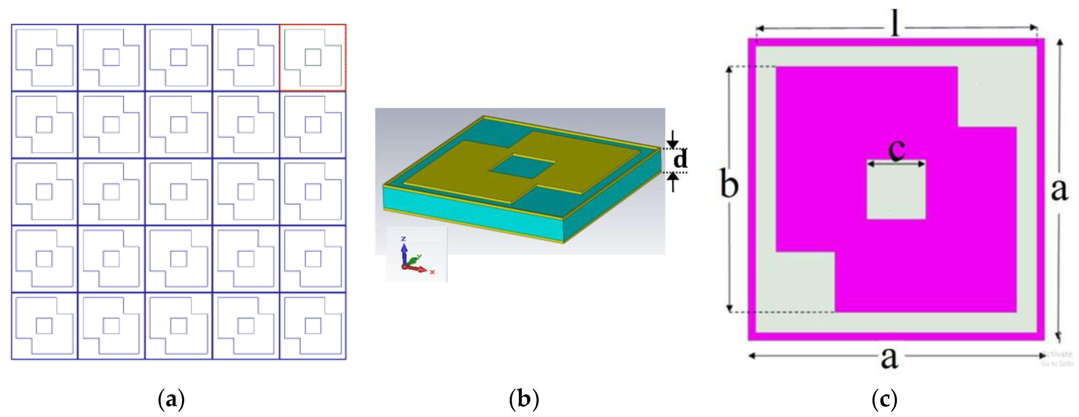
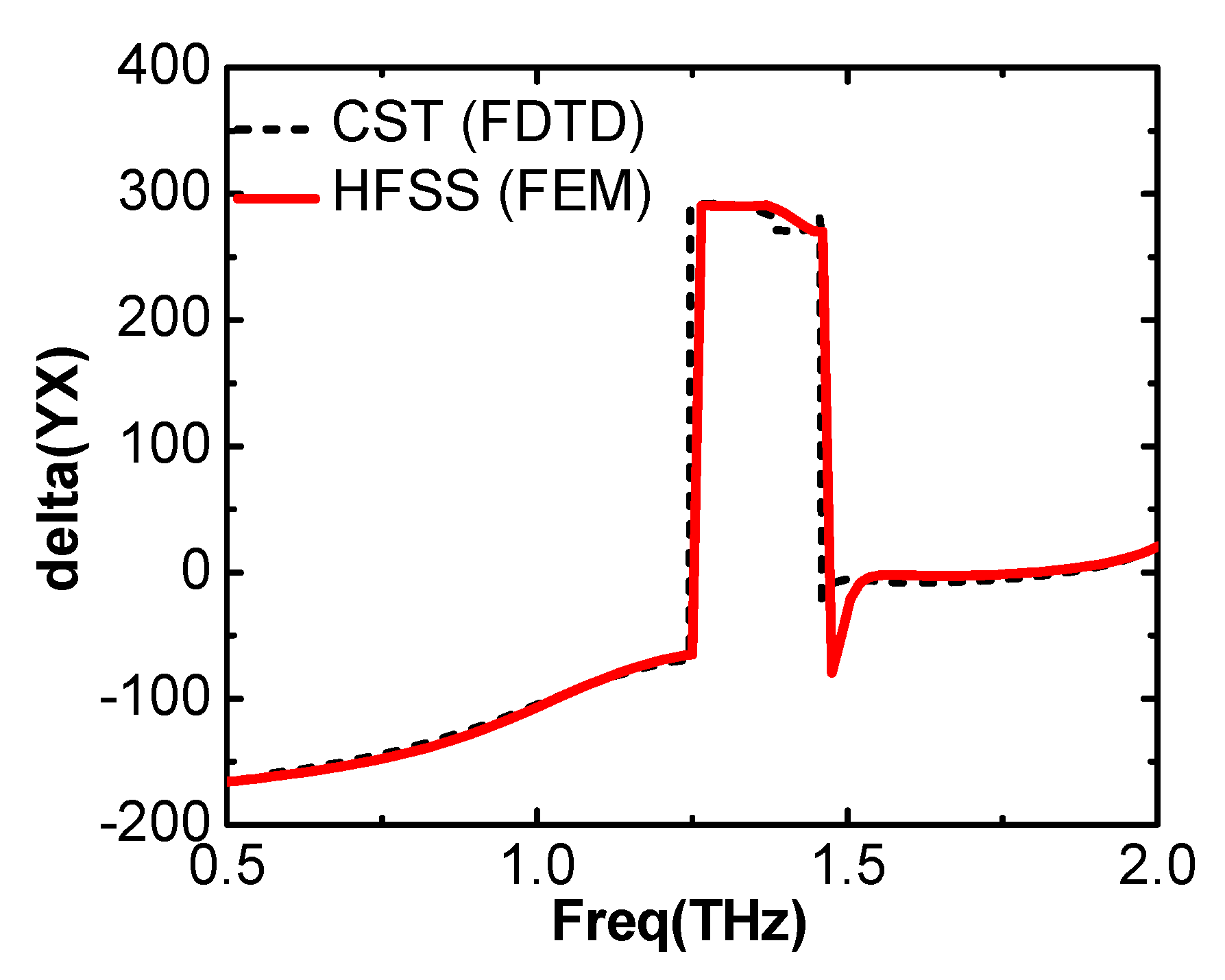
3.1. Simulation and Analysis of the LCPC

In order to validate the performance of the proposed structure, the optimized unit cell was resimulated in the Computer Simulation Technology (CST) time-domain solver. Close agreement between HFSS and CST results validate the performance of the proposed structure. Figure 3a,b depict the transmission characteristics for the incident x-polarized and y-polarized wave traveling in the ‘-z’ direction in CST and HFSS.
The phase difference between the transmitted x-polarized and y-polarized components with an incident x-polarized wave is shown in Figure 4. The phase difference between the two polarized components from 0.94 THz to 1.47 THz is close to −90° or +270°. There is a slight mismatch between the two results obtained from the two software packages. This might be due to different computational techniques; HFSS works on the finite element mesh (FEM) method, whereas CST’s time-domain solver works on the finite difference time domain (FDTD) method to solve Maxwell Equations. Two similar responses from different computational techniques confirm the validity of our proposed design; therefore, further simulations were carried out in HFSS.
In order to understand the operation of the LCPC, we consider a plane horizontal (x polarized) wave traveling in the ‘-z’ direction. The incident wave can be expressed as Equation (1). The magnitudes of this incident wave are expressed in Equation (2).
E x i = E x i e x
E x i = E 0 e j k z
The transmitted wave can be expressed as the sum of two components, i.e., x-polarized and y-polarized, as shown in Equation (3):
  E t = E x t e x + E y t e y = t x x e j φ x x E 0 e j k z e x + t x y e j φ x y E 0 e j k z e y
t x x = E x t E x i
t x y = E y t E x i
where txx and txy represent transmission coefficients for x to x and x to y polarization conversion as shown in Equations (4) and (5), respectively. φ x x and φ x y are phase angles corresponding to txx and txy, respectively. Since the proposed structure has an anisotropic structure, the magnitudes and phases for x-polarized and y-polarized transmitted waves may be different. However, if for a certain frequency range these transmission coefficients become comparable and their phase angles are 90° apart, i.e., txx = txy and   φ x y = 2 n π ± π / 2 , n being an integer. This would be the condition where linear horizontal (x-polarized) wave will be converted into a perfectly circularly polarized wave. In order to describe the transmission conversion performance for the proposed structure, we calculate the axial ratio for the transmitted wave as in Equation (6):
A R = ( | t x x | 2 + | t x y | 2 + a | t x x | 2 + | t x y | 2 a ) 1 / 2
where ‘a’ can be calculated from Equation (7) as:
a = | t x x | 4 + | t x y | 4 + 2 | t x x | 2 | t x y | 2 cos ( 2 φ x y )
For a perfect LCPC, AR should be 1 (0 dB); however, in most of the systems, a 3 dB value of the axial ratio is acceptable.
It is clear from Figure 3a that in the frequency range from 0.94 THz to 1.47 THz, the transmission coefficient magnitudes are comparable, whereas the phase difference between them is −90° or +270° with ±10° variation. Therefore, the condition for linear to circular polarization is fully met at some frequencies. For a range of frequencies, it partially fulfils the requirement (in this case, the transmitted wave will be slightly elliptically polarized). However, the performance criterion for linear to circular transmission conversion (axial ratio within 3 dB) is maintained. Furthermore, the y component of the transmitted wave is ahead of the x component; hence, the transmitted wave is left-handed circularly polarized (LHCP). In addition, the proposed unit cell behaves equally well for the incident vertical (y polarized) wave, resulting in a RHCP transmitted wave for 0.94 THz to 1.47 THz. Figure 5 shows the axial ratio for the incident x polarized and y polarized waves.
To evaluate the performance of the transmitted polarized wave, Stokes parameters were calculated using Equations (8) to (11) [41]:
I = | t x | 2 + | t y | 2
Q = | t x | 2 | t y | 2
U = 2 | t x | | t y | cos ( d )
V = 2 | t x | | t y | sin ( d )
where d is the phase angle between the x and y components of the transmitted wave. Ellipticity for the polarized wave can be calculated as Ellipticity = V / I . Ideally, ellipticity as ‘−1’ and ‘+1’ depicts that the transmitted wave is RHCP and LHCP, respectively. Furthermore, polarization conversion efficiency (PCE) can be defined as [39]:
PCE = | E x t | 2 + | E y t | 2 | E x i | 2 = | t x x | 2 + | t x y | 2
Figure 6 shows the ellipticity and PCE for the transmitted wave. It is clear from Figure 6 that from 0.94 THz to 1.47 THz, ellipticity is greater than 0.8. Moreover, the reasonable polarization conversion efficiency is observed from 0.94 THz to 1.47 THz. The value of ellipticity is found to be 0.97 at 1.085 THz and 0.999 at 1.445 THz, respectively, which is very good.

3.2. Physical Mechanism for LCPC Operation

The proposed structure is an anisotropic structure which has dual diagonal symmetry. In such a case, the incident x-polarized wave generates transmitted x and y polarized waves and the incident y polarized wave generates transmitted x and y waves. To explain the physical phenomenon behind the proposed LCPC, we considered the surface current vectors at any two frequency points within the LCPC operation, f1 and f2: f1 = 1.085 THz and f2 = 1.454 THz. Figure 7 shows the surface current distribution with the incident x-polarized wave at different frequencies. Figure 7a shows surface current vectors in the top metasurfaces, whereas Figure 7b shows surface current vectors in bottom (ground) surface at f1. There are two parts of the metasurfaces that contribute to the linear to circular polarization conversion. One is the outer square ring and the other is the inner metallic tri-square eliminated square patch. Figure 7a shows that the current in the unit cell’s metal square ring travels antiparallel to the current induced in the ground surface. This will generate circulating current loops inside the substrate. It will give rise to magnetic resonance and equivalent magnetic dipoles will be created under x-polarized incident waves [69]. Figure 7c,d show surface current vectors on the top metasurfaces and ground surface, respectively, at f2. It is clear that besides contribution of outer square ring, the innermost eliminated square patch contributes to the wide bandwidth and the currents are parallel in the top and bottom surfaces. The outer square ring and tri-square eliminated square patch both give rise to electric resonance due to their parallel currents [42]. To support our work, the electric field distribution between the four adjacent cells of the array structure was investigated.
Figure 8a,b show the electric field distribution at 1.085 THz and 1.454 THz, respectively. It is clear from Figure 8a that the electric field concentrates on the outer layer of the tri-square eliminated patch, whereas, for 1.454 THz, the electric field is very strong and is concentrated on the whole tri-squares eliminated patch with the innermost square having high electric field strength. This multiresonance structure validates the wider bandwidth of the polarization converter.
In order to enhance the idea of wide-band LCPC conversion, we calculate the frequency-dependent impedance for the unit circuit shown in Figure 2a under x-polarized incident wave:
Z x ( w ) = 1 2 jwL 2 + 1 2 jwC 1 + 1 2 jwL 3 + 1 2 jwL 2 + 1 jwC 2 + 1 jwC 3
Due to the complex and un-matched frequency-dependent impedance of the unit cell in Equation (13), the proposed structure behaves differently at different frequencies. It has been shown in Figure 7a,b that at f1 =1.085 THz, circulating currents flow inside the substrate which shows that adjacent unit cells in the x-direction are playing the role of a parallel circuit at f1. At f2 =1.45 THz, surface currents in the top and bottom surface are parallel, which predicts the role of the series circuit for adjacent unit cells in the x-direction. Thus, two different modes exist at two frequencies, which also supports the unit’s wide-band operation. Similarly, the frequency-dependent impedance for the unit cell with a y-polarized incident wave as shown in Figure 2b can be expressed as:
Z y ( w ) = 1 2 jwL 1 + 1 1 2 jwL 5 + 1 2 jwL 4 + 1 jwC 5 + 2 jwC 4 + 1 jwC 3
To investigate the transmitted wavefront trajectory, we introduce the vector wave Equation as:
x 2 t x x   + y 2 t x y 2 x y t x y t x x cos φ y x = sin 2 φ y x
The wave-front trajectory curves at different frequencies are as shown in Figure 9. It is clearly shown that transmitted waves at 1.085 THz and 1.175 THz are circular, whereas waves at 1.387 THz and 0.995 THz are elliptically polarized. This limitation is because at some frequencies, the transmitted x- and y-components are unequal. This results in an axial ratio greater than 0 dB, hence indicating that the transmitted waves are not exactly circularly polarized. However, the performance criterion for the circular polarization is considered to be within 3 dB of axial ratio where the nonzero value of the axial ratio corresponds to slight elliptical polarization which can be considered as partial circularly polarized waves.

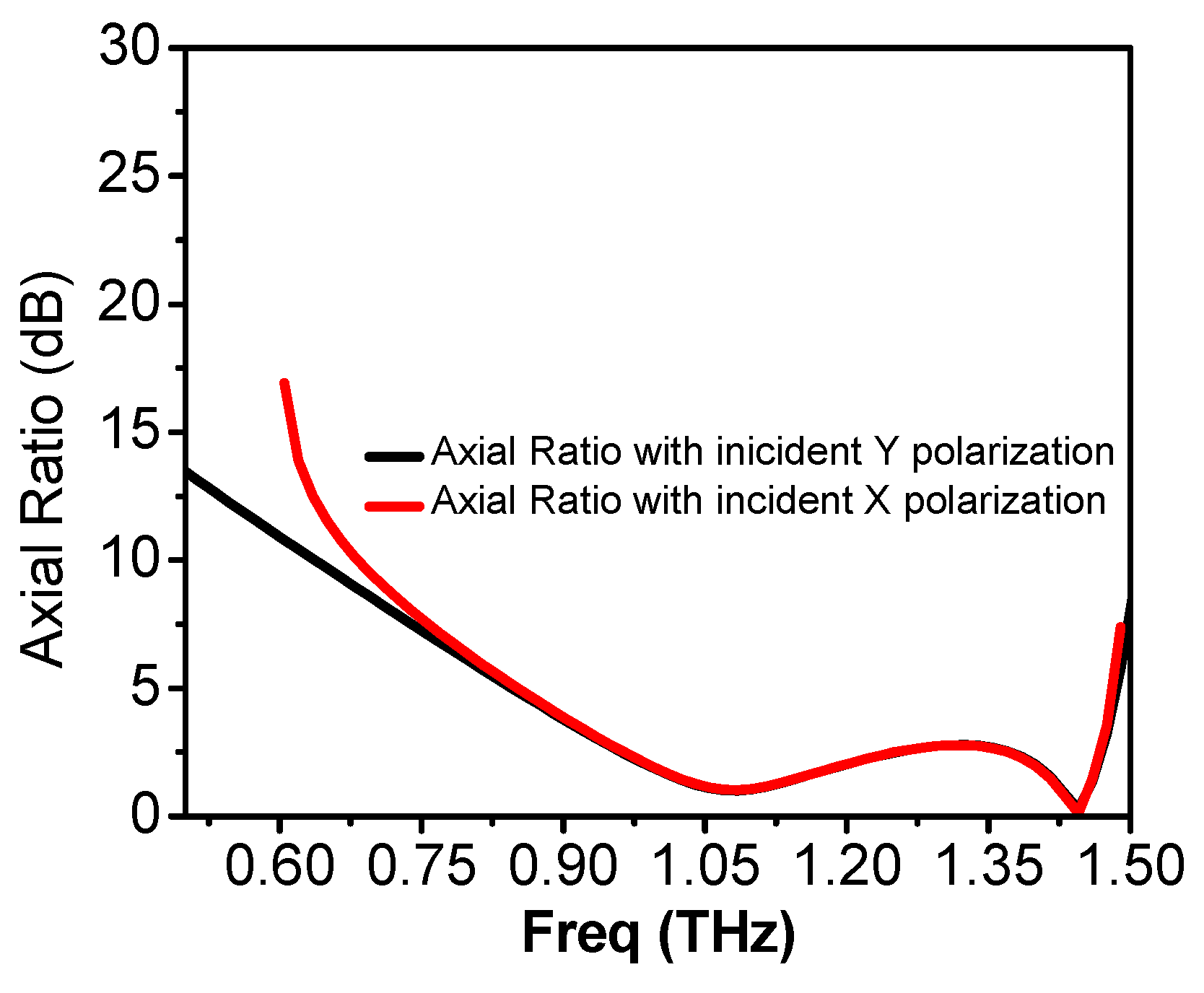
3.3. Performance Analysis of the LCPC

We analyzed the effect of different geometrical parameters of the unit cell on the performance of the polarization converter.
Figure 10a shows the plot of the axial ratio of the LCPC for different values of l while keeping all the other parameters constant. It is observed that with the increase in ‘l’ from 47.3 to 48.5 µm, the lower end of the frequency band shifts towards the left, while the higher-end remains almost stable, except for ‘l’ = 48 µm. As ‘l’ increases, the width of the outer square ring decreases, changing the resonance frequency of the outer square, hence increasing the bandwidth of the proposed converter. However, after the optimized value, further increase in l degrades the performance of the polarization converter as the axial ratio increases beyond 3 dB within the band. Figure 10b shows the influence of ‘c’ on the performance of the converter. ‘c’ affects the center patch in many ways as it varies the dimensions of the three squares being eliminated from the ‘b × b’ patch. Also, it influences many parameters in the equivalent electric circuit (C1, C2, C5, L2, and L3). It can be observed that as ‘c’ increases from 11.5 µm to 13.5 µm, the frequency band shifts towards the right, except at ‘c’ = 12 µm, which is the optimized value for our proposed structure. It can be seen from Figure 8b that the ‘c × c’ patch confines the highest electromagnetic energy between the two consecutive corners of the ‘c × c’ patch. This gap between the two corners cannot be too narrow nor too wide to allow a confined electromagnetic field which will ultimately affect the coupling between the top and ground surfaces and will influence the bandwidth of operation along with a slight shift in the frequency band.
Figure 10c shows the effect of ‘a’ on the performance of the proposed converter. We varied ‘a’ from 48 µm to 50.5 µm while keeping all other parameters constant. Increasing ‘a’ has a similar effect as what was observed with ‘l’ as it also affects the width of the outer square ring, which influences the frequency of operation and hence varies the operating bandwidth. However, the tendency of change in the bandwidth varies as at a = 48 µm, the axial ratio goes beyond 3 dB, hence the transmitted wave is not a circularly polarized wave. At a = 49 µm and 51 µm, the response is almost the same, whereas the optimum response was obtained at a = 50 µm.
Next, we observed the effect of the thickness of the substrate ‘d’ on the performance. Figure 10d shows the influence of ‘d’ on the axial ratio, which shows that when ‘d’ is varied from 3.3 µm to 7.3 µm, the axial ratio of the transmitted wave varies, while keeping bandwidth of operation almost constant. It can be explained quantitatively as follows: the incident electric field on the top metasurface can be divided into two parts; one part reflecting back to the air and the other part transmitting inside the substrate. Here, we assume that conductor thickness is negligible. The transmitted wave travels inside the substrate and upon striking the substrate to ground interface, it is partially reflected back to the substrate, whereas the rest of the portion is transmitted into the air. The portion of the electromagnetic wave which was reflected back to the substrate travels back to the top surface to the substrate interface and upon striking that interface, is again divided into two portions. One portion is reflected back to the substrate, while another portion is transmitted into the air. The reflected wave traveling inside the substrate experiences phase delays and upon striking the substrate to ground interface, some portion of this wave reflects back to the substrate, and some is transmitted into the air. These multiple transmitted waves interfere with each other constructively and destructively, producing two polarized waves, one x-polarized and the other y-polarized. These waves generate circularly polarized waves when they have comparable magnitudes and difference in phase angles around 90°. Varying substrate thickness changes the phase angles and hence affects the axial ratio for the proposed converter.

3.4. Transmit Reject Filter Design and Analysis

When an incident x-polarized or y-polarized wave strikes the proposed polarization manipulator, the transmitted wave is divided into two orthogonal components, one x polarized and the other y-polarized. These two waves, when having phases 90 degrees apart, give rise to circularly polarized waves. This concept was used to design a filter. Instead of x or y polarized waves, a slant (xy-polarized) wave was applied to the designed metasurface-based structure. It was observed that the waves passed through the structure at a resonance frequency within a certain bandwidth (decided by the conductor patch layout of the unit cell). It was confirmed that the same structure behaves as a bandpass filter, allowing 0.713 THz to 1.4346 THz waves to pass through, while rejecting other frequencies lying outside the band. This structure works over 67% fractional bandwidth and gives a sharp transmission zero at 1.505 THz (rejection > 30 dB). The loss at the receive frequency is as low as 0.3 dB. Since the rejection dip is at a higher frequency than the operating band, it can be used as a transmit reject filter in receivers to reject any spurious signal in the transmission frequency of the THz communication system. Figure 11 shows the transmission characteristics of the filter.
To obtain physical insight into the transmission behavior of the proposed polarization manipulator, we considered electric field distribution for the filter within the passband. Figure 12 shows that electric field at 0.91 THz is concentrated at the outer layer of the inner patch.

3.5. Comparison with Previous Works

Table 1 compares the major characteristics of the proposed polarization converter with other state-of-the-art works. Compared with other linear to circular polarization converters [51,52,53,54,55,56,57,58], the proposed converter works for 43.9% relative bandwidth. Compared with other multifunctional polarization manipulators [27,69,70,71], the proposed design works over a wider frequency range.

4. Conclusions

In summary, a simple transmissive metasurface-based THz polarization manipulator with dual function is proposed. For incident linear x or y polarized waves, it transmits circularly polarized waves and works over 43.9% of bandwidth, which is the widest reported so far using any bilayered structure. For incident slant (xy) polarizations, it behaves as a THz wideband transmit reject filter. Close agreement between HFSS (FEM) and CST (FDTD) results ensures the validity and reliability of our design. Physical mechanisms, electrical circuit representation, and quantitative explanation of the working principle behind the polarization manipulation justify the designed structure. Such a simple and wideband polarization manipulator can be used in potential applications in THz manipulating devices, including biosensors and communication systems.

Author Contributions

Writing-Original Draft Preparation, A.K.F., Writing-Review and editing, A.K.F., C.R. and K.C., methodology, A.K.F., software, A.K.F., validation, K.C., and C.R., supervision, C.R., project administration, C.R.

Funding

This research was funded by the National Natural Science Foundation of China, grant number 61831001, the High-Level Talent Introduction Project of Beihang University, grant number ZG216S1878, and the Youth-Top-Talent Support Project of Beihang University, grant number ZG226S1821.

Conflicts of Interest

The authors declare no conflict of interest.

References

  1. Seifert, T.; Jaiswal, S.; Martens, U.; Hannegan, J.; Braun, L.; Maldonado, P.; Beaurepaire, E. Efficient metallic spintronic emitters of ultrabroadband terahertz radiation. Nat. Photonics 2016, 10, 483. [Google Scholar] [CrossRef]
  2. Zangeneh-Nejad, F.; Safian, R. Significant enhancement in the efficiency of photoconductive antennas using a hybrid graphene molybdenum disulphide structure. J. Nanophotonics 2016, 10, 036005. [Google Scholar] [CrossRef]
  3. Yang, S.H.; Hashemi, M.R.; Berry, C.W.; Jarrahi, M. 7.5% opticalto-terahertz conversion efficiency offered by photoconductive emitters with three-dimensional plasmonic contact electrodes. IEEE Trans. THz Sci. Technol. 2014, 4, 575–581. [Google Scholar] [CrossRef]
  4. Li, R.; Ruan, C.; Fahad, A.K.; Zhang, C.; Li, S. Broadband and high-power terahertz radiation source based on extended interaction klystron. Sci. Rep. 2019, 9, 4584. [Google Scholar] [CrossRef] [PubMed]
  5. Markelz, A.G.; Roitberg, A.; Heilweil, E.J. Pulsed terahertz spectroscopy of DNA, bovine serum albumin and collagen between 0.1 and 2.0 THz. Chem. Phys. Lett. 2000, 320, 42–48. [Google Scholar] [CrossRef]
  6. Katletz, S.; Pfleger, M.; Pühringer, H.; Mikulics, M.; Vieweg, N.; Peters, O.; Scherger, B.; Scheller, M.; Koch, M.; Wiesauer, K. Polarization sensitive terahertz imaging: Detection of birefringence and optical axis. Opt. Express 2012, 20, 23025–23035. [Google Scholar] [CrossRef] [PubMed]
  7. Zangeneh-Nejad, F.; Safian, R. Hybrid graphene–molybdenum disulphide based ring resonator for label-free sensing. Opt. Commun. 2016, 371, 9–14. [Google Scholar] [CrossRef]
  8. Brown, E.R. Fundamentals of terrestrial millimeter-wave and THz remote sensing. Int. J. High Speed Electron. Syst. 2003, 13, 995–1097. [Google Scholar] [CrossRef]
  9. Liu, Y.; Zhang, X. Metamaterials: A new frontier of science and technology. Chem. Soc. Rev. 2011, 40, 2494–2507. [Google Scholar] [CrossRef]
  10. Meinzer, N.; Barnes, W.L.; Hooper, I.R. Plasmonic meta-atoms and metasurfaces. Nat. Photonics 2014, 8, 889. [Google Scholar] [CrossRef]
  11. Tonouchi, M. Cutting-edge terahertz technology. Nat. Photonics 2007, 1, 97. [Google Scholar] [CrossRef]
  12. Jepsen, P.U.; Cooke, D.G.; Koch, M. Terahertz spectroscopy and imaging–Modern techniques and applications. Laser Photonics Rev. 2011, 5, 124–166. [Google Scholar] [CrossRef]
  13. Nagatsuma, T.; Ducournau, G.; Renaud, C.C. Advances in terahertz communications accelerated by photonics. Nat. Photonics 2016, 10, 371. [Google Scholar] [CrossRef]
  14. Aldhubaib, F.; Shuley, N.V. Radar target recognition based on modified characteristic polarization states. IEEE Trans. Aerosp. Electron. Syst. 2010, 46, 1921–1933. [Google Scholar] [CrossRef]
  15. Jia, Y.; Liu, Y.; Guo, Y.J.; Li, K.; Gong, S.X. Broadband polarization rotation reflective surfaces and their applications to RCS reduction. IEEE Trans. Antennas Propag. 2015, 64, 179–188. [Google Scholar] [CrossRef]
  16. Hadad, Y.; Sounas, D.L.; Alu, A. Space-time gradient metasurfaces. Phys. Rev. B 2015, 92, 100304. [Google Scholar] [CrossRef]
  17. Taravati, S.; Kishk, A.A. Advanced wave engineering via obliquely illuminated space-time-modulated slab. IEEE Trans. Antennas Propag. 2018, 67, 270–281. [Google Scholar] [CrossRef]
  18. Taravati, S.; Kishk, A.A. Dynamic modulation yields one-way beam splitting. Phys. Rev. B 2019, 99, 075101. [Google Scholar] [CrossRef] [Green Version]
  19. Shi, Y.; Han, S.; Fan, S. Optical circulation and isolation based on indirect photonic transitions of guided resonance modes. ACS Photonics 2017, 4, 1639–1645. [Google Scholar] [CrossRef]
  20. Zang, J.W.; Correas-Serrano, D.; Do, J.T.S.; Liu, X.; Alvarez-Melcon, A.; Gomez-Diaz, J.S. Nonreciprocal wavefront engineering with time-modulated gradient metasurfaces. Phys. Rev. Appl. 2019, 11, 054054. [Google Scholar] [CrossRef]
  21. Kaveev, A.K.; Kropotov, G.I.; Tsypishka, D.I.; Tzibizov, I.A.; Vinerov, I.A.; Kaveeva, E.G. Tunable wavelength terahertz polarization converter based on quartz waveplates. Appl. Opt. 2014, 53, 5410–5415. [Google Scholar] [CrossRef]
  22. Masson, J.B.; Gallot, G. Terahertz achromatic quarter-wave plate. Opt. Lett. 2006, 31, 265–267. [Google Scholar] [CrossRef] [Green Version]
  23. Hsieh, C.F.; Pan, R.P.; Tang, T.T.; Chen, H.L.; Pan, C.L. Voltage-controlled liquid-crystal terahertz phase shifter and quarter-wave plate. Opt. Lett. 2006, 31, 1112–1114. [Google Scholar] [CrossRef] [Green Version]
  24. Zi, J.; Xu, Q.; Wang, Q.; Tian, C.; Li, Y.; Zhang, X.; Zhang, W. Terahertz polarization converter based on all-dielectric high birefringence metamaterial with elliptical air holes. Opt. Commun. 2018, 416, 130–136. [Google Scholar] [CrossRef] [Green Version]
  25. Strikwerda, A.C.; Fan, K.; Tao, H.; Pilon, D.V.; Zhang, X.; Averitt, R.D. Comparison of birefringent electric split-ring resonator and meanderline structures as quarter-wave plates at terahertz frequencies. Opt. Express 2009, 17, 136–149. [Google Scholar] [CrossRef]
  26. Weis, P.; Paul, O.; Imhof, C.; Beigang, R.; Rahm, M. Strongly birefringent metamaterials as negative index terahertz wave plates. Appl. Phys. Lett. 2009, 95, 171104. [Google Scholar] [CrossRef]
  27. Peng, L.; Li, X.F.; Jiang, X.; Li, S.M. A novel THz half-wave polarization converter for cross-polarization conversions of both linear and circular polarizations and polarization conversion ratio regulating by graphene. J. Lightwave Technol. 2018, 36, 4250–4258. [Google Scholar] [CrossRef]
  28. Lin, X.W.; Wu, J.B.; Hu, W.; Zheng, Z.G.; Wu, Z.J.; Zhu, G.; Lu, Y.Q. Self-polarizing terahertz liquid crystal phase shifter. AIP Adv. 2011, 1, 032133. [Google Scholar] [CrossRef]
  29. Hsieh, C.F.; Lai, Y.C.; Pan, R.P.; Pan, C.L. Polarizing terahertz waves with nematic liquid crystals. Opt. Lett. 2008, 33, 1174–1176. [Google Scholar] [CrossRef]
  30. Wang, L.; Ge, S.; Hu, W.; Nakajima, M.; Lu, Y. Tunable reflective liquid crystal terahertz waveplates. Opt. Mater. Express 2017, 7, 2023–2029. [Google Scholar] [CrossRef]
  31. Reid, M.; Fedosejevs, R. Terahertz birefringence and attenuation properties of wood and paper. Appl. Opt. 2006, 45, 2766–2772. [Google Scholar] [CrossRef] [Green Version]
  32. Scherger, B.; Scheller, M.; Vieweg, N.; Cundiff, S.T.; Koch, M. Paper terahertz wave plates. Opt. Express 2011, 19, 24884–24889. [Google Scholar] [CrossRef]
  33. Huang, Y.; Yao, Z.; Hu, F.; Liu, C.; Yu, L.; Jin, Y.; Xu, X. Tunable circular polarization conversion and asymmetric transmission of planar chiral graphene-metamaterial in terahertz region. Carbon 2017, 119, 305–313. [Google Scholar] [CrossRef]
  34. Kanda, N.; Konishi, K.; Kuwata-Gonokami, M. Terahertz wave polarization rotation with double layered metal grating of complimentary chiral patterns. Opt. Express 2007, 15, 11117–11125. [Google Scholar] [CrossRef]
  35. Kenanakis, G.; Zhao, R.; Stavrinidis, A.; Konstantinidis, G.; Katsarakis, N.; Kafesaki, M.; Economou, E.N. Flexible chiral metamaterials in the terahertz regime: A comparative study of various designs. Opt. Mater. Express 2012, 2, 1702–1712. [Google Scholar] [CrossRef]
  36. Wu, P.C.; Zhu, W.; Shen, Z.X.; Chong, P.H.J.; Ser, W.; Tsai, D.P.; Liu, A.Q. Broadband Wide-Angle Multifunctional Polarization Converter via Liquid-Metal-Based Metasurface. Adv. Opt. Mater. 2017, 5, 1600938. [Google Scholar] [CrossRef]
  37. Yan, L.; Zhu, W.; Karim, M.F.; Cai, H.; Gu, A.Y.; Shen, Z.; Liu, A.Q. Arbitrary and Independent Polarization Control in Situ via a Single Metasurface. Adv. Opt. Mater. 2018, 6, 1800728. [Google Scholar] [CrossRef]
  38. Chen, W.T.; Török, P.; Foreman, M.R.; Liao, C.Y.; Tsai, W.Y.; Wu, P.R.; Tsai, D.P. Integrated plasmonic metasurfaces for spectropolarimetry. Nanotechnology 2016, 27, 224002. [Google Scholar] [CrossRef] [Green Version]
  39. Jiang, Y.; Wang, L.; Wang, J.; Akwuruoha, C.N.; Cao, W. Ultra-wideband high-efficiency reflective linear-to-circular polarization converter based on metasurface at terahertz frequencies. Opt. Express 2017, 25, 27616–27623. [Google Scholar] [CrossRef]
  40. Lin, B.Q.; Guo, J.; Wang, Y.; Wang, Z.; Huang, B.; Liu, X. A Wide-Angle and Wide-Band Circular Polarizer Using a Bi-Layer Metasurface. Prog. Electromag. Res. 2018, 161, 125–133. [Google Scholar] [CrossRef]
  41. Zang, X.F.; Liu, S.J.; Gong, H.H.; Wang, Y.; Zhu, Y.M. Dual-band superposition induced broadband terahertz linear-to-circular polarization converter. JOSA B 2018, 35, 950–957. [Google Scholar] [CrossRef]
  42. Gao, X.; Han, X.; Cao, W.P.; Li, H.O.; Ma, H.F.; Cui, T.J. Ultrawideband and high-efficiency linear polarization converter based on double V-shaped metasurface. IEEE Trans. Antennas Propag. 2015, 63, 3522–3530. [Google Scholar] [CrossRef]
  43. Ji-Bao, Y.; Hua, M.; Jia-Fu, W.; Ming-De, F.; Yong-Feng, L.; Shao-Bo, Q. High-efficiency ultra-wideband polarization conversion metasurfaces based on split elliptical ring resonators. Acta Phys. Sin. 2015, 64, 178101–178105. [Google Scholar] [CrossRef]
  44. Yu, X.; Gao, X.; Qiao, W.; Wen, L.; Yang, W. Broadband tunable polarization converter realized by graphene-based metamaterial. IEEE Photonics Technol. Lett. 2016, 28, 2399–2402. [Google Scholar] [CrossRef]
  45. Chen, M.; Chang, L.; Gao, X.; Chen, H.; Wang, C.; Xiao, X.; Zhao, D. Wideband tunable cross polarization converter based on a graphene metasurface with a hollow-carved H array. IEEE Photonics J. 2017, 9, 1–11. [Google Scholar] [CrossRef]
  46. Zeng, L.; Huang, T.; Liu, G.B.; Zhang, H.F. A tunable ultra-broadband linear-to-circular polarization converter containing the graphene. Opt. Commun. 2019, 436, 7–13. [Google Scholar] [CrossRef]
  47. Jiang, Y.; Zhao, H.; Wang, L.; Wang, J.; Cao, W.; Wang, Y. Broadband linear-to-circular polarization converter based on phosphorene metamaterial. Opt. Mater. Express 2019, 9, 2088–2097. [Google Scholar] [CrossRef]
  48. Zhang, L.; Mei, S.; Huang, K.; Qiu, C.W. Advances in full control of electromagnetic waves with metasurfaces. Adv. Opt. Mater. 2016, 4, 818–833. [Google Scholar] [CrossRef]
  49. Baena, J.D.; Glybovski, S.B.; del Risco, J.P.; Slobozhanyuk, A.P.; Belov, P.A. Broadband and thin linear-to-circular polarizers based on self-complementary zigzag metasurfaces. IEEE Trans. Antennas Propag. 2017, 65, 4124–4133. [Google Scholar] [CrossRef]
  50. Liu, Y.; Luo, Y.; Liu, C.; Song, K.; Zhao, X. Linear polarization to left/right-handed circular polarization conversion using ultrathin planar chiral metamaterials. Appl. Phys. A 2017, 123, 571. [Google Scholar] [CrossRef]
  51. Zhu, H.L.; Cheung, S.W.; Chung, K.L.; Yuk, T.I. Linear-to-circular polarization conversion using metasurface. IEEE Trans. Antennas Propag. 2013, 61, 4615–4623. [Google Scholar] [CrossRef]
  52. Akgol, O.; Altintas, O.; Unal, E.; Karaaslan, M.; Karadag, F. Linear to left-and right-hand circular polarization conversion by using a metasurface structure. Int. J. Microw. Wirel. Technol. 2018, 10, 133–138. [Google Scholar] [CrossRef]
  53. Akgol, O.; Unal, E.; Altintas, O.; Karaaslan, M.; Karadag, F.; Sabah, C. Design of metasurface polarization converter from linearly polarized signal to circularly polarized signal. Optik 2018, 161, 12–19. [Google Scholar] [CrossRef]
  54. Altintas, O.; Unal, E.; Akgol, O.; Karaaslan, M.; Karadag, F.; Sabah, C. Design of a wide band metasurface as a linear to circular polarization converter. Mod. Phys. Lett. B 2017, 31, 1750274. [Google Scholar] [CrossRef]
  55. Abadi, S.M.A.M.H.; Behdad, N. Wideband linear-to-circular polarization converters based on miniaturized-element frequency selective surfaces. IEEE Trans. Antennas Propag. 2015, 64, 525–534. [Google Scholar] [CrossRef]
  56. Lin, B.Q.; Guo, J.X.; Huang, B.G.; Fang, L.B.; Chu, P.; Liu, X.W. Wideband linear-to-circular polarization conversion realized by a transmissive anisotropic metasurface. Chin. Phys. B 2018, 27, 054204. [Google Scholar] [CrossRef]
  57. Perez-Palomino, G.; Page, J.E.; Arrebola, M.; Encinar, J.A. A design technique based on equivalent circuit and coupler theory for broadband linear to circular polarization converters in reflection or transmission mode. IEEE Trans. Antennas Propag. 2018, 66, 2428–2438. [Google Scholar] [CrossRef]
  58. Lin, B.; Guo, J.; Ma, Y.; Wu, W.; Duan, X.; Wang, Z.; Li, Y. Design of a wideband transmissive linear-to-circular polarization converter based on a metasurface. Appl. Phys. A 2018, 124, 715. [Google Scholar] [CrossRef]
  59. Suen, J.Y.; Fang, M.T.; Denny, S.P.; Lubin, P.M. Modeling of terabit geostationary terahertz satellite links from globally dry locations. IEEE Trans. Terahertz Sci. Technol. 2015, 5, 299–313. [Google Scholar] [CrossRef]
  60. Hansen, V.; Gemuend, H.P.; Kreysa, E. Resonant mesh filters using densely packed FSS elements for space applications. In Proceedings of the 2005 Joint 30th International Conference on Infrared and Millimeter Waves and 13th International Conference on Terahertz Electronics, Williamsburg, VA, USA, 19–23 September 2005. pp. 209–210.
  61. Chowdhury, D.R.; Singh, R.; Reiten, M.; Chen, H.T.; Taylor, A.J.; O’Hara, J.F.; Azad, A.K. A broadband planar terahertz metamaterial with nested structure. Opt. Express 2011, 19, 15817–15823. [Google Scholar] [CrossRef] [PubMed]
  62. Yeh, T.T.; Genovesi, S.; Monorchio, A.; Prati, E.; Costa, F.; Huang, T.Y.; Yen, T.J. Ultra-broad and sharp-transition bandpass terahertz filters by hybridizing multiple resonances mode in monolithic metamaterials. Opt. Express 2012, 20, 7580–7589. [Google Scholar] [CrossRef] [PubMed]
  63. Han, J.; Gu, J.; Lu, X.; He, M.; Xing, Q.; Zhang, W. Broadband resonant terahertz transmission in a composite metal-dielectric structure. Opt. Express 2009, 17, 16527–16534. [Google Scholar] [CrossRef] [PubMed] [Green Version]
  64. Chiang, Y.J.; Yang, C.S.; Yang, Y.H.; Pan, C.L.; Yen, T.J. An ultrabroad terahertz bandpass filter based on multiple-resonance excitation of a composite metamaterial. Appl. Phys. Lett. 2011, 99, 191909. [Google Scholar] [CrossRef] [Green Version]
  65. Hunter, I.; Guyette, A.; Pollard, R.D. Passive microwave receive filter networks using low-Q resonators. IEEE Microw. Mag. 2005, 6, 46–53. [Google Scholar] [CrossRef]
  66. Li, Y.; Zhang, J.; Qu, S.; Wang, J.; Zheng, L.; Pang, Y.; Zhang, A. Achieving wide-band linear-to-circular polarization conversion using ultra-thin bi-layered metasurfaces. J. Appl. Phys. 2015, 117, 044501. [Google Scholar] [CrossRef]
  67. Jawitz, M.W.; Jawitz, M.J. Materials for Rigid and Flexible Printed Wiring Boards; CRC Press: Boca Raton, FL, USA, 2018; Article 5.4.3.3. [Google Scholar]
  68. Guo, Y.; Wang, Y.; Pu, M.; Zhao, Z.; Wu, X.; Ma, X.; Luo, X. Dispersion management of anisotropic metamirror for super-octave bandwidth polarization conversion. Sci. Rep. 2015, 5, 8434. [Google Scholar] [CrossRef] [PubMed]
  69. Ma, X.; Xiao, Z.; Liu, D. Dual-band cross polarization converter in bi-layered complementary chiral metamaterial. J. Mod. Opt. 2016, 63, 937–940. [Google Scholar] [CrossRef]
  70. lKhan, M.I.; Khalid, Z.; Tahir, F.A. Linear and circular-polarization conversion in X-band using anisotropic metasurface. Sci. Rep. 2019, 9, 4552. [Google Scholar]
  71. Cheng, Z.; Cheng, Y. A multi-functional polarization convertor based on chiral metamaterial for terahertz waves. Opt. Commun. 2019, 435, 178–182. [Google Scholar] [CrossRef]
  72. Guo, T.; Argyropoulos, C. Broadband polarizers based on graphene metasurfaces. Opt. Lett. 2016, 41, 5592–5595. [Google Scholar] [CrossRef] [Green Version]
Figure 1. Schematic of the design: (a) Two-dimensional (2D) periodic array structure (b) Top view (X-Y) (c) 3D perspective view.
Electronics 08 01068 g001
Figure 2. Equivalent circuit for the proposed converter under (a) X-polarization, (b) Y-polarization.
Electronics 08 01068 g002
Figure 3. Transmission characteristics with incident (a) x-polarized (b) y-polarized waves.
Electronics 08 01068 g003
Figure 4. The phase difference between x-polarized and y-polarized transmitted waves with incident x-polarized wave.
Electronics 08 01068 g004
Figure 5. Axial ratio for the transmitted wave.
Electronics 08 01068 g005
Figure 6. Ellipticity for the transmitted wave with incident x polarized wave.
Electronics 08 01068 g006
Figure 7. Surface current distributions at 1.085 THz: (a) top surface; (b) ground surface; and at 1.454 THz: (c) top surface; (d) ground surface.
Electronics 08 01068 g007
Figure 8. Electric field distribution considering the four cells of the metasurface array at: (a) 1.085 THz; (b) 1.454 THz.
Electronics 08 01068 g008
Figure 9. Polarized wave trajectory at frequencies of (a) 1.085THz, (b) 1.387 THz, (c) 1.175 THz, and (d) 0.995 THz.
Electronics 08 01068 g009
Figure 10. Effect of (a) ‘l’, (b) ‘c’, (c) ‘a’, and (d) ‘d’ on the performance of the LCPC.
Electronics 08 01068 g010
Figure 11. Transmission characteristics of the receive filter.
Electronics 08 01068 g011
Figure 12. Electric field distribution with incident slant (xy) polarization at 0.91 THz frequency.
Electronics 08 01068 g012
Table 1. Comparisons of the proposed polarization manipulator with other polarization converters/multifunctional devices.
ReferenceFunctionRelative BandwidthNo. of LayersThickness
[51]Linear (x or y) to CP 6%10.0063 λc
[52]Linear (x or y) to CP14.45%10.022 λc
[53]Linear (x or y) to CP6.510.016 λc
[54]Linear (x or y) to CP12%10.009 λc
[55]Linear (x and y) to CP40%60.18λc
[56]Linear (x or y) to CP40.430.21 λc
[57]Linear (x and y) to CP40%30.5 λc
[58]Linear (x and y) to CP40.2%30.143 λc
[70]Linear to dual band CP and linear to cross2.6%, 3.4%, 31.6%20.053 λc
[71]Y to LHCP, x to RHCP, x to y@ single frequency (1.14 THz,1.34 THz), 12%20.03 λc
[27]Linear to cross linear, circular to cross circular32%30.09 λc
[72]Linear (x and y) to CP, linear to elliptical@ 4.75 THz, and 16.3%10.025 λc
This WorkX to LHCP, y to RHCP, slant (xy) to transmit reject filter43.9%, 43.9%, 67%20.02 λc

