1. Introduction
Access points (APs) are being increasingly deployed in wireless local area networks (WLANs) as a means of fulfilling cellular system offload requirements [
1]. Since the service area covered by an AP in a WLAN system is considered to be a
small cell, many APs must be deployed in areas with heavy traffic. However, since individual APs have limited frequency channels, collisions will occur between user terminals (UTs) when many UTs attempt to connect with an AP. To avoid such collisions, wired LAN systems can implement an access control scheme called carrier sense multiple access/collision detection (CSMA/CD) in which, prior to packet transmission, collisions are detected from voltage variations occurring within the Ethernet cable [
2]. As this method for wired LAN transmission involves packet detection in advance and immediate retransmission, its efficiency is over 90% [
3]. As a result, the issues surrounding this method have been intensively studied [
4,
5].
On the other hand, another access control scheme called CSMA/collision avoidance (CA) is adopted in wireless LAN [
6]. Unlike wired LAN, it is difficult to detect the packet collision with wireless transmission. Therefore, the reception characteristics are judged from the reply of acknowledgement (ACK) sent by a receiving station. Compared to wired LAN, the transmission efficiency of wireless LAN is very small, and its value is less than 65%, because retransmission cannot be started until ACK is judged [
3]. Therefore, collision detection, which is used in wired communication systems, is essential for achieving high transmission efficiency.
There are two types of collision detection schemes. The first collision detection method involves single-user MIMO transmission [
7,
8]. For 2 × 2 MIMO, this method utilizes the fact that the second antenna is idle when the first antenna transmit short preamble signals, which are used for timing synchronization with the UT. The
self-interference between these two antennas at the AP can be canceled by using dual polarized antennas, which are generally used in MIMO systems [
9,
10,
11]. In this paper, this idea is applied for multi-user MIMO systems.
In the second method, an approximate CSMA/CD for WLANs is realized using a scheme called CSMA/collision notification (CN) [
12]. In CSMA/CN, a receiver detects the interfering signal while receiving a packet and immediately notifies the transmitter, which utilizes two antennas: one for normal transmission and the other dedicated to listening for notifications. Upon detection of a notification signal, the transmitter aborts its transmission, freeing up the channel for other transmitters in the vicinity [
12].
Since the transmitter must use an additional antenna to discriminate between its own transmit signal and the notification signal from the receiver, the CSMA/CN procedure utilizes a correlation calculation based on a prior (training) signal received at the transmitter. When the notification signal arrives during the transmission of the own transmit signal, another antenna judges whether collision is detected, because the correlation value between the received signal (ideally only notification signal plus the noise) and the known training signal becomes high after canceling the own transmit signal [
12].
However, there are two issues in the CSMA/CN procedure. Firstly, it is difficult to detect collision in a real propagation environment using only the correlation value, because the correlation value with limited number of samples is actually very small as the power level of the notification signal is much lower than that of the own transmit signal at another antenna on the transmitter. Secondly, since the power of the own transmit signal is much higher than that of the notification signal from the receiver, the received power becomes saturated at the amplifier and it causes the noise power to increase; [
12] provided there is no concrete countermeasure for this effect. In addition to these problems, feedback delay may still occur even if the receiver immediately notifies the transmitter of a collision. These two problems have been improved by [
7,
8].
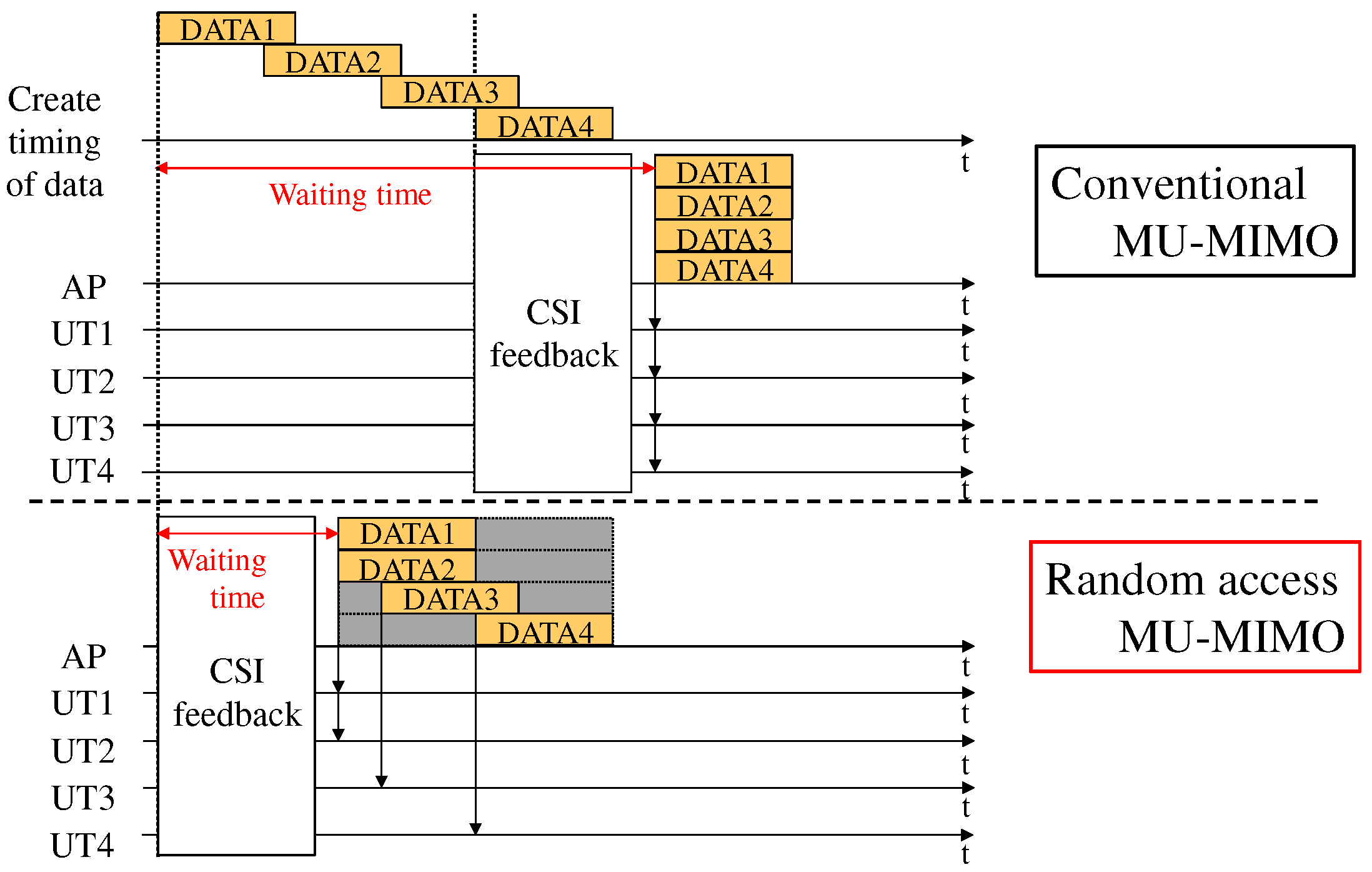
In this paper, a novel collision detection method using asynchronous MU-MIMO transmission called random access MU-MIMO [
13] is proposed. In random access MU-MIMO, the transmission from each user is started immediately after preparing the data packet for a certain user. Hence, asynchronous downlink transmission is employed, and null data is transmitted for the user whose data packet is not prepared. In this study, we utilize this feature on random access MU-MIMO, and idle antennas, which do not transmit any signal, can be prepared instead of transmitting null data. Thus, the collision detection using idle antennas in random access MU-MIMO is realized similar to that in single user MIMO. In random access MU-MIMO, the unused antennas can receive preamble signals, while transmission is employed with multiple antennas that are used in random access MU-MIMO.
The signals are mapped to several subcarriers in short preamble signals of IEEE802.11 based OFDM signals, and the signals in the frequency domain are transformed by IFFT at the transmitter. At the receiver, the correlation is calculated, and the initial timing of short preamble signals is detected. Conventionally, the short preamble signals are discarded after timing synchronization. On the other hand, in the proposed method, the short preamble signals are transformed into the frequency domain by FFT processing. The interference from the interfering user terminals (IT) can be detected by subtracting the short preamble signal, which is multiplied by the estimated channel response using the received signal. The effectiveness of the proposed method is shown by computer simulation. In addition, the interfering power from the IT at the AP and desired user terminal (DT) is verified by assuming packet collision in an actual indoor environment. By analyzing the interfering signal power from IT to AP and DT, the possibility of collision detection using the proposed method is demonstrated.
The remainder of this paper is organized as follows.
Section 2 shows the proposed method using random access MU-MIMO. The basic characteristics and effectiveness of the proposed method are demonstrated via computer simulation in
Section 3. In order to verify the possibility of using the proposed method at the AP, the characteristics of the interference power in an actual indoor environment is presented in
Section 4.
3. Effectiveness of the Proposed Method by Computer Simulation
Through this computer simulation, in which IEEE802.11n/ac-based OFDM signal is assumed, the effectiveness of the proposed method is verified by evaluating the characteristics of self-interference reduction and detection of interference from ITs.
Table 1 shows the simulation parameters. As can be seen in
Table 1, when considering the self-interference signal between AP antennas, the average signal to noise power ratio (average SNR) is set to be 45 dB from the previous measurement [
7], and we confirmed that the fading caused by self-interference between AP antennas can be negligible due to its large power, even if people work around the AP [
8]. On the other hand, the propagation of interference signal is assumed to be Rayleigh fading. In the simulation, the signal to interference power ratio (SIR) is changed from 0 to 50 dB. The other basic parameters are the same as that for the IEEE802.11n/ac standard with 20 MHz mode. When
denotes the estimated channel response between the AP antennas and
denotes the time variation of channel response,
, the channel response between the
i-th transmit and a receive antenna of the AP is denoted as
From the results in [
8],
is set to be 0.9999 in the evaluation.
The simulation process is summarized as follows:
[Step (1)] The desired signal and the interference signal with the OFDM signal format are created and added.
[Step (2)] The short preamble signal is detected from the signal by the sliding correlation.
[Step (3)] The interference signal is estimated and detected.
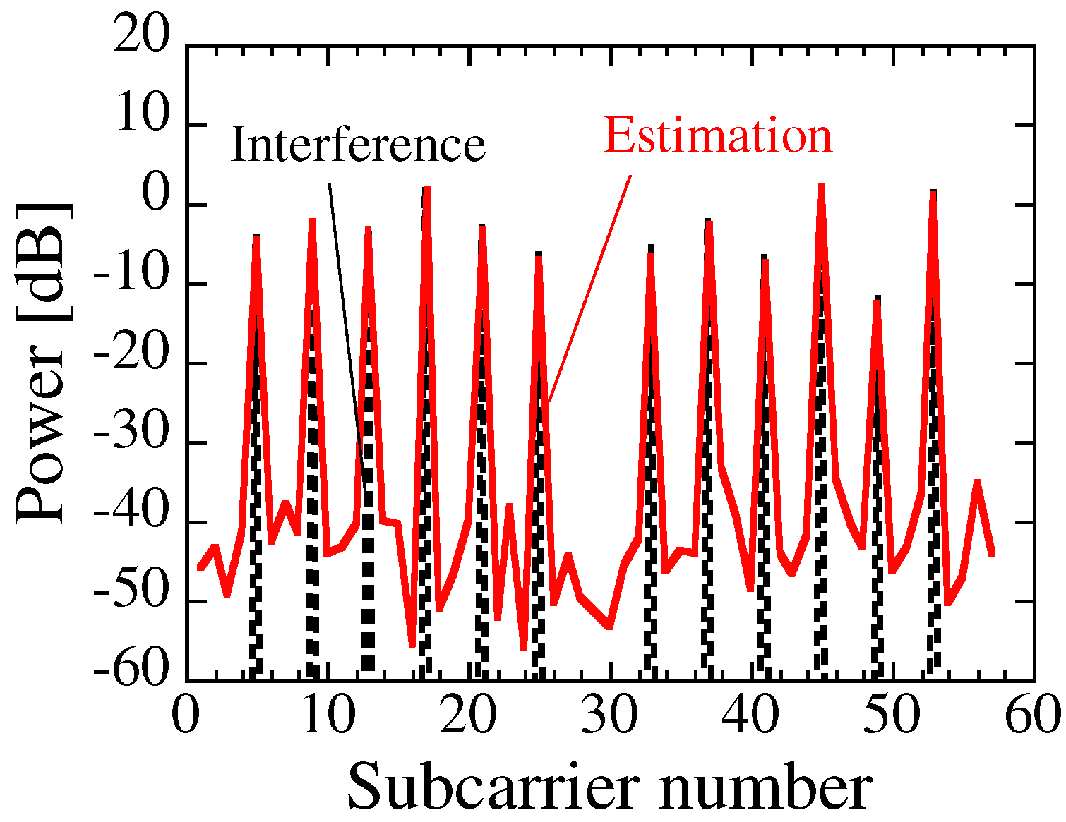
Figure 5 and
Figure 6 show the received power of interference from IT in the frequency domain, and these are estimated by the proposed method by assuming that the SIR is 10 and 45 dB. The received power is not transmitted when there is self-interference between the AP antennas; only the interference signal from the IT arrives at the receiver of the AP. The estimated and ideal interfering powers are plotted in these figures. When considering low SIR, as shown in
Figure 5, the interference power versus subcarrier number for the estimated interfering power is almost identical to that for the ideal interfering power. Although the estimation seems to be possible when the SIR is 10 dB (in
Figure 5), we can observe that the estimation error with SIR = 45 dB is much larger than that with SIR = 10 dB.
In order to evaluate how to estimate the interference signal when considering low SIR, the interference channel response is estimated by using Equations (
2) and (
4). If the multiplication of interference signal and short preamble signal is denoted as
, the estimated equation is denoted as
The estimation error on the interference power by the proposed method is evaluated. The estimation error is denoted as
where
and
denote the ideal and estimated interference power, respectively.
In this study, the number of trials was 10,001.
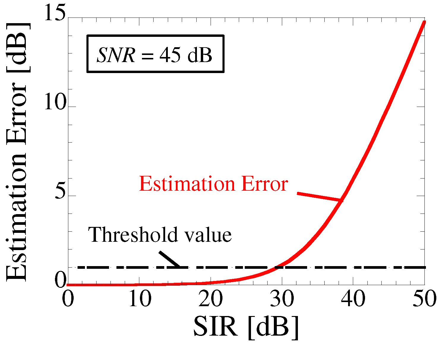
Figure 7 shows the estimation error versus SIR. The median values are plotted for each SIR for all the trials by changing the channel response. As can be seen in
Figure 7, the estimation error is less than 1 dB, when the SIR is less than 30 dB. Hence, the proposed method can successfully cancel the self-interference between AP antennas and estimate the interference with small power.
4. Interference Power Characteristics in an Actual Indoor Environment
We carried out indoor measurement using IEEE802.11n/ac-based OFDM signals, in order to verify how serious the problem of interference is for the DT, when considering the collision detection at the AP.
Figure 8 and
Table 2 show the measurement environment and parameters, respectively. In this measurement, the interfering power from IT to AP and DTs is verified by assuming packet collision in an actual indoor environment. Hence, in this measurement, IT is a transmit antenna, and AP and DT are receive antennas. The OFDM signal has been measured in an actual indoor environment. The received power was analyzed by the measured OFDM signal. The proposed method is employed by the measured received signals in
Section 2.
The size of the room is 6.2 × 7.5 m and AP and DTs are located in a corridor (outside the room). The center frequency and transmit power are 2.55 GHz and 21 dBm, respectively. The other basic measurement parameters are the same as that for the IEEE802.11ac standard signal format. The short preamble signals are obtained by sliding correlation at each measurement point. In order to avoid specific characteristics in the measurement, the transmitter is moved with an interval of 0.5 wavelengths by using a position controller, and 17 measurement points are obtained for each transmit location.
Figure 9 shows the interference to noise power ratio (INR) versus the distance from IT to AP at the AP position. The INR is obtained by averaging 17 measurement points. The broken line indicates the threshold value, which is obtained by the estimation error with 1 dB in
Figure 7, because the INR is 15 dB when SIR and SNR are 30 and 45 dB, respectively. When the INR is greater than the threshold value, the proposed method can detect the interference while cancelling the self-interference between AP antennas. Moreover,
Figure 10 shows that the INR versus distance from IT to AP is identical in this measurement. As can be seen in
Figure 10, the interference can be detected at a distance of 16 m from the AP. Since the tendency of INR among AP and DTs are similar, the AP instead of DTs can successfully estimate the interfering power from IT when considering a room with small size.
On the other hand, it is verified from
Figure 10 that DT receives the interference but AP cannot receive interference when the distance is greater than 16 m.
Figure 11 shows the SIR of DTs versus distance from IT to AP. As can be seen in
Figure 11, in such a scenario, collision cannot be detected at the AP but the received power from AP to DT is much higher than that from IT and DT. Therefore, the communication between DT and AP is not a serious problem.
5. Conclusions
In this paper, a collision detection method using asynchronous MU-MIMO called random access MU-MIMO is proposed. This method utilizes the fact that idle antennas, which do not transmit signals, can be employed to receive and detect interference when considering random access MU-MIMO. Hence, idle antennas at the AP can receive preamble signals while transmit antennas at the AP transmits the preamble signals: this procedure is regarded as full-duplex transmission, which cancels self-interference between AP antennas. The interference can be detected by subtracting the short preamble signal, which is multiplied by the estimated channel response using the received signal after the FFT processing. Through the computer simulation, in which IEEE802.11n/ac-based OFDM signal is assumed, the effectiveness of the proposed method is verified by evaluating the characteristics of self-interference reduction and detection of interference from ITs. It is verified that the estimation error on the interference power is less than 1 dB, when the SIR is less than 30 dB. Hence, the proposed method can successfully cancel the self-interference between AP antennas and estimate interference with small power. In addition, we carried out indoor measurement using IEEE802.11n/ac-based OFDM signals, in order to verify how serious the problem of interference is for the DT, when considering the collision detection at the AP. It is shown that the proposed method accurately estimates the interference power even if the interference power is small, and that collision detection at the AP is realized from the measurement.
As the basic study in the proposed method, interference detection performance is evaluated in this paper. However, to evaluate the total system performance, the bit error rate should be evaluated. As the future study, the evaluation with the BER will be studied when considering the total system performance.

 ,
, 


