Article

Towards Realizing High-Throughput, Roll-to-Roll Manufacturing of Flexible Electronic Systems

1
Department of Electrical and Computer Engineering, the University of Texas at Austin, Austin, TX 78758, USA
2
Omega Optics, Inc., 8500 Shoal Creek Blvd, Building 4, Suite 200, Austin, TX 78757, USA
*
Author to whom correspondence should be addressed.
These authors contributed equally to this work.
Electronics 2014, 3(4), 624-635; https://doi.org/10.3390/electronics3040624
Submission received: 3 September 2014 / Revised: 15 October 2014 / Accepted: 3 November 2014 / Published: 14 November 2014
(This article belongs to the Special Issue Flexible Electronics)

Abstract

:
High-rate roll-to-roll (R2R) tracker systems are utilized for large volume flexible electronic device manufacturing, and the current alignment mechanism between layers is mainly achieved by relying on passive techniques. In this paper, we present a machine vision based alignment strategy that is used to achieve precise registration for stacking multilayers. Based on this strategy, we demonstrate two-layer printing with alignment accuracy better than 100 μm in web moving direction and 200 μm in lateral direction at a web rate of 5 m/min.

1. Introduction

Over the last decade, the printed electronics industry has been undergoing a significant growth in the market. Printed electronics refers to a set of printing methods, such as screen printing, flexography, gravure, offset lithography, inkjet printing, etc., used to create electronic devices on various substrates. Among these methods, inkjet printing is an ideal solution for low cost, high speed printed electronics, due to the low material consumption, low equipment costs, and possibility for mass customization [1]. Some important application areas include RFID [2,3], solar cells [4,5], and displays [6,7], where device structures are mainly formed by stacking patterned layers, and where the critical dimension is in the tens of microns to millimeter range. The registration accuracy between layers is of great importance in determining the quality of the devices. For a tabletop printer, such as the ones printing on small area substrates, layer to layer registration is achieved via a microscopic system. The system determines the printing origin, and both the X and the Y direction offset values, with respect to previous layers. Therefore, one can precisely align two patterns with a maximum offset of the mechanical moving part accuracy, or to be more specific, the step motor accuracy.
However, the alignment strategy for a table-top printer is not applicable for a high-rate roll-to-roll system, where the registration needs to be performed while the substrate is moving at a high speed. There are several technologies that are used to realize roll-to-roll registration. For example, Krebs et al. punch a series of registration holes along the edge of the web so that the position of the web is kept relatively constant with respect to the printer head [8]. Jung et al. utilize no external setup for registration, but the mechanical system is capable of providing overlay printing registration accuracy of ±20 μm [2]. It is a practical way to make use of the precise tracking mechanism and the edge sensor to ensure minimum sideways wander of the web. However, such “passive” alignment strategies may encounter some off-registration problems if the original web has poor edge condition (e.g., edge flatness) that affects the width of the substrate. Due to the above-mentioned problems, in the actual industry environment, most ink-jet based roll-to-roll systems are only used to deposit the first layer, which does not require accurate alignment. For stacking of subsequent layers, screen printing is employed where the registration is performed when the web is stationery. This limits the final throughput of the manufacturing process.
In this research, we introduce an “active” alignment strategy using machine vision and demonstrate the entire system setup, including the software and hardware in order to realize multi-layer alignment. A feature of our method is that the active alignment is tolerant to the imperfections in the substrate condition, and does not pose demanding requirements on the web tracking system.
To better illustrate the system details, in Section 2, we first introduce the basic idea for realizing roll-to-roll registration. Based on this idea, the main system modules are determined. Next, based on the detailed system requirements, we specify the components in every module. A customized software implementation is described for synchronizing all the components for proper functioning in Section 3 Finally, multi-layer printing test is performed and the results are analyzed in Section 4.

2. System Components

2.1. Basic Idea

The Roll-to-Roll ink-jet printing system with alignment capability is a complex electro-mechanical system. In order to realize a high-speed, multi-layer printing system with good registration, an active alignment method should be considered. It should be noted that, in designing the system, the anisotropic mechanical properties of the flexible substrate also needs to be considered, since it plays an important role in achieving good alignment accuracy in a roll-to-roll process. In order to demonstrate the feasibility of our approach, and simplify the hardware, Kapton polyimide substrate is considered in our work due to its superior mechanical properties.
Alignment marks are utilized to determine the reference position, and all subsequent layer patterns are placed with respect to this reference position. Different from the table top printer used in our previous work [9,10,11], the printhead in the high-rate roll-to-roll system is stationary, which means that the alignment marks printed on first layer are not always exposed continuously to the same range of nozzles for the second layer printing due to sideways wander of the web.
A viable solution to this problem is to utilize a high speed imaging system to get the real-time alignment mark position, and adjust the printer nozzle actuation accordingly for each copy of the pattern. Additionally, the system should also be configured to provide correct timing to start the second layer printing by using a Print/Go device.
Figure 1. Schematic drawing of the main components in the roll-to-roll printing system with active alignment function. The main modules are (1) substrate moving module; (2) pattern detection module; (3) material ink-jet printing module; 4) fast curing module and (5) system control module. Modules (2) (3) and (4) form a standalone single stage system for aligned-printing, and can be configured in series to realize multi-stage continuous printing.
Electronics 03 00624 g001

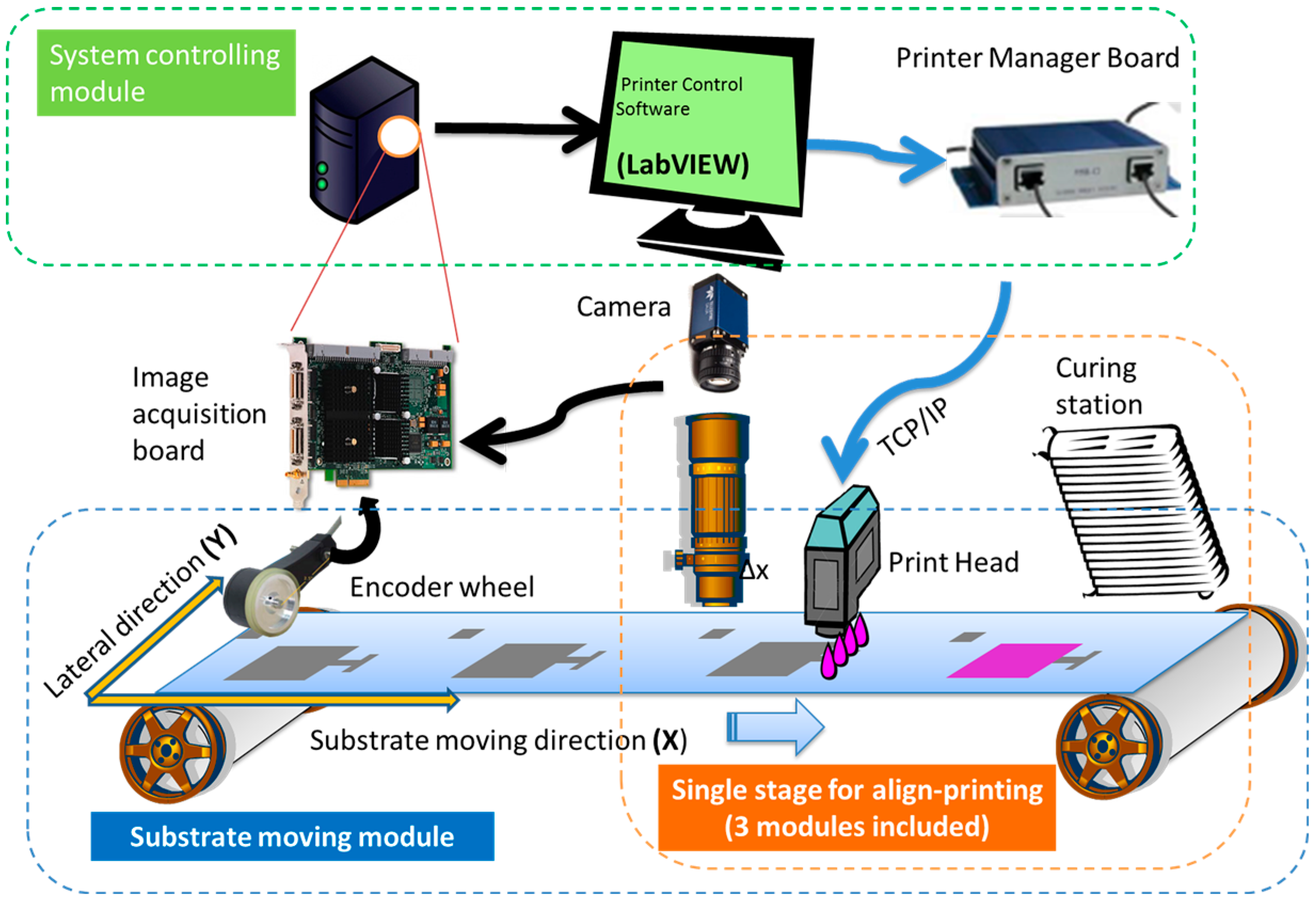
2.2. Main System Modules

Based on the above discussions, we determined the main modules for a single stage printer: pattern detection module, ink-jet printing module and fast curing module. To complete the web transfer and printing function, some other modules including substrate moving module (web tracker, encoder), system control module (desktop with the controlling software) are also needed. A cartoon briefly depicting all the components in a single stage system is shown in Figure 1.
The main functions of these modules are listed below:
  • The substrate moving module delivers the web at a controlled speed.
  • The pattern detection module captures the positions of the alignment and the Print/Go marks.
  • The ink-jet printing module retrieves and prints patterns with the desired material.
  • The curing system provides in-line fast curing of the ink.
  • The system control module processes images from the image acquisition module, and controls the ink-jet printing module.

2.3. Web Tracking Module

The tracking system contains an edge detection sensor. The sensor detects the substrate edge and controls the tilting angle of a suspending shaft so that the web edge is aligned in real time to minimize the lateral direction (Y) offset and the sideways wander of the web. Although the edge detection sensor and the actuator system can ensure rough alignment of the web edge, the sideways wander is still inevitable. Moreover, since the width variations in the web can be large (which is common for commercial substrate material rolls), edge detection by itself is not sufficient to give satisfying registration results. In the current situation, the sideways wander is observed to be around 2 mm in each direction (4 mm total).
The maximum sideway wander determines the minimum required camera field of view (FOV). Generally speaking, reducing the FOV increases the physical resolution of the captured images. However, this requires the tracker to have less sideways wander, so that all the alignment marks can be captured. Another component in the web tracking module is the TR1 wheel encoder which provides a resolution of 15 μm per pulse. The purpose of this encoder is to feedback the real time web running speed for the ink-jet printing module to make sure the printed patterns have the correct aspect ratio.

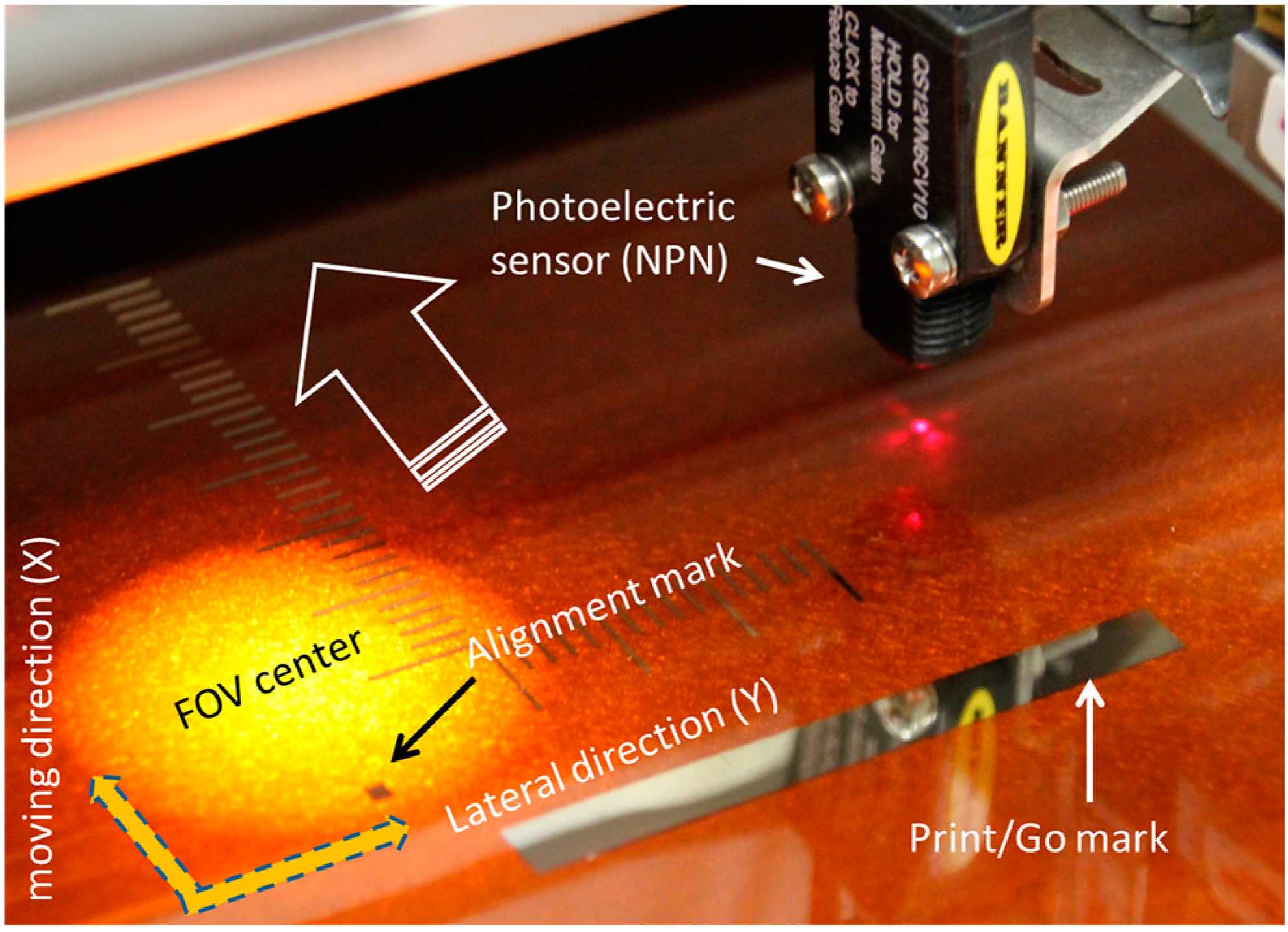
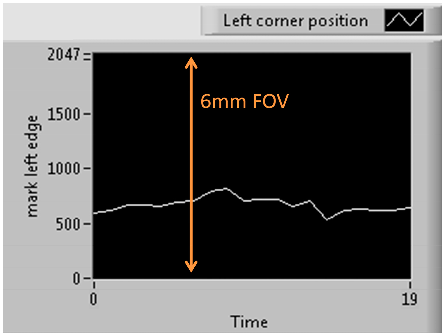
2.4. Pattern Detection Module

The purpose of the pattern detection module is to capture the alignment and the Print/Go marks on the running web. We choose a line-scan camera and an optical system with coaxial illumination to build our image acquisition setup. With a single line of pixels, line-scan sensors build continuous images not limited in their vertical resolution. Vertical resolution is dependent on the web speed.
The line-scan camera has n = 2048 pixels, and the optical zoom lens is adjusted to set the FOV to 6 mm, which yields a camera system resolution of 3 µm/pixel. The image resolution can be increased further by reducing the FOV and/or increasing the line-scan camera pixels.
The Print/Go signal is generated by a photoelectric sensor. The signal is used to trigger the actuation of the printhead. When a Print/Go mark is detected, the sensor output produces a falling edge of a TTL signal, which in turn triggers the printing. As shown in Figure 2, the alignment mark first enters the FOV for determining the Y offset. Then, the photoelectric sensor sees the Print/Go mark in order to actuate the printing.

2.5. Material Ink-Jet Printing Module

The ink-jet printhead used in the current program is a high-speed head consisting of 1024 nozzles. The actuation of the cartridge is controlled by a “Print Manager Board” (PMB), which acts as the interface between the computer and the printhead. A “Print Server” software controls the PMB. It accepts external synchronizing signals from the encoder and routes the TCP/IP commands to the printhead. It also provides options for changing the waveform settings so that the jetting speed, jetting volume, and the transfer mechanism can be specified. In our system, the jetting speed is set at 5 m/s, providing a jetting volume of 14 pL per drop.
Figure 2. Alignment mark detection using line-scan camera, and Print/Go mark detection using photoelectric sensor.
Electronics 03 00624 g002

2.6. Photonic Curing System

For the current roll-to-roll printing system, it is crucial to cure the printed ink quickly before it enters the next module. For inks and coatings containing nanoparticles, this process is called sintering. A conventional sintering process requires heating above 150 °C. However, it limits the applicable substrate, especially when the metal has a higher melting point than the flexible substrate, making it impossible to achieve sintering without causing subsequent damage to the substrate. Additionally, the curing speed of conventional systems is also relatively low for heating the ink above its melting points. To overcome these problems, a photonic curing/sintering method using high energy light pulse has been implemented.
Our photonic curing tool contains a 4.2" diameter spiral lamp (240 nm spectral cutoff). In our system, a 1.5 s exposure to 3 pulses, with a pulse energy 1500 Joules/pulse, completely sinters a printed silver nanoparticle film.

2.7. System Control Module

The system control module mainly refers to a PC equipped with the required hardware and software to perform the printing task, including acquiring images from the camera, processing the images, and sending the commands to the printhead.
The printer control is realized by TCP/IP commands. The client application initializes a command which is received by the server. The server processes the client command and starts the print engine operation. Once the operation is completed, the engine components respond to the server and the server feedbacks the client with related information. We set the printer to work in the queue print mode, thus enabling continuous addition of pre-offset images to the print queue.

3. System Integration

With the basic functions realized by each individual module, system integration is realized by applying certain algorithm for aligning multi-layers. The detailed alignment strategy is discussed in the following sub-sections, along with software implementation using National Instruments NI 2011 LabVIEW software.

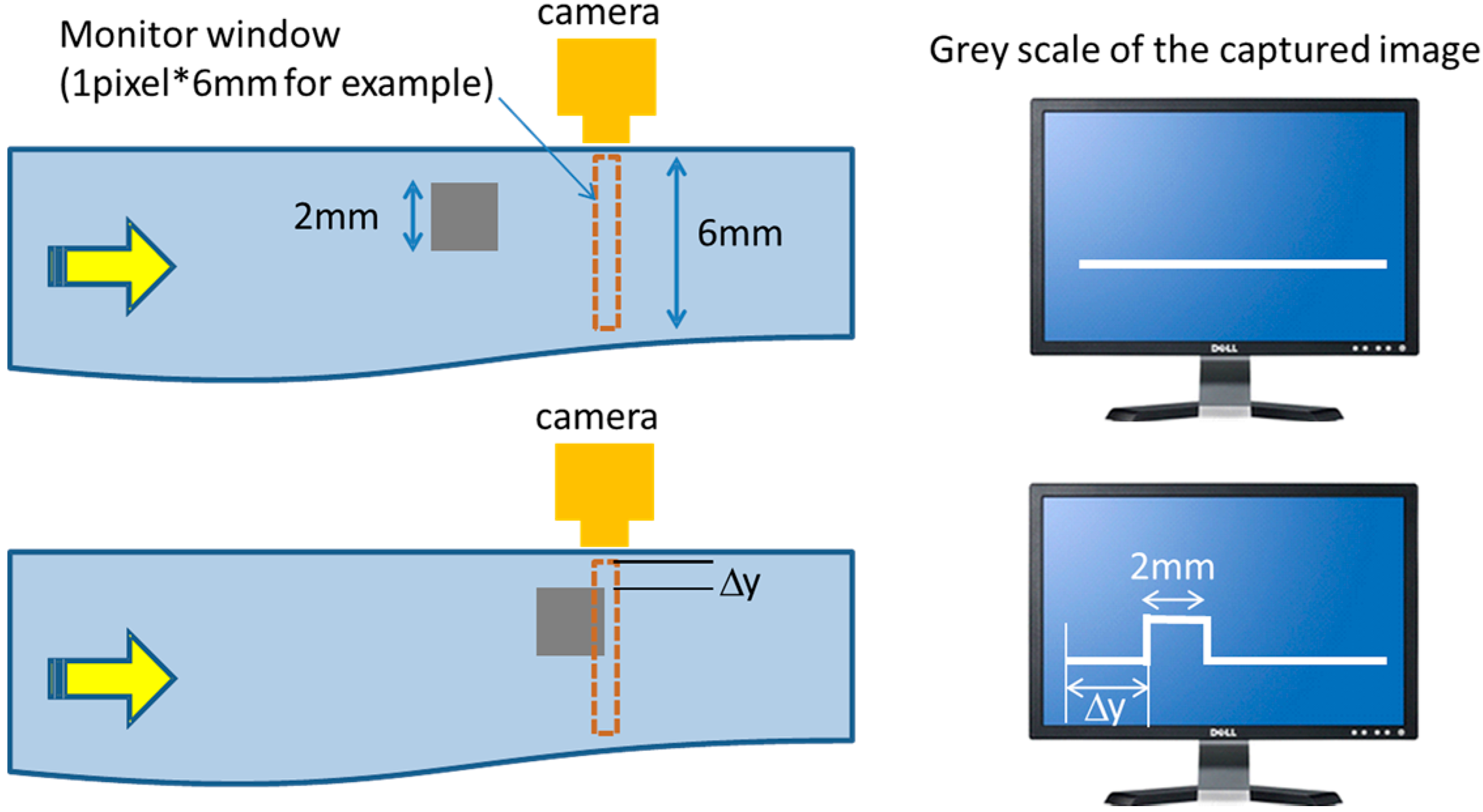
3.1. Alignment Strategy in the Y Direction (Lateral Direction)

The Y direction alignment is realized by the camera image processing. There are two steps involved: (a) determining the alignment mark offset; and (b) choosing the corresponding pre-offset second layer pattern to print.
By setting the correct FOV, one can make sure that whenever an alignment mark begins to pass under the camera, it appears in the FOV. The next step is to recognize the alignment mark and output its position. The alignment mark can be detected by utilizing pattern matching, which compares the captured image with a standard alignment mark template stored on the hard drive, and outputs the position error if they match to a certain degree. Alternatively, one can utilize an edge detection method as described below, which is preferred due to its lower processing time.
Edge detection is a set of mathematical methods which aims at identifying points in a digital image at which the image brightness changes sharply. It results in a highly reliable technique for detecting the alignment mark. The cartoon shown in Figure 3 presents the basic idea of detecting an alignment mark.
Figure 3. Edge detection scheme for Y direction alignment.
Electronics 03 00624 g003
When an alignment mark passes under the camera, the abrupt greyscale image change is captured by the camera, and the first and last edge positions will be recorded. It should be noted, as mentioned above, that the line-scan camera has 2048 pixels, thus the direct output from the edge detection program is a value in pixel (0–2047). Here, in our application, we make use of the first edge to represent the position of the alignment mark. The last edge value is also recorded and used for checking the validity of the alignment mark.
The image processing speed should be able to match the image acquisition speed. All image processing applications are based on individual acquired images. When it comes to the case of line-scan camera, each image is formed by combining several line readout results together. For example, an image size of 2048 × 500 is formed by combining the results of 500 line readouts, with each line readout containing 2048 points. The line rate (number of line readouts per second) should be large enough in order to enable the capture of all the alignment marks. Therefore, the number of images, N that the system can acquire is determined using N = line rate/image height. A typical line rate is 20,000 Hz, and if we set the image height to be 200 pixels, it will generate N = 100 images per second for processing.
The image processing step should be efficient enough so that each acquired image can be processed. In our system, the line edge detection method takes around 0.2 ms, while the pattern matching method takes around 2.5 ms, which is about 10 times longer. During this processing time, the web is still being transferred, causing an uncontrollable registration error in the X direction. Thus, the image processing time should be as short as possible. This makes edge detection a natural choice for achieving aligned printing at high-rates.
After receiving the offset value, there are three methods to print the offset images. The first method involves physically moving the printhead, which requires a high cost, fast, and precise moving mechanism. For high-rate printing, the mechanical motion may not catch up with the web speed, thereby limiting the throughput. The second method involves offsetting the nozzles using a program. However, our current system does not provide this function. The third method involves loading the images with pre-offset patterns, and it turns out to be the most practical one. In this method, we build an array of bitmap (*.bmp) images with different pre-offset values and name them sequentially when storing in the hard disk. The images are formed by moving all “black pixels” down by 1 pixel (70.5 μm in physical offset) while maintaining the entire image size. We have developed a MATLAB code that offsets the input image by 1 pixel each time, and then stores the images in the hard drive. By mapping the offset value from edge detection to the image ID, the image with correct offset value can be selected and sent to print server for printing.

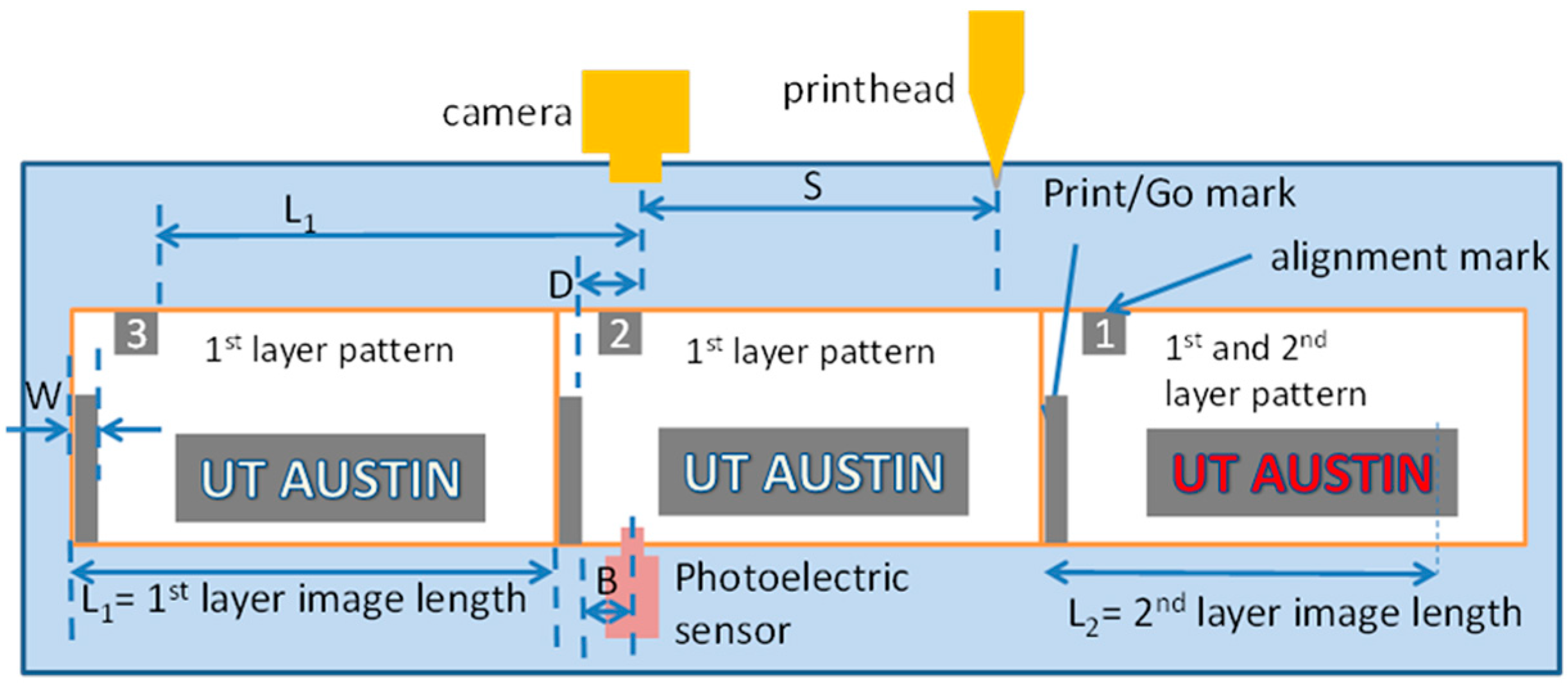
3.2. Alignment Strategy in the X Direction (Web Moving Direction)

After choosing the proper pre-offset image to print, we also need to determine the correct time to start printing. Therefore, we also need the X direction alignment, which is aimed at setting the right timing for the printhead to start printing the patterns. We use a photoelectric sensor with Print/Go mark to determine the printhead actuation moment. For example, as illustrated in Figure 4, we need to print a second layer pattern (UT AUSTIN filled in RED) on top of the first layer image. The alignment marks and Print/Go marks are placed at the ending positions of each copy of the first layer pattern (unfilled UT AUSTIN). The camera will first detect the alignment mark, and initiate the TCP/IP protocol. This triggers a chain of events, leading up to the availability of an error corrected print pattern ready for printing. When the Print/Go signal is detected by the photoelectric sensor, the print ready pattern is printed. The time delay between the detection of the alignment mark and the detection of the Print/Go signal on the same copy is called buffer time, and it should be set long enough to finish the processing, image loading and transfer tasks. In the actual setup, the buffer time can be adjusted by changing the value of B and D, which represent the distances between the photoelectric sensor and the camera to the Print/Go mark, respectively, as illustrated in Figure 4.
Figure 4. Alignment strategy in the X direction showing the relative positions of the printhead, camera, alignment mark, Print/Go mark and the photoelectric sensor.
Electronics 03 00624 g004

3.3. Software Development Using NI LabVIEW

We use LabVIEW from National Instruments (NI) to integrate all the functional modules needed. Our software performs three major roles: image acquisition, image processing and printer control.

4. Module Testing

4.1. Alignment Mark Detection

Whenever an alignment mark enters the field of view, it will be captured. The processed result is then used to select the corresponding pre-offset image, and the print command is sent out immediately. Figure 5 shows an offset testing result with 20 consecutive alignment marks captured by the camera. A non-flat behavior is typically expected due to sideways wander of the web. From the graph, the maximum sideways wander range of the web is calculated to be about 4 mm.
Figure 5. Detected positions of 20 consecutive alignment marks, indicating the web sideway wander of around 1.5–2 mm each way for this pass.
Electronics 03 00624 g005

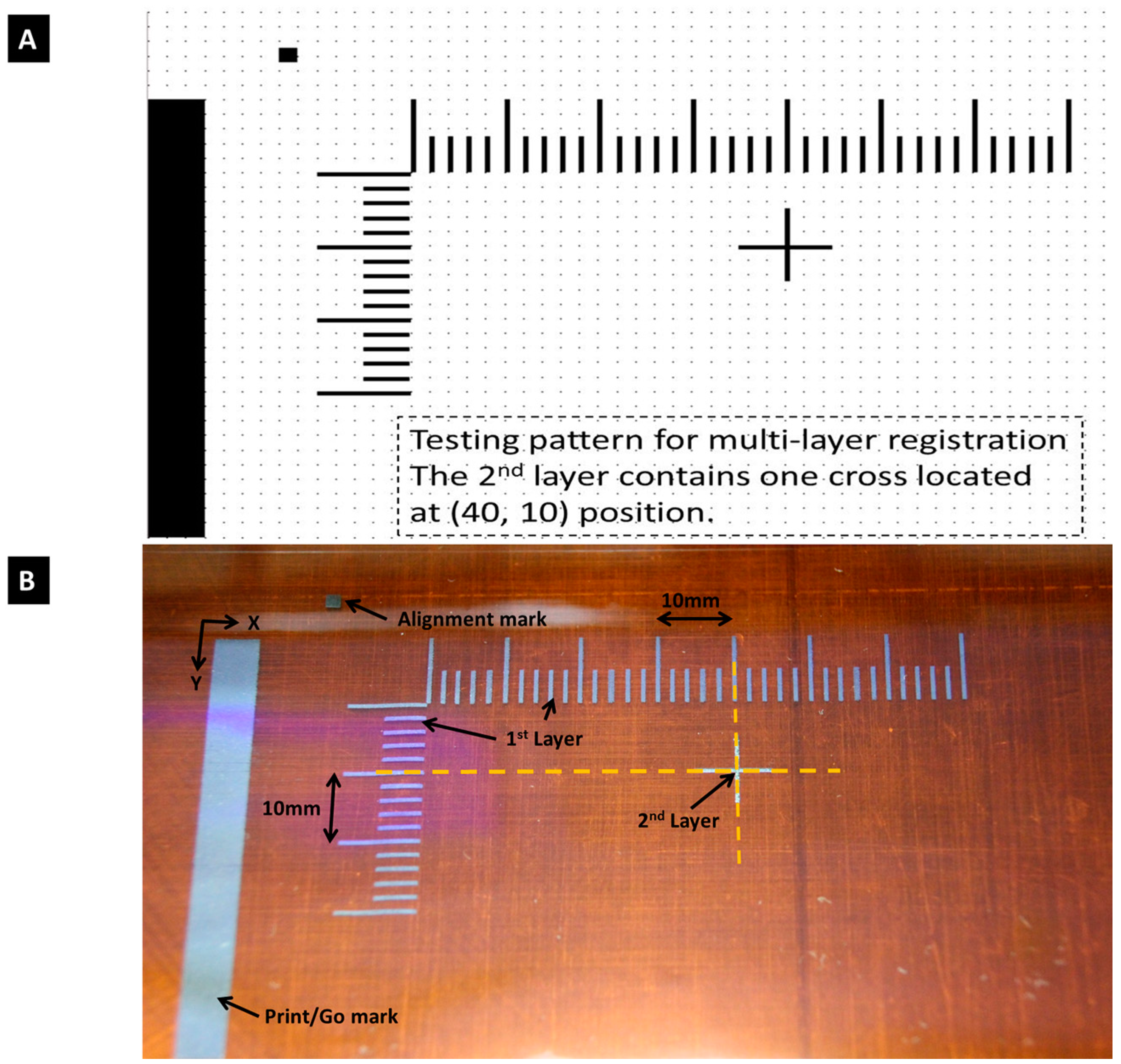
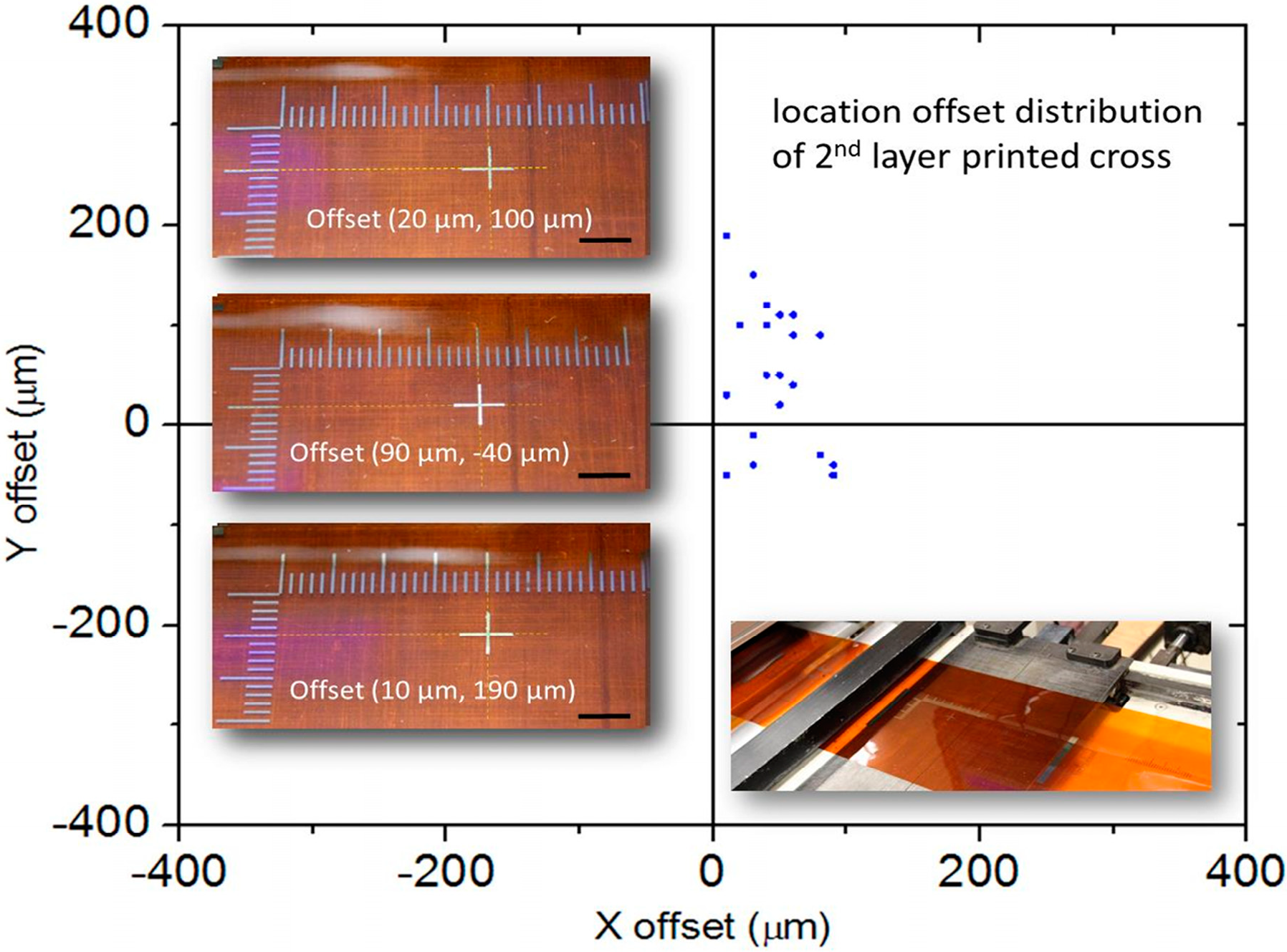
4.2. Registration for Multi-Layer Printing

We perform real-time aligned printing using a test pattern, as shown in Figure 6A. The first layer pattern contains a 2 mm × 2 mm square alignment mark, Print/Go mark and reference scales in X and Y directions. The second layer is a cross hair mark that is centered at X = 40 mm, Y = 10 mm location. In the experiment, we printed the first and the second layers using silver nanoparticle ink at a web rate of 5 m/min. The result is shown in Figure 6B, where the cross is printed at the desired location. We also perform continuous printing of 20 second-layer patterns to test its repeatability. The misalignment distribution with respect to the designed location results is shown in Figure 7, with inset pictures showing typical printed results on the web. As can be seen, for all copies, the off-registration errors are <100 μm in X and <200 μm in Y directions, which indicates the feasibility of our alignment strategy.
Figure 6. (A) Test pattern for aligned printing; (B) printed results showing registration of two layers with off-alignment less than 100 μm in both X and Y directions.
Electronics 03 00624 g006
Figure 7. Registration offsets distribution showing continuous printing of 20 second-layer patterns with ΔX < 100 μm and ΔY < 200 μm for all copies. The inset pictures have scale bars of 10 mm.
Electronics 03 00624 g007

5. Performance Overview

Although precise and effective algorithms are applied to ensure best registration accuracy, there are still several factors that need to be considered to minimize their effects to the system performance and auto registration accuracy. Factors that need further attention are:
  • The resolution of the printhead.
  • The time required to initialize the Print Server software.
  • The time between the print command being sent and the Print Server being ready to start printing.
  • Image acquisition and processing delays.
  • The number of PMBs or printheads which can be connected to a single PC.
It is challenging to precisely predict or guarantee the performance of the software, as there are a number of different factors which contribute to it. These factors include:
  • The operating system setup.
  • The PC hardware.
  • The other software or operations running on the PC.
  • The Print Server configuration.
Table 1. Limiting factors for registration error.
X Direction (absolute value)
Limiting factorsOffset introduced
Encoder error due to slip when start/stop100–200 μm
Printer delay (4 ms delay, web running is 5m/min)333 μm during 4 ms
Image file transfer delay (uncertain)Estimate ≈ 500 μm (500 KB file size) (*)
LabVIEW program image processing time (1 ms)80 μm
Actual tested offset<100 μm
Y Direction (absolute vale)
Limiting factorsOffset introduced
Printer nozzle offset70.5 μm
Sideway wander offset while transferring from FOV to printheadUp to 2000 μm
Camera resolution3 μm
Actual tested offset<200 μm
(*) Including PMB-PC via USB (250 MB/s), thus 500 KB needs 2 ms Hard disk readout time: for 5400 rpm hard drive, 100 MB/s thus 500 KB needs 5 ms Total 7 ms delay (≈500 μm).
To be specific for our system, some limiting factors affecting the overall system registration resolution are shown in Table 1. In the X direction, the introduction of Print/Go marks gives the system extra buffering time for file loading/transferring and provides the exact timing to start printing. In the print runs, the buffer length (B) is set at around 10 mm (adjustable) which gives about 120 ms buffering time when the web is running at 5 m/min. Thus, many issues related to PC performance are eliminated, and the alignment errors are controlled well within 100 μm. This error is mainly due to the slip of the encoder. In the Y direction, the main limiting factors come from the printer nozzle offset and the web sideways wander. The printer nozzles have a pitch of 70.5 μm, which is larger than the camera resolution. Thus, the offset values will be rounded and mapped to the nearest integer when choosing the pre-offset images, as shown in Table 1. Besides, after a correct second layer image is selected, and until the moment printing starts, the web would have moved sideways due to web wander, which is beyond our current control. From the design point of view, reducing the camera/printhead separation and the second layer pattern width would be helpful in minimizing the effect of this uncertainty. In order to further improve the alignment accuracy, dynamic position control of printhead location can be utilized. Currently, the position of the printheads is fixed relative to the substrate. Mounting the printheads on precision motors will provide an additional degree of freedom for future systems in order to achieve sub 10 μm alignment accuracy, however, with a small throughput penalty. To ensure high yield, enough tolerance should be given for off-registration when designing the device pattern. In the future, we will also consider the effects of substrate shrinkage and buckling on the alignment accuracy.

6. Conclusions

In this paper, we demonstrated a customized, machine vision aided roll-to-roll ink-jet printing system for high rate, high yield device fabrication. Based on an active alignment technique, we built up all the necessary modules and developed the software to realize auto-registration for multi-layer stacking. The X direction registration was realized by in-line capturing the alignment mark and determining the onset moment of printing. The Y direction registration was achieved by real time image processing to get the alignment mark offset, and selecting the pre-offset images to compensate for the deviation. Several limiting factors, including the resolution of the printhead, the time required to initialize the Print Server software, the time between the print command being sent and the Print Server being ready to start printing, Image acquisition and processing delays, and the number of PMBs or printheads which can be connected to a single PC, affect the overall system performance. Specifically for registration, the printer nozzle offset, camera resolution, encoder error, print delay, image processing delay, leads to a current registration error of about 100 µm and 200 µm for the X and the Y directions, respectively.

Acknowledgments

This work was supported by the Office of Naval Research (ONR) Small Business Technology Transfer (STTR) contract N00014-11-C-0704 monitored by Khershed Cooper. We would also like to acknowledge Ed Garcia from Industrial Inkjet Ltd and Kaj Larsen from KAJ’s Technical services for their valuable suggestion in setting up the system.

Author Contributions

Xiaohui Lin, Harish Subbaraman contributed to the system design, component selection, system setup, data analysis, and manuscript preparation. Zeyu Pan and Amir Hosseini contributed to data analysis and manuscript preparation. Chris Longe, Klay Kubena, Paul Schleicher, Phillip Foster, and Sean Brickey contributed to the alignment software development. Ray T. Chen contributed to overall system design, data analysis, and manuscript preparation.

Conflicts of Interest

The authors declare no conflict of interest.

References

  1. Parashkov, R.; Becker, E.; Riedl, T.; Johannes, H.; Kowalsky, W. Large area electronics using printing methods. Proc. IEEE 2005, 93, 1321–1329. [Google Scholar] [CrossRef]
  2. Jung, M.; Kim, J.; Noh, J.; Lim, N.; Lim, C.; Lee, G.; Kim, J.; Kang, H.; Jung, K.; Leonard, A.D.; et al. All-Printed and Roll-to-Roll-Printable 13.56-MHz-Operated 1-bit RF Tag on Plastic Foils. IEEE Trans. Electron Devices. 2010, 57, 571–580. [Google Scholar] [CrossRef]
  3. Noh, J.; Dongsun, Y.; Lim, C.; Cha, H.; Han, J.; Kim, J.; Park, Y.; Subramanian, V.; Cho, G. Scalability of Roll-to-Roll Gravure-Printed Electrodes on Plastic Foils. IEEE Trans. Electron. Packag. Manuf. 2010, 33, 275–283. [Google Scholar] [CrossRef]
  4. Bundgaard, E.; Krebs, F.C. Low band gap polymers for organic photovoltaics. Sol. Energy Mater. Sol. Cells. 2007, 91, 954–985. [Google Scholar] [CrossRef]
  5. Jørgensen, M.; Norrman, K.; Krebs, F.C. Stability/degradation of polymer solar cells. Sol. Energy Mater. Sol. Cells. 2008, 92, 686–714. [Google Scholar] [CrossRef]
  6. Jacobson, J.; Comiskey, B.; Albert, J. Microencapsulated electrophoretic display. U.S. Patents US5961804 A, 5 October 1999. [Google Scholar]
  7. Kim, C.A.; Myoung, H.J.; Kang, S.-Y.; Chung, H.-S.; Kim, G.H.; Ahn, S.D.; You, I.-K.; Oh, J.; Baek, K.H.; Soo, K. Towards a Colored Electronic Paper through a Fabrication of Color Microencapsulated Electrophoretic Display Panel. In Proceedings of Imid/Idmc 2006: The 6th International Meeting on Information Display/the 5th International Display Manufacturing Conference, Digest of Technical Papers, Daegu, Korea, 22–25 August 2006; pp. 1415–1418.
  8. Krebs, F.C.; Tromholt, T.; Jørgensen, M. Upscaling of polymer solar cell fabrication using full roll-to-roll processing. Nanoscale 2010, 2, 873–886. [Google Scholar] [CrossRef] [PubMed]
  9. Lin, X.; Ling, T.; Subbaraman, H.; Zhang, X.; Byun, K.; Guo, L.J.; Chen, R.T. Ultraviolet imprinting and aligned ink-jet printing for multilayer patterning of electro-optic polymer modulators. Opt. Lett. 2013, 38, 1597–1599. [Google Scholar] [CrossRef] [PubMed]
  10. Lin, X.; Ling, T.; Subbaraman, H.; Guo, L.J.; Chen, R.T. Printable thermo-optic polymer switches utilizing imprinting and ink-jet printing. Opt. Express 2013, 21, 2110–2117. [Google Scholar] [CrossRef] [PubMed]
  11. Subbaraman, H.; Pham, D.T.; Xu, X.; Chen, M.Y.; Hosseini, A.; Lu, X.; Chen, R.T. Ink-Jet Printed Two Dimensional Phased-Array Antenna on a Flexible Substrate. IEEE Antennas Wirel. Propag. Lett. 2013, 2, 170–173. [Google Scholar] [CrossRef]

