1. Introduction
Global carbon emissions caused by coal, oil and other fossil fuels have reached nearly 37 Gt CO
2 in recent years [
1]. Because of its large population and rapid economic growth, China’s CO
2 emission ranks the highest in the world, reaching 11.4 Gt in 2022. Except for carbon emissions, the considerable consumption of fossil fuels also leads to the increasingly serious air pollution [
2]. The main source of air pollution includes the industry sector, the transportation sector and buildings’ energy consumption. Among them, buildings’ energy consumption accounts for over one third of the total energy consumption in China, which results in a serious haze of pollution in the heating season [
3,
4,
5,
6]. Despite how some plans, the Air Pollution Prevention and Control Action Plan, for instance, proposed by the Chinese government, have contributed to a fossil fuel reduction in central heating to some extent, the consumption of scattered coal in rural areas should not be ignored, as it accounts for a large proportion of pollutant emissions in the heating season [
7,
8,
9]. It is reported that rural households consumed approximately 110 million tons of raw coal in 2018 in China [
10]. As a major proportion of rural households in China require heating during winter, the abundant use of scattered coal poses serious threats on air quality, public health and climate change [
11]. Moreover, centralized heating is usually not applicable for rural areas in Northen China, as the households are commonly scattered. Therefore, distributed heating plays a key role in heating in rural areas in Northen China. Nowadays, the low thermal-efficiency heating methods such as cooking stoves and traditional heating stoves are still widely used, which worsens the air pollution.
In recent years, great importance has been attached by Chinese governments to the use of renewable energy to replace conventional energy [
12,
13,
14,
15,
16]. Many policies have been released to facilitate the transformation of clean heating, such as the Winter Clean Heating Plan for Northern China, “Coal to electricity” and “coal to gas” initiatives, etc. The execution of these policies has contributed to the rapid development of clean energy heating in recent years [
17,
18,
19,
20]. Obviously, solar energy and biomass energy are good candidates for clean heating in rural areas, because they are cleaner than traditional heating methods, and they are suitable for distributed heating. Moreover, the wide application of various heat pumps plays an important role in the implementation of “coal to electricity” initiatives. On one hand, the heat pump is an energy-saving piece of equipment; on the other hand, the heat pump can help to consume electricity generated by clean energy sources. The most common heat pumps include air-source heat pumps (ASHPs), ground-source heat pumps (GSHPs) and sewage-source heat pumps (SSHPs). Therefore, clean-energy heating modes used in China at present mainly include solar heating, ASHPs, GSHPs and biomass heating [
21,
22,
23]. In some areas, SSHPs can also be used [
24,
25].
However, these clean heating methods are subject to high investment and operating costs, which limit the large-scale application of clean energy sources. In other words, once the investment and operating cost can be minimized and compared to that of traditional heating methods, the clean energy sources can be applied at a large scale. Additionally, these clean heating methods are also restricted by local conditions [
26]. In most cases, the clean heating methods cannot be used individually. For example, the solar energy is unstable and auxiliary heating equipment is usually needed, except for in solar thermal collectors [
27,
28,
29]. Additionally, biomass energy is usually restricted by the quantity of the resource, and the market price of the biomass briquette is very high in many areas [
30]. In addition, the application of the geothermal heat pump requires drilling, which increases the initial investment. Furthermore, the air-source heat pump is widely used at present, but in some severe cold regions, the coefficient of performance would decrease drastically [
31,
32]. Especially in high-humidity regions where frosting could occur, much additional energy is required for defrosting [
33,
34]. Therefore, it is hard to meet the increasing demand for heating if the energy sources are used individually, and the sources should be combined into a complementary system to achieve a large-scale application of clean heating [
35].
There is abundant research that focuses on the combination of different heating sources. One of the most common coupling systems is the solar-assisted-heat-pump system, especially the solar thermal collector coupled with the GSHP. Many scholars propose that solar energy can be well coupled with geothermal energy, as the geothermal energy extracted by the GSHP during the heating season can be supplemented by the solar thermal collector in summer [
36,
37,
38,
39,
40,
41]. Additionally, many experiments and simulation works have validated that solar energy can help to restore ground temperature and improve the overall performance of the GSHP [
42,
43,
44,
45]. Razavi et al. analyzed the performances of various solar-assisted ground-source heat pump (SAGSHP) systems based on TRNSYS simulations. It was found that the maximum annual coefficient of performance (COP) can reach 3.75, and the energy consumption diminishes by 8.7% compared to the GSHP standalone system [
46]. Similarly, Yang et al. tested the performances of a SAGSHP system in different heating modes, and the average unit COP is 3.61 [
47]. Additionally, the biomass boiler can also be coupled with other heat-source equipment. It usually acts as an auxiliary piece of equipment because of its stability and the limitation of the resource. For example, Konstantinos et al. tested the performance of a coupling system that includes a biomass boiler and a parabolic trough collector, and compared the economics of this coupling system with a heat pump powered by photovoltaic panels. It was found that the coupling system has a much higher cogeneration efficiency [
48]. Moreover, Zhang et al. presents a CHP (combined heating and power) system coupling a biomass boiler and a GSHP, and their results show that the system exergy efficiency can be reached at about 13.65% [
49].
For the design of a coupling system, the system composition, the heat-supply ratio of each piece of heat-source equipment, and the operation strategy of the system should be determined appropriately. Basically, the traditional design method cannot achieve the optimal configuration of the multi-source complementary heating system, because the heat supply and heat demand are easy to mismatch [
50,
51]. This results from the continuous change of the heating load. Therefore, sometimes the system composition can be inadequate, and the operation cost can be very high, which restricts the large-scale application of clean heating [
52]. Some scholars have investigated the economic optimization of a specific coupling system to enhance the energy efficiency [
53,
54,
55,
56,
57,
58]. For example, Arabkoohsar et al. used a genetic algorithm to optimize the multi-objective techno-economic functions environmentally for the problem of low load demand in summer [
59]. Similarly, Zhang et al. investigated the optimization of the heating system by using the AHP (Analytic Hierarchy Process) and FCE (Fuzzy Comprehensive Evaluation) methods [
60]. Additionally, Pirutiet et al. proposed an operating model based on the optimal combination of volume flow and supply temperature with the objective of reducing the minimum total annual energy consumption and operating costs [
61]. However, the buildings’ heating load and ambient temperature are kept fixed, leading to a mismatch between the heat supply and the demand and energy waste. To solve this problem, Gong et al. propose an optimization method for a combined cooling, heating and power system based on schedulable loads, and the optimal system shows a better economic performance compared with a system involving thermal-energy storage and demand response [
62]. Additionally, Yuan et al. investigated the performance of a complementary heating system of combined drying based on transient simulation, and their results show that the annual cost of the system reduces by 42.6% compared with other heating modes. Although this work is conducted based on transient simulation, it focuses on a specific system and does not consider other possible configurations of the complementary heating system [
63].
Additionally, some researchers focus on the optimal operation strategies of a complementary heating system. For example, Ma et al. examined the economic performance of a multi-energy complementary heating system under different control strategies. The results show that the heat-storage tank with a sufficient solar-energy mode can generate lower energy consumption costs and almost no CO
2 emissions [
64]. Lu et al. focus on the research of multi-time scale optimal operation scheduling for a complementary heating system, and the system economy is improved under distributed model predictive control [
65]. In addition, Dai et al. proposed an optimization method based on a belief rule base and evidential reasoning (BRB-ER) method. The results show that the proposed method can make the complementary heating system more efficient [
66].
Until now, there has been a lack of a unified design method for a multi-source complementary distributed heating system, especially one based on transient heating loads. How to choose suitable heating equipment for a specific project, and how to determine the capacity of each piece of equipment are still open questions. To solve this problem, a generalized structure of a multi-source complementary heating system is proposed in this work, based on which a mathematical model is established. According to the mathematical model, a coupling system can be built on TRNSYS software (version 17) for numerical simulation. Then, a three-step method is proposed for system optimization, including the preliminary selection of the system composites, the determination of the operation strategy for a specific system, and the optimization of the capacity of each piece of equipment. The proposed design method is applied in an actual project in a typical rural community in Dezhou City, China. The results show that the coupling system determined by the proposed method has obvious economic advantages, and the proposed method can be broadly applied for distributed heating.
The proposed design method provides a way to optimize a complementary system in terms of system composition, operation strategy, and equipment capacity. The establishment of the generalized structure and its mathematical model enables the quick calculation and convenient comparison of various schemes for a complementary heating system, and simplifies the complicated optimization problem to the capacity optimization of each piece of equipment. Therefore, the complex multi-dimensional optimization problem is avoided. The proposed design method can reduce the annual cost to a minimum value, and thus it can be widely applied for heating in rural areas in Northen China.
2. Materials and Methods
As mentioned in the Introduction section, a unified design method for a multi-source complementary heating system is necessary. To solve this problem, three questions need to be addressed: How can one obtain the most suitable configuration of a complementary heating system? How can one optimize the system-operation strategies in a transient simulation? How can one determine the capacity of each piece of equipment to minimize the investment and the operation cost? In this section, a three-step method is proposed to solve the above problems. In
Section 2.1, the logic for the optimization of a multi-source complementary system is illustrated. Then, a generalized structure of a multi-source complementary heating system is proposed in
Section 2.2, which acts as a basis for the selection of system composites. Moreover, according to energy conservation, mass conservation and the mathematical relationship between related parameters, the mathematical model of the generalized structure is established, as will be introduced in
Section 2.3. Furthermore, the following three subsections give brief explanations of the optimization method for system configuration, operation strategies and the equipment capacity of a complementary system, respectively.
2.1. Method for System Optimization
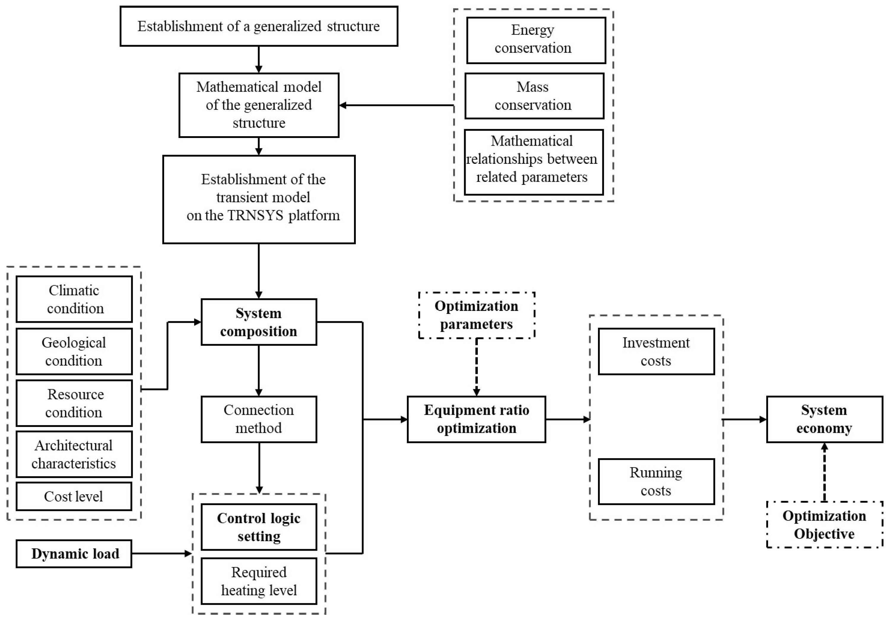
In order to improve the economy of the multi-source complementary heating system while ensuring the necessary heating level, the system composition, the heat-supply ratio of each piece of equipment, and the operation strategy should be optimized. Factors such as climatic conditions, architectural characteristics, resource conditions, engineering conditions, tariff policies and the performance characteristics of the equipment should be fully considered. The schematic diagram of the optimization logic is shown in
Figure 1.
In most work in the literature, the optimization process only focuses on the operation strategy and the equipment capacity for a specific system. In reality, the system configuration can be diversified, and it is also important to determine the most suitable configuration. However, if the system composition is also determined by using optimization algorithms, the optimization process can be very complicated. It is proposed that the system configuration can be preliminarily screened first according to some criteria, then the number of selectable schemes for the configuration could be reduced to a limited value. In this way, the optimization process can be simplified. Therefore, there will be three steps in the optimization process. The first one is to preliminarily screen out the system composition. The external conditions, as well as the characteristics of each piece of equipment should be considered. For example, in some cold areas where the humidity is also high in winter, the frost can be severe. In this case, ASHPs should not be used, as they will take much additional heat to defrost. After the system composition is preliminarily screened, the operation strategy of the coupling system should be preset. This is because the heating load changes continuously, and the operation strategy of the system under various degrees of heating load should be different. Finally, the best scheme for the complementary heating system is determined by optimization. Under the premise of ensuring the heat supply, the capacity of each piece of equipment is optimized to achieve the optimal economy. In many cases, some of the equipment can be eliminated after optimization, and only one or two pieces of equipment are left. The optimization can be realized based on transient simulations coupled with optimization algorithms. The three steps will be introduced in detail in the following subsections.
2.2. A Generalized Structure of a Multi-Source Complementary Heating System
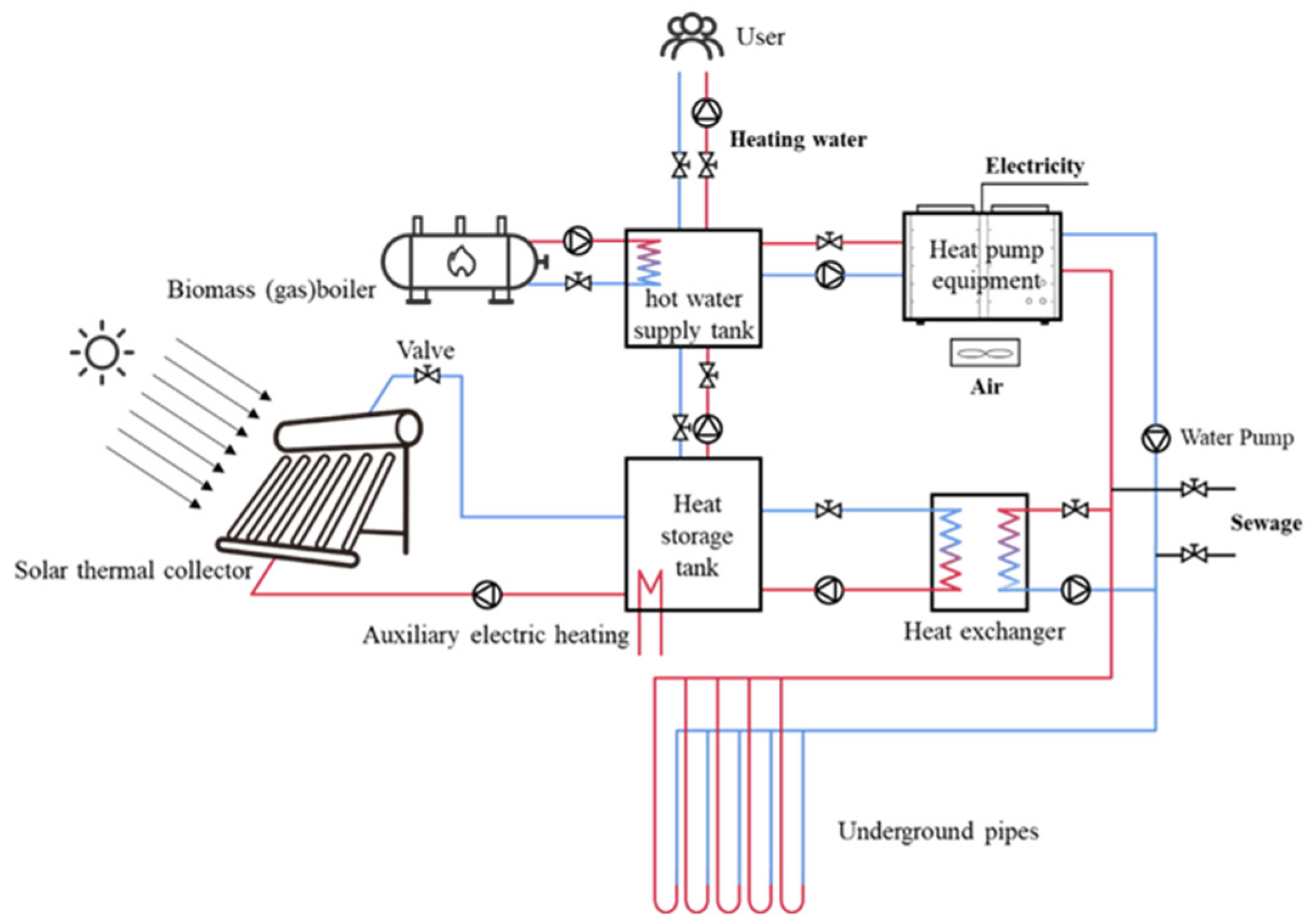
Based on the performance of energy-source equipment and energy-consuming equipment under variable conditions, a generalized structure of a multi-source complementary heating system is established at first, which is shown in
Figure 2. The so-called generalized structure refers to a combination of applicable energy-source equipment and energy-consuming equipment, as well as their connection types and operation strategies in the broad sense. In this generalized system, a solar thermal collector is connected to a heat-storage tank. Auxiliary heat sources, such as biomass boilers and gas-fired boilers, directly provide heat to a heating tank. The two tanks are connected by water pumps and valves so that the flow rate and pressure can be controlled. Additionally, a heat-pump system is included in this structure, which may be an independent ASHP, GSHP or SSHP, or a combination of these. The heat-pump unit can be driven by wind power, solar power and other renewable energy sources. The condensation end is connected to the heating tank for the supply of hot water, while the evaporation end of the heat pump unit is connected to low-temperature heat sources, including air, sewage, shallow-formation water and water from the storage tank. In addition, the heating tank supplies hot water to an indoor heat exchanger for heating, and the heat-storage tank can supplement heat to the soil in non-heating seasons for the temperature recovery of the underground temperature field, as it is directly connected to soil heat-exchange tubes. The red lines in this figure represent hot water provided by the heat sources, while the blue lines represent cold water returned from the users.
It is acknowledged that the optimization of a complementary heating system includes three aspects: the system composition, the operation strategy, and the capacity of each piece of equipment. As mentioned in the previous subsection, it is very difficult to optimize the three aspects only using optimization algorithms, because there will be too many optimization variables in this case. The generalized structure of a multi-source complementary heating system, which considers all types of energy sources that may be applicable, can be used to simplify the optimization process. Then, the mathematical model of the generalized structure is built on the TRNSYS platform. When designing the complementary heating system for a real project, the optional equipment within the generalized structure can be selected to form a specific system on the TRNSYS platform, based on the meteorological conditions and resource distributions. Then, the operation strategy of this specific system can be established. Therefore, the complex optimization problem is simplified to the capacity optimization of each piece of equipment. In addition, the establishment of its mathematical model enables the quick calculation and convenient comparison of various schemes of complementary heating systems. However, it should be noted that the generalized structure is only a conceptual model that shows how various heat sources are combined together; it does not mean that all equipment will be used for a specific project.
2.3. Mathematical Models of Each Piece of Heating Equipment
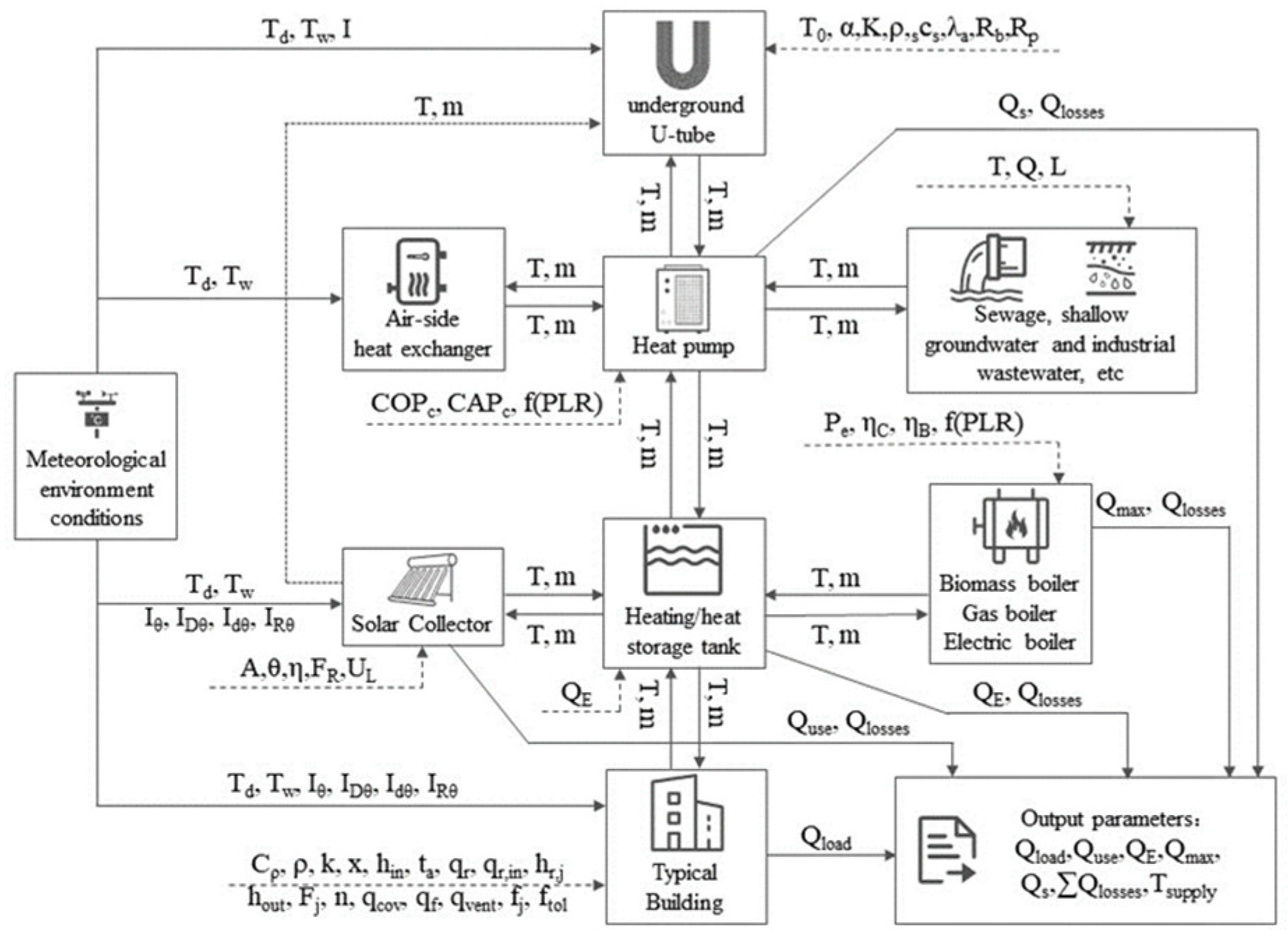
On the basis of the structure, a generalized transient mathematical model of the system can be built according to the mathematical model of the independent equipment, which takes account of the external parameters that affect the performance of the equipment, the inherent parameters of the equipment and the building, as well as the output parameters of the equipment. The external parameters include solar radiation intensity, ambient temperature, underground temperature field, etc., while the inherent parameters include the nominal working conditions COP of the heat pump, the heat capacity of the heat pump at nominal working conditions, the combustion efficiency of the biomass boiler, etc. Furthermore, the output parameters mainly refer to outlet-water temperature, water flow rate and heat provided by various pieces of equipment.
The established mathematical model is shown in
Figure 3, which is based on energy conservation, mass conservation and the mathematical relationship between related parameters. Apart from the influence of various parameters on the system performance, this generalized model also considers the coupling relationship among all parameters. According to the established mathematical model, a dynamic simulation program of a multi-source complementary heating system can be compiled on the TRNSYS software platform. This transient model can be used to realize numerical analysis, and the transient performance of the system can be obtained based on the simulation results. Then, the power consumption and heating level of the system can be obtained through integral analysis and the system economy can be analyzed.
The mathematical model of each piece of equipment used in modeling is introduced below. For a solar collector, the main factors that affect the heat collection efficiency include the structure of the solar collector, the solar radiation intensity, the ambient temperature, the inlet and outlet-water temperature and the installation angle of the collector.
The input of the calculation includes the process parameters, meteorological parameters and structural parameters of the collector, and the output refers to the operating parameters. The process parameters include the inlet temperature of the collector and the mass flow rate of the water; the meteorological parameters refer to the radiation on the collector and the ambient temperature, while the structural parameters include the total area of the collector array, the total thermal efficiency factor of the collector, the heat loss coefficient of the collector, the shortwave absorptivity of heat-absorbing plate and the shortwave transmittance of the collector. Moreover, the operating parameters include the outlet temperature of water, the heat generated by the collector and the heat loss.
The control equation is used to calculate the solar-collector efficiency, which usually applies the Hottel–Whillier equation:
where
A is the total area of the collector array, m
2;
FR is total thermal efficiency factor of the collector;
IT is total radiation on the solar collector, kJ/(h·m
2);
m is the flow rate under the operating conditions, kg/h;
Ta is ambient temperature, °C;
Ti is the inlet temperature of the collector, °C;
UL is the total heat loss coefficient per unit area of the collector, kJ/(h·m
2·K); α is the shortwave absorptivity of the heat-absorbing plate;
τ is the shortwave transmittance of the collector; and
τα is the shortwave transmittance of the collector in the vertical incidence of the sun.
For heat pumps, the input in the calculation includes the characteristic parameters and the process parameters. The characteristic parameters include the COP at the nominal working conditions, the heating capacity at nominal working conditions, and the partial load rate. Additionally, the process parameters include the inlet temperature and the outlet temperature. Furthermore, the output includes the power consumption, the actual heating load, and the heat generated by the heat pump.
For the ASHP and SSHP, the actual heating load can be calculated as
where
m is the water flow of the heat pump, kg/h and
cP is the specific heat capacity of water 4.190 kJ/(kg·K). Additionally, the actual COP can be calculated based on the heating load and the power consumption:
where
COPC is the
COP at nominal working conditions;
COPr is the ratio of
COP on the performance curve provided by the manufacturer to nominal working conditions
COP;
CAPC is the heating capacity at nominal working conditions;
CAPr is the ratio of the heating capacity on the performance curve provided by the manufacturer to the heating capacity at nominal working conditions; and
Fflp and is the ratio of the partial load rate to the rated power of the equipment.
For the GSHP, the ground-heat exchanger should also be modelled accurately. The heat-conduction model is applied for the heat-transfer analysis of the ground heat exchanger, which is regarded as cylindrical in numerical calculations. The two-dimensional non-steady-state heat-conduction differential equation is shown below:
where
is the thermal diffusivity m
2/s;
k represents the soil thermal conductivity w/(k·m); and
is the geothermal-specific heat J/(m
3·k). Usually, the finite-control volume method can be applied to solve the above equation.
For the biomass boiler, the input in the calculation includes the inlet-water temperature, the heat capacity of the boiler, the thermal efficiency of the boiler, the partial load rate, and the fuel combustion efficiency. In addition, the output mainly refers to the outlet-water temperature, the heat generated by the boiler, and the heat loss. For the biomass boiler, the temperature at a set outlet-water temperature is determined as follows:
where
tout is the outlet-water temperature, °C;
tin represents the inlet-water temperature, °C;
Qfluid is the actual heat capacity of the boiler, kW;
Qfuel denotes the heat released by fuel combustion, kW; and
ηB is the thermal efficiency of the biomass boiler, %.
2.4. Basis for the Selection of the System Composites
As is mentioned in the previous subsection, the selection of the system composites should take the local conditions into consideration, so as to achieve a good performance of the equipment. In reality, it is difficult to propose universally applicable standards for each kind of heating equipment. For example, there are various solar-thermal panel technologies, and many factors need to be considered to determine which one should be used. Therefore, in this work, only some fundamental standards are proposed, which can be used as references in an actual project. The recommended selection basis for various pieces of equipment is summarized in
Table 1. For the solar collector, the solar radiation intensity is the most important factor, as it is not cost-effective to use solar energy in areas with a low solar radiation intensity. For the ASHP, one important meteorological parameter except for temperature is the relative humidity. It is reported that when the outdoor ambient temperature is below 0 °C and the relative humidity is above 65%, the amount of frost will be severe, which makes the ASHP not suitable for application. Additionally, the recommended selection basis for GSHP is proposed by Fan et al. A suitability parameter that considers the geological conditions, the characteristics of the geothermal field, and the thermal properties of rocks is used to judge whether a GSHP is appropriate for use [
67]. Moreover, the distance to the sewage works is the key factor in determining the suitability of the SSHP. Furthermore, the most important factor limiting the use of biomass boilers is the amount of biomass resources around the user. Certainly, in an actual project, the selection of the equipment should also consider other practical factors such as construction conditions and the type of buildings.
After a preliminary screening, some heat-source equipment will be excluded. In most cases, the number of selectable pieces of equipment for the coupling system will be less than three. Therefore, the number of selectable schemes for the coupling-system composition in an actual engineering project will be limited. The best scheme for a specific project should be determined according to the optimization method, which will be introduced in the following subsections.
2.5. Determination of the Operation Strategy for a Specific System
For a specific multi-source complementary heating system, the operation strategy should be preset in the TRNSYS software to achieve a numerical simulation. Take a coupling system that includes three different pieces of heat-source equipment as an example; the turn-on scheme of each piece of equipment is determined by the temperature of the water coming out of the heating tank. Three comparison temperatures T
1, T
2 and T
3 are set to form four temperature ranges, and the equipment turn-on schemes are listed in
Table 2.
When the heating temperature rises and exceeds a certain target value, one of the pieces of working equipment needs to be turned off to save energy. However, the closing temperature of the equipment should not coincide with the opening temperature, otherwise it will lead to the frequent starting and stopping of the equipment, and the service life of the equipment will be affected. Therefore, a temperature-control accuracy is set separately for each piece of heating-source equipment. When the heating temperature exceeds the sum of the opening temperature and the temperature control accuracy, one of the pieces of working equipment can be shut down. Three comparison temperatures T
4, T
5 and T
6 are set to determine whether the equipment is turned off or not.
Table 3 lists the equipment turn-off schemes.
The sequence of operation of each piece of equipment is determined by the operating cost. For a coupling system that includes various pieces of heat-source equipment, the sequence of operation should be solar thermal collector > SSHP > GSHP > ASHP > biomass boiler. This is because the operation cost of the solar thermal collector is the lowest. Moreover, the COP of the SSHP is the highest among all types of heat pump, while the ASHP is the lowest. Furthermore, the biomass boiler is suitable as an auxiliary heat source because of its stability.
2.6. Optimization of the Capacity of Each Piece of Equipment
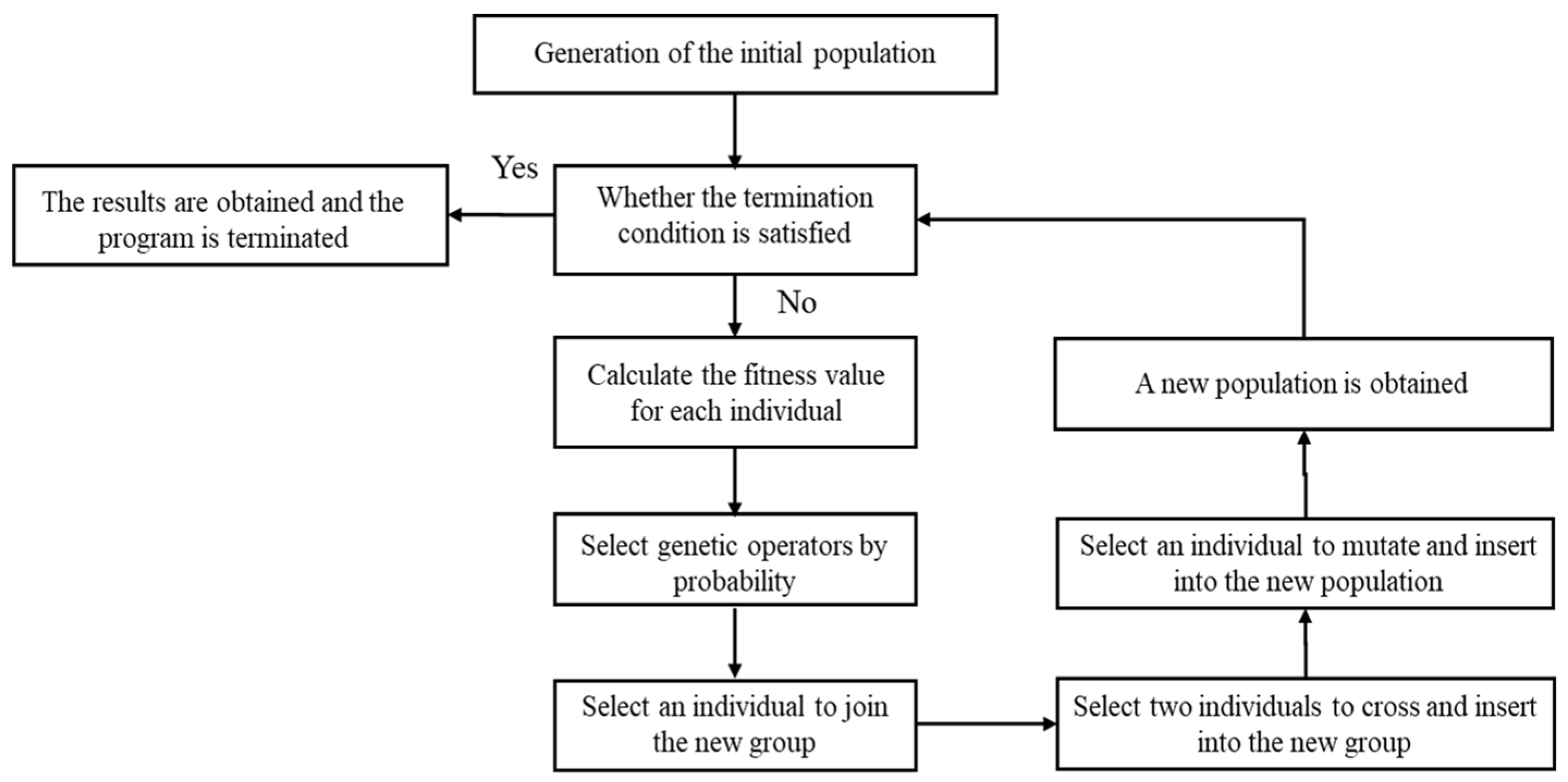
Under the premise of ensuring the heating temperature, the capacity of each piece of equipment in the system should be optimized. The GenOpt optimization program can be coupled with TRNSYS software to optimize the capacity of each piece of heating equipment. The genetic algorithm is applied in this work to search for the best solution automatically. A schematic of the optimization process is shown in
Figure 4. The initial configuration of the system, i.e., the capacity of each piece of equipment, is randomly generated. Then, acting as the objective function, the annual cost of the system is calculated. A new population can be obtained based on the genetic algorithm, and the process is iterated 200 times to obtain the final solution.
The capacity of each piece equipment is taken as the optimization variable, and the energy balance is considered the constraint. Moreover, the annual cost is set as the objective function, which includes the annual operating costs and the converted investment costs. It should be noted that the total investment cost should include the equipment cost, the control system cost, the installation cost or the construction cost. The annual converted investment cost is determined by using the following equation:
where
A is the annual converted investment cost,
P is the total investment,
i is the loan interest rate and
n is the equipment life.
Moreover, the constraints need to be determined as follows in the optimization process:
where
Qequ,i is the actual heating power for the
i-th piece of equipment,
Quser,h is the heating load, and
Qequ,c is the rated heating power of the
i-th piece of equipment.
3. Results and Discussions
In this section, a case study for an actual project in a rural area in Northern China is introduced to show the application of the proposed method. The annual heating load is calculated first, followed by a preliminary screening of the system composition. The ASHP, GSHP and the biomass boiler are used to form a complementary heating system. Then, a hierarchical control logic is adopted as the operation strategy, and the capacity of each piece of equipment is optimized by a combination of transient simulations and genetic algorithms. The results show the optimal capacity of each equipment is the following: the GSHP, 369 kW, the ASHP, 430 kW and the biomass boiler, 384 kW. Moreover, the heat produced by the GSHP accounts for over a half of the total heating load, and that generated by the other two pieces of equipment is at a same level. Furthermore, it was found that the optimization results are highly sensitive to the price of the biomass pellets, the COP of the ASHP, the cost of the ASHP and the cost of the GSHP.
3.1. Details of the Case Study
The proposed design method for a multi-source complementary heating system is applied in an actual project in a typical rural community in Dezhou City, China. The community is called Miaofuan, which is located in the plain area in China. This community is relatively rich in biomass resources, which are mainly corn and wheat straw, with an annual output of about 2000 tons. There are rural cooperatives next to the community, which can be used as a biomass-storage and -processing site.
There are eight six-story residential buildings in this community, and the exterior walls of the buildings are not insulated. The building area is 22,000 m
2, and the actual heating area is 20,000 m
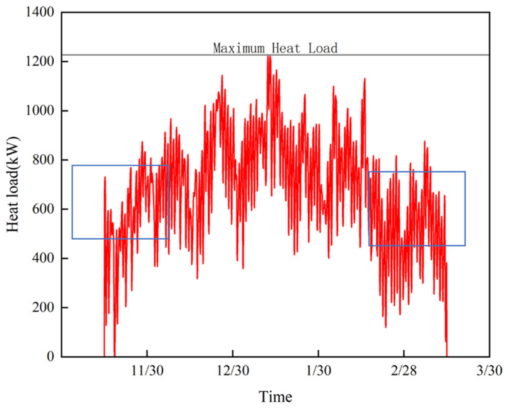
2. The heat supply starts from 15 November to 15 March of the following year. The heating load for a whole year, as shown in
Figure 5 is calculated by using DeST software (version 2.0). It is illustrated that the heat load reaches the peak from December to February of the following year. Besides, during the beginning and ending period of the heating season, the heat load is relatively low, as indicated in the blue box in the figure.
The annual maximum heat load reaches 1224.7 kW, and the cumulative annual heat output is 1,965,617.45 kWh.
3.2. Preliminary Screening of the System Composition
According to meteorological data in Dezhou City, the annual solar radiation of the horizontal plane is approximately 6357 MJ/m2. However, the annual sunshine duration is around 2483.6 h, less than 3000 h. In addition, the buildings have six stories, with a limited space on the roof. Thus, the solar thermal collector is not used in this project. Moreover, Dezhou City is dry in winter, with an average relative humidity of 45% during the heating season. In rare cases, the relative humidity can reach up to 60%. Thus, an ASHP is not eliminated in the screening process. Furthermore, the community has abundant biomass resources, with an annual output of nearly 2000 tons of corn and wheat straw. Therefore, the biomass boiler can be selected. In addition, there are no sewage works near the community.
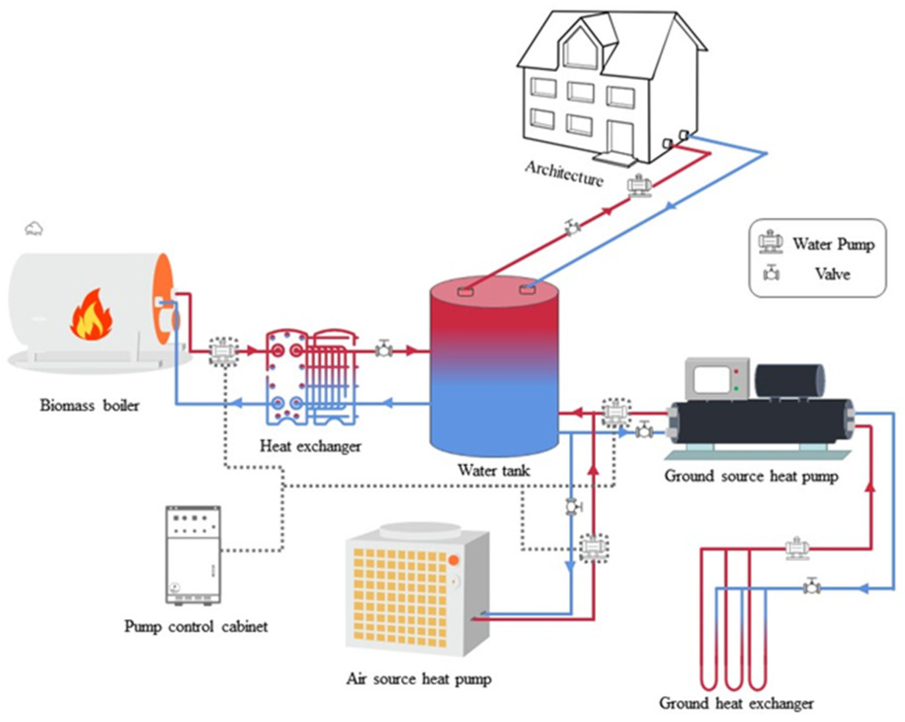
To sum up, the selectable heat-source equipment after a preliminary screening includes an ASHP, a GSHP and a biomass boiler. A complementary system after a preliminary screening can be established, as shown in
Figure 6. The red lines in this figure represent hot water provided by the heat sources, while the blue lines represent cold water returned from the users. Additionally, the dashed lines represent electric signal control.
3.3. Operation Strategies of the Complementary System
A hierarchical control method is adopted in this project, which controls the start and stop of the heat-source equipment by detecting the heating temperature Tg and the outdoor ambient temperature Ta. It is known that soil can maintain a relatively stable temperature in winter, and the COP of a GSHP is less affected by the ambient temperature. Therefore, a GSHP is used at first during the heating season. As for the ASHP, the COP varies with ambient temperature, so the operating costs of ASHPs should be compared with the biomass boiler to judge which piece of equipment is preferentially used. A simple judgment method is to compare the ambient temperature with the outdoor-temperature equilibrium point Tc. At this equilibrium temperature, the COP of an ASHP corresponds to a critical-value COPc, indicating that the cost of electricity consumed by an ASHP is equal to the cost of fuel consumed by a biomass boiler to produce the same amount of heat. If the temperature is higher than the equilibrium point, an ASHP is preferred; otherwise, a biomass boiler is preferentially used. As the COP of an ASHP and the ambient temperature is a one-to-one correspondence, the outdoor-temperature equilibrium point Tc can be easily established.
The critical
COPc value is calculated as follows:
where
Ce is the price of electricity, CNY/kWh;
Cb is the unit price of biomass pellets, CNY/kg;
ηb is the combustion efficiency of the biomass boiler, %; and
Hb is the calorific value of biomass pellets, taken as 17,908 kJ/kg.
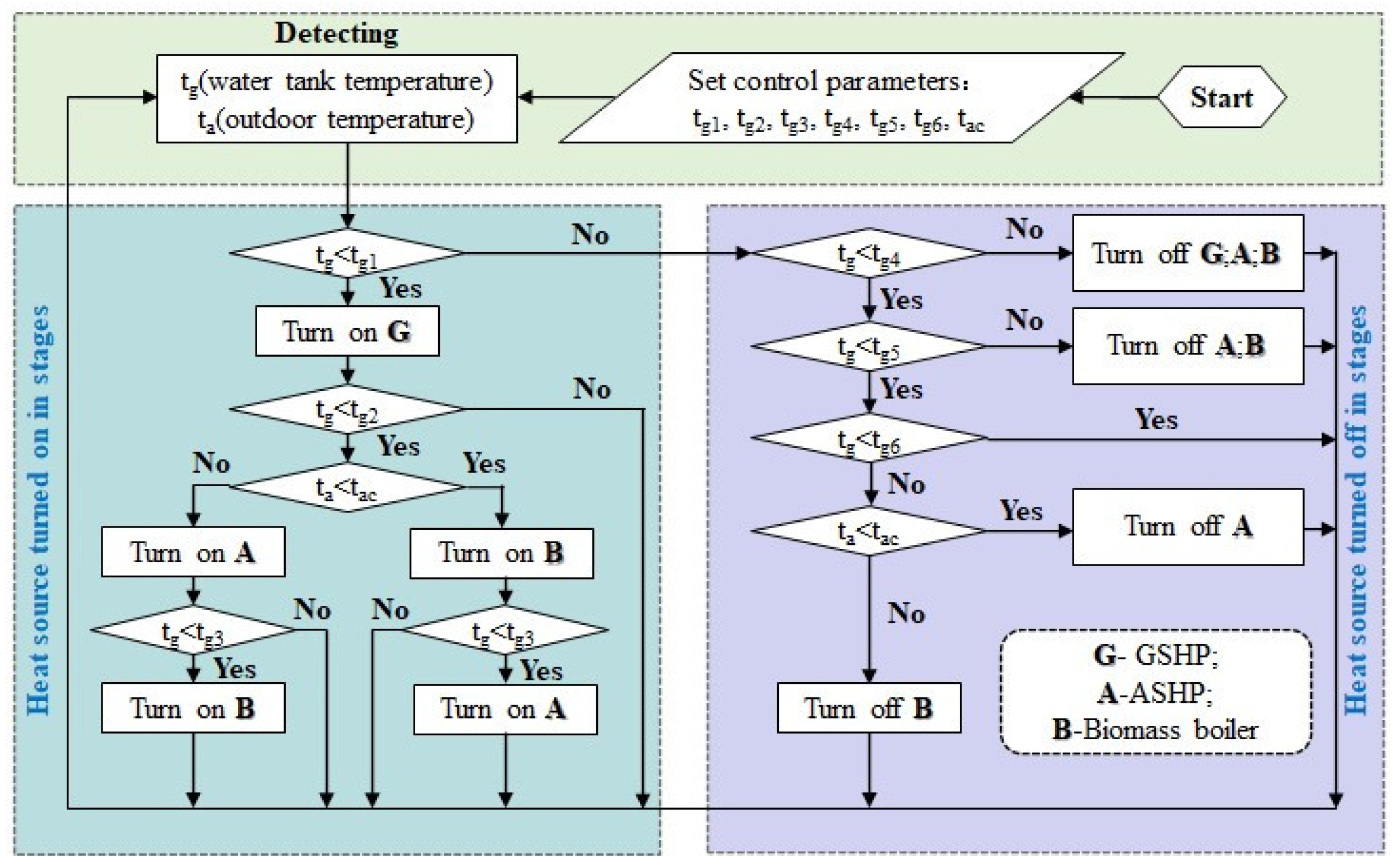
The control strategy is illustrated in
Figure 7. In this figure, G represents a GSHP, A refers to an ASHP, and B is biomass boiler; 0 means that the equipment is off, and 1 indicates that the equipment is on. T
g1, T
g2 and T
g3 are set as the turn-on temperature for each piece of heat-source equipment, which are 40 °C, 37 °C and 34 °C, respectively. T
g4, T
g5, and T
g6 are the turn-off temperatures, which are 45 °C, 41 °C and 37 °C, respectively.
The equipment’s turn-on strategy is as follows:
① When Tg < 40 °C, turn on the GSHP;
② When 34 °C < Tg < 37 °C, the ambient temperature Ta will be compared with the outdoor critical temperature Tac. If Ta > Tac, open the ASHP and the GSHP, otherwise the biomass boiler and the GSHP are turned on;
③ When Tg < 34 °C, all the three heat sources are turned on.
The equipment’s turn-off strategy is:
① When Tg > 45 °C, all the three heat sources are turned off;
② When 41 °C < Tg < 45 °C, the biomass boiler and the ASHP are turned off, and the GSHP is kept on;
③ When 37 °C < Tg < 41 °C, the ambient temperature Ta is be compared with the outdoor critical temperature Ta. If Ta > Tac, the biomass boiler is turned off and the GSHP and the ASHP are kept on. If Ta < Tac, the air-source heat pump is turned off, and the biomass boiler and the GSHP are kept on.
3.4. Modelling and Optimization of the Complementary System
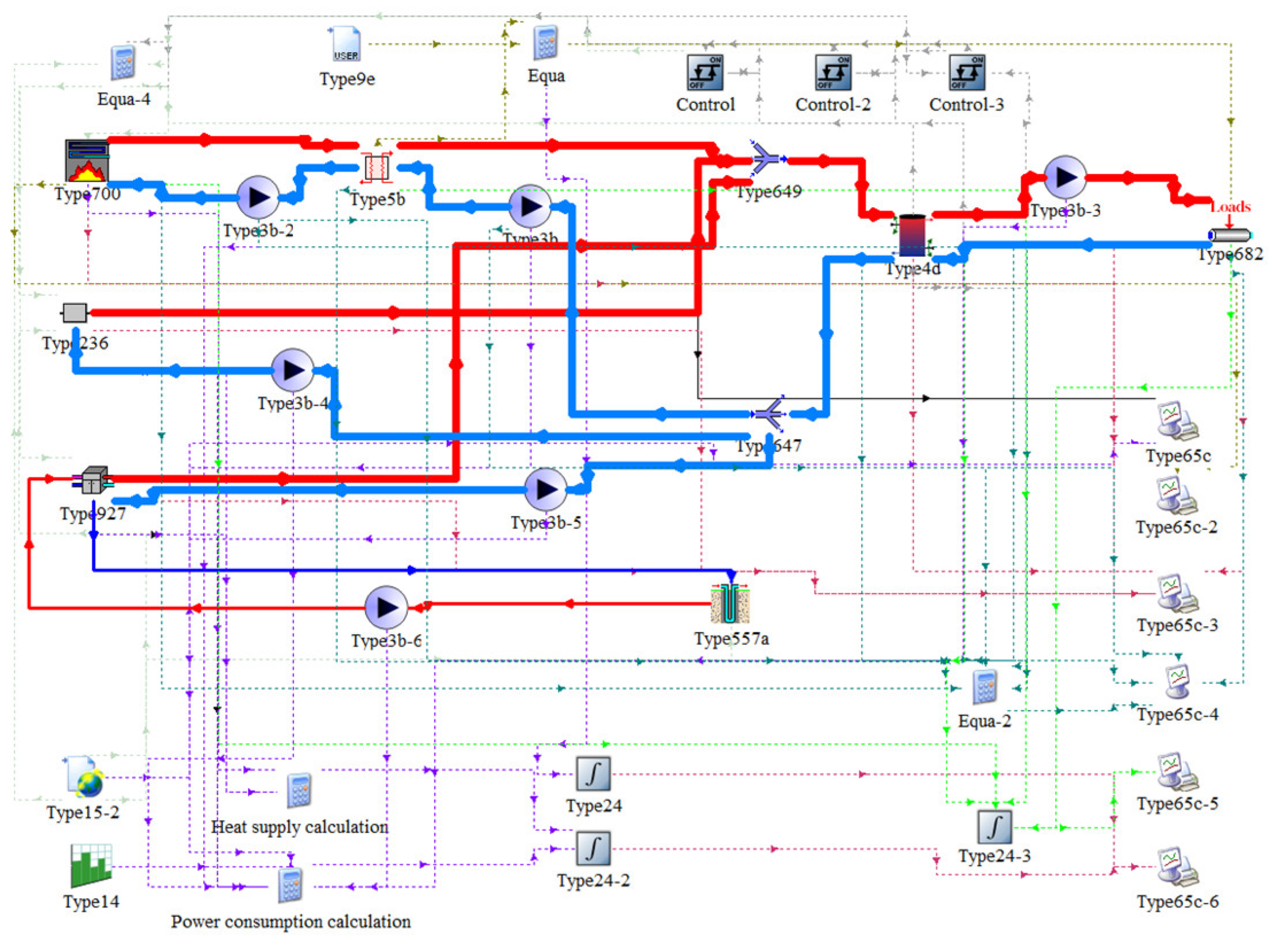
According to the physical model and the operation strategies, a simulation model of the complementary system is established by using TRNSYS software, which is shown in
Figure 8. In this figure, the red solid lines represent hot water provided by the heat sources, while the blue solid lines represent cold water returned from the users. Additionally, the purple dotted line represents the calculation of heating and power consumption of type700, as well as the calculation and integration of power consumption of the pump. The green dotted lines indicate calculation, integration and output for type700, 5b, 4d and 628. The black dashed lines represent the operation of the controller. The cyan dashed line is a result output for type700, 5b, 4d, 628 and each pump. The red dashed lines represent the output element.
The corresponding modules used in TRNSYS are summarized in
Table 4. This model can achieve the real-time calculation of parameters such as heating temperature, power consumption, heat supply, etc.
Under the premise of ensuring the heat supply, simulations are carried out with various heat-supply ratios. The annual cost of each case can be obtained through simulations, which are set as the optimized objective functions. The parameters that affect the annual cost are listed in
Table 5.
3.5. Simulation and Optimization Results
The optimization results are listed in
Table 6; the optimal heat-source equipment ratios are the following: for the GSHP, 369 kW, for the ASHP, 430 kW and for the biomass boiler, 384 kW. Therefore, for this specific project, none of the three pieces of equipment are eliminated after optimization, and the best scheme is the combination of the three piece of equipment. Other parameters, such as annual cost and total power consumption, are also listed in this table.
In addition, the heat supply of each piece of equipment is shown in
Figure 9. It is illustrated that the total heat production can well satisfy the heat load under this system scheme. Additionally, it is shown that the total heat produced by the GSHP accounts for approximately 55% of the total heating load, because it is preferentially used during the heating season, while the heat produced by the other two pieces of equipment are almost at the same level. The heat produced by the ASHP accounts for 21%, and that of the biomass boiler takes up around 24%.
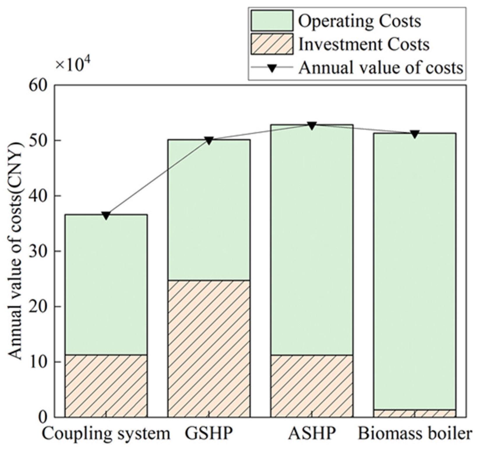
The economic advantages of this coupled system can be analyzed by comparing its annual cost with those of individual pieces of equipment. TRNSYS software allows us to perform simulations for systems consisting of various individual pieces of equipment, and the results show that the power consumptions of the GSHP, ASHP and biomass boiler are 462,428.11 kWh, 756,746 kWh and 42,048 kWh, respectively, while the biomass consumption of the biomass boiler is 397,235 kg. The annual cost, operation cost and the converted investment cost for the four different systems are shown in
Figure 10. It is demonstrated that the annual cost of the coupling system is the lowest among the four systems, much lower than that of the GSHP, ASHP, and biomass boiler alone. For example, the coupling system is 26.7% lower than that of the GSHP system. The investment cost of the coupling system is much lower than that of the GSHP system, mainly because wells need to be drilled for use of the GSHP, which increases the investment cost. Additionally, the investment cost of the coupling system is comparable to that of the ASHP system, although the coupling system includes the GSHP. This is because the COP of the ASHP will reduce sharply when the ambient temperature becomes very low. However, the heat load will reach the peak during severely cold days. To satisfy the peak heat load only by an ASHP, the capacity should be very large, leading to a very high investment cost. Also, because of the low COP during the severely cold days, the operating cost of the ASHP system will also be very high, leading to the highest annual cost of the system. Moreover, the investment cost of the biomass boiler system is the lowest, because this heating mode is stable, and the prices of the biomass boiler are not as high as the heat pumps. However, the operating cost of this system is the highest, because of the low calorific value and the high prices of biomass pellets. The coupling system can reduce the operating cost, since it takes the biomass boiler as a supplementary heating mode when the heat load reaches its peak.
Additionally, the complementary system is also beneficial to environment protection and sustainable development. Obviously, solar energy is suitable for clean heating in rural areas. Additionally, the biomass boiler involved in the generalized structure is also an ideal candidate for heating in rural areas, although it also leads to some emissions of NOX. The main reason for this is that the use of biomass resources for heating is an important method of resource reuse, and there is no better way to dispose of biomass resources. In addition, the application of various heat pumps is important. The heat pump is a piece of energy-saving equipment, and it is suitable for distributed heating. Moreover, the heat pump can help people to consume electricity generated by clean energy sources. In other words, if the electricity used by heat pumps is generated from renewable energy sources, the heat pumps can also be regarded as environmentally friendly. Additionally, the full use of the valley’s electricity can further reduce the operating cost.
Therefore, the coupling system consisting of various pieces of heat-source equipment are important for heating in rural areas in Northen China, in terms of economics, the environment and sustainability.
3.6. Discussions
The optimization results are affected by many parameters. In other projects or areas, the parameters listed in
Table 5 can be different, resulting in different heat-supply ratios for each piece of equipment, or even a different composition of the system. Six typical parameters in
Table 5, including the cost of a biomass boiler, the price of biomass pellets, the cost of an ASHP, the COP of an ASHP, the cost of a GSHP and the COP of a GSHP, are selected for sensitivity analysis. The initial values of these parameters are increased and decreased by 10% and 20%, respectively. Under the premise of ensuring a heat supply at the same level, the heat supply ratios of the three pieces of equipment are optimized for these cases. The optimization results are shown in
Table 7.
It can be seen that the optimization results are not sensitive to the cost of a biomass boiler, because the price of the biomass boiler is not high compared to other equipment. However, the price of the biomass pellets affects the optimization results remarkably. A 20% reduction in the price will lead to the elimination of the ASHP because of the operation cost of the biomass boiler will be an obvious advantage compared to that of an ASHP. Similarly, when this price increases by 10%, the best scheme is to use an ASHP as the only piece of heat-source equipment. Moreover, both the cost and COP of the ASHP have significant influences on the optimization results. When cost of an ASHP decreases by 10%, the economic advantages of the other two pieces of heat-source equipment will vanish, while when it rises by 20%, the heating load it carries will be taken up by the GSHP. Also, as the COP of the ASHP decreases by 10%, it will be lower than three, and the ASHP should not be used anymore. Furthermore, the COP of the GSHP has less impact on the optimization results, and only when it rises up to five will the system composition be changed. Additionally, a 20% reduction in its COP will lead to no change in the configuration, mainly because the operation cost is still low. In addition, a 20% decrease in GSHP’s cost will not change the heat-supply ratio, while a small increase will make the ASHP become the only usable piece of heat-source equipment.
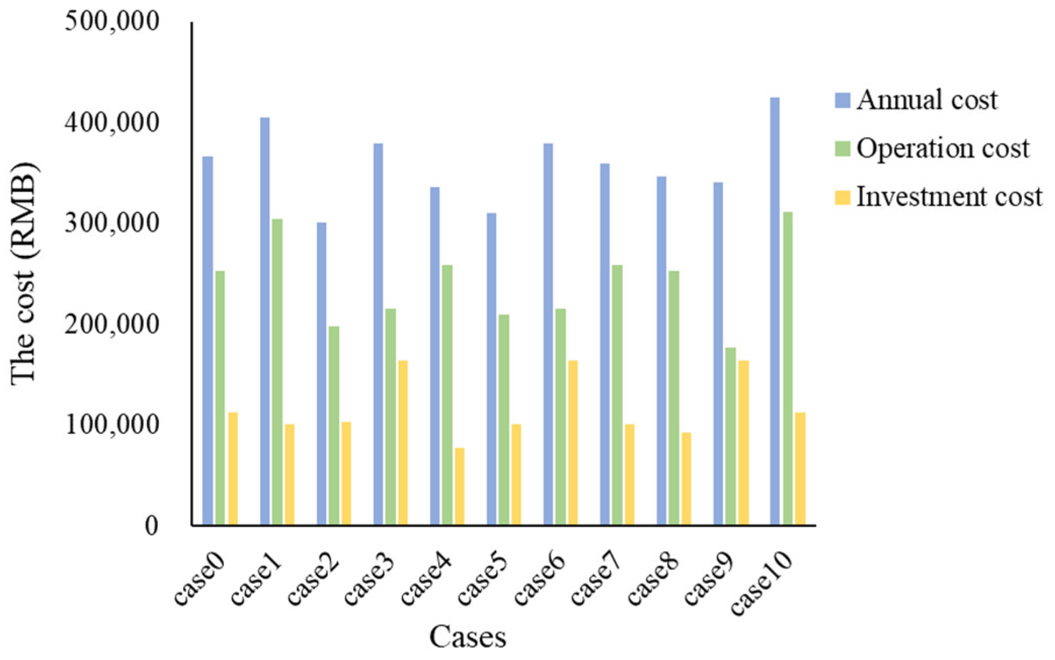
To clarify the impacts of the factors on the performance of the optimal system, ten cases are selected to show how uncertainty affects the economic performances of the optimal system. The optimal configuration obtained by the optimization is denoted as the basic case (case 0), and the configuration is the following: for the GSHP, 369 kW, for the ASHP, 430 kW, and for the biomass boiler, 384 kW. The other ten cases are described in
Table 8:
The economic performance of the ten cases is evaluated by a combination of transient simulations and optimizations, and the results are show in
Figure 11,
Figure 12 and
Figure 13.
Figure 11 shows the economic performance of the system in the ten cases. It can be seen that the annual cost of the system in case 2 is the lowest, approximately 18% lower than that of the basic case. In this case, the price of the biomass pellets decreases by 20%, and a higher capacity of the biomass boiler is used for the optimal configuration, while the ASHP is excluded. Moreover, a reduction in the cost of ASHPs and GSHPs can change the optimal configuration of the complementary heating system, and can achieve a lower annual cost compared with the basic case. Moreover, when the COP of the ASHP increases by 20%, the optimized configuration will be the ASHP itself, and the annual cost can reduce by over 15%. Similarly, a 20% increase in the GSHP’s COP can lead to a 7% reduction in the annual cost. Furthermore, for case 10. in which the COP of the GSHP decreases by 20%, the optimal configuration is not changed. This is because the operation cost of the GSHP is still competitive compared with that of the ASHP and the biomass boiler. However, both the annual cost and the operation cost will be increased markedly. In addition,
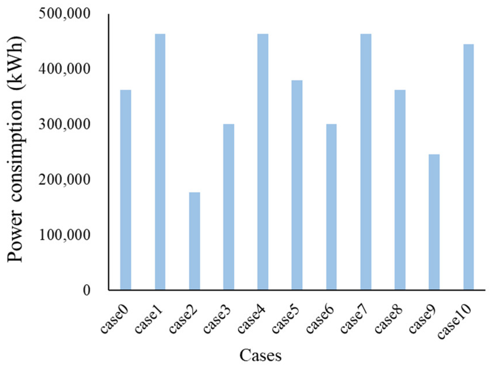
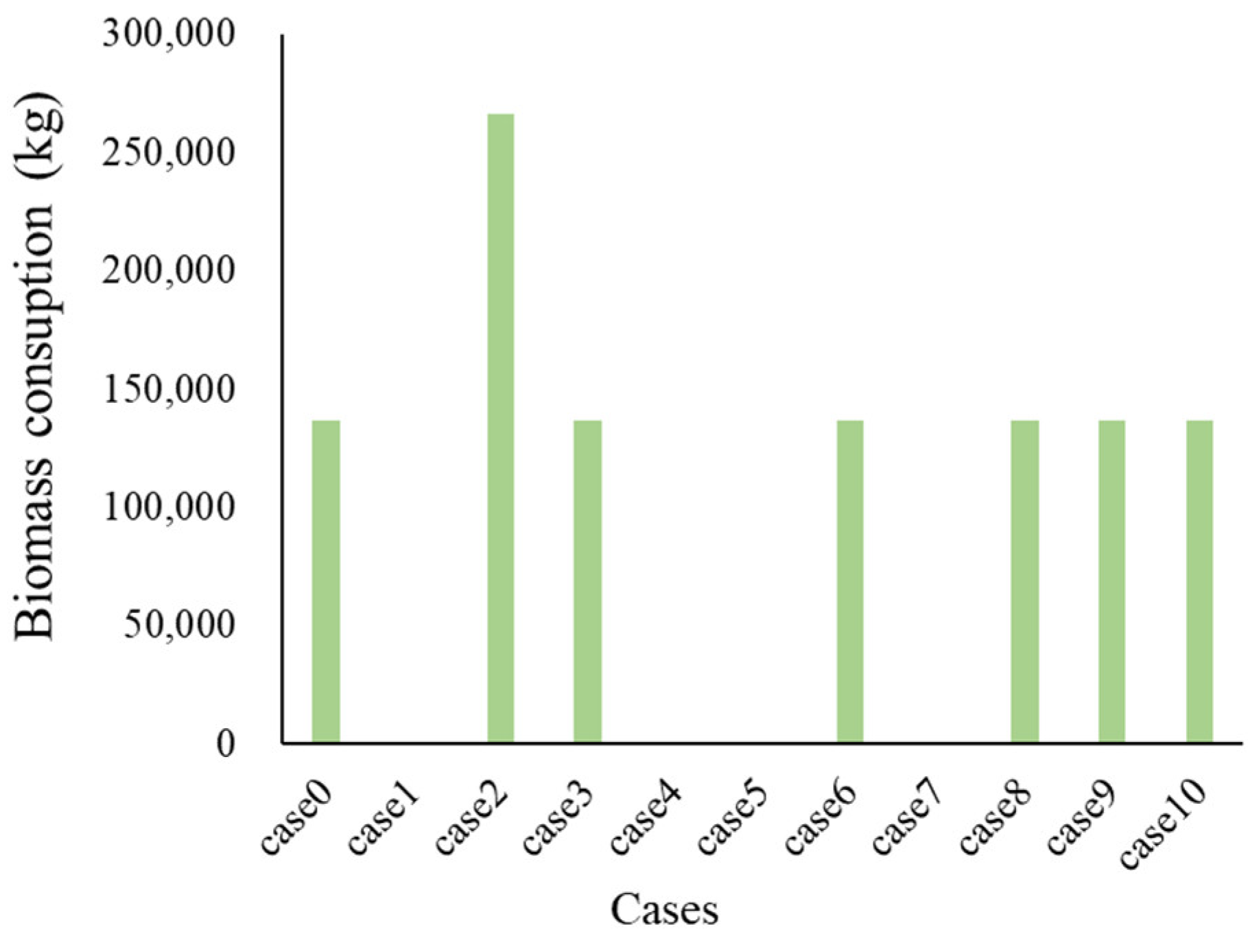
Figure 12 and
Figure 13 shows the power consumption and the biomass consumption, respectively. It is demonstrated that, generally, the biomass energy complements the electricity. Therefore, the biomass boiler usually can act as a good supplementary heating source for a coupling system.
4. Limitations
There are two main limitations in this work. The first one is that the calculation of heating loads is not precise. On the DeST or TRNSYS platform, the hour-by-hour heating load is calculated by discretizing time, and it can be seen from the load curve that the heating load oscillates violently, which is usually not the case. Because of the thermal inertia of the buildings, the heating-load curve should be relatively flat. However, this is supposed to have little effect on the accuracy of the simulation results, because the overall change trend of the heating load can still be reflected on the load curve. Furthermore, for the actual project in this case study, the difference between the actual operation results and the simulation results are not obvious. Therefore, the TRNSYS simulation is supposed be accurate enough for system design and optimization.
Moreover, for the proposed method, an obvious limitation is that the optimization of the system configuration is simplified. The optimization of a complementary heating system mainly includes three aspects, the system configuration, the operation strategy and the capacity of each piece of equipment. In this work, the system configuration is determined by setting a preliminary screening criterion for each potential piece of equipment, on the basis of the meteorological condition, resource abundance and the form of the buildings. Therefore, the system configuration in this work is not determined by using optimization algorithms. However, this simplification can greatly reduce the coupling degree of the optimization process, and a quick comparison of the potential schemes can be made by using the proposed method in this work.


 ,
, 


