Article

Design and Analysis of a Quad-Band Antenna for IoT and Wearable RFID Applications

1
Department of Electrical Engineering, HITEC University, Taxila 47080, Pakistan
2
Department of Biomedical Engineering, HITEC University, Taxila 47080, Pakistan
3
Department of Electrical Engineering, College of Engineering in Wadi Addawasir, Prince Sattam Bin Abdulaziz University, Wadi Addawasir 11991, Saudi Arabia
4
Department of Electrical Engineering, Faculty of Engineering & Technology, Gomal University, Dera Ismail Khan 29220, Pakistan
5
Biomedical Engineering Department, Balochistan University of Engineering and Technology (UET), Balochistan 89120, Pakistan
*
Author to whom correspondence should be addressed.
Electronics 2024, 13(4), 700; https://doi.org/10.3390/electronics13040700
Submission received: 23 December 2023 / Revised: 29 January 2024 / Accepted: 2 February 2024 / Published: 8 February 2024
(This article belongs to the Special Issue RF/Microwave Circuits for 5G and Beyond, Volume II)

Abstract

:
The role of antennas in wireless communication is critical for enabling efficient signal transmission and reception across various frequency bands, including those associated with IoT (Internet of Things), X-band, S-band, and RFID (radio-frequency identification) systems. This paper presents a small quadruple-band antenna with 25 × 40 × 1.5 mm3 dimensions designed for diverse wireless applications. It is adept at operating in the S-band (2.2 GHz), wireless local area network (WLAN) (5.7 GHz), microwave RFID frequency band (5.8 GHz), and X-band (7.7 GHz and 8.3 GHz). While the majority of existing research focuses on antennas covering two or three bands, our work stands out by achieving quad-band operation in the proposed antenna design. This antenna is constructed on a semiflexible Rogers RT5880 substrate, making it well-suited for wearable applications. Computer Simulation Technology (CST) Microwave studio (2019) simulation package software is chosen for design and analysis. The antenna design features a comb-shaped radiating structure, where each “tooth” is responsible for resonating at a distinct frequency with an appropriate bandwidth. The antenna retains stability in both free space and on-body wearability scenarios. It achieves a low specific absorption rate (SAR), meeting wearable criteria with SAR values below 1.6 W/Kg for all resonating frequencies. The proposed antenna demonstrates suitable radiation efficiency, reaching a maximum of 82.6% and a peak gain of 6.3 dBi. It exhibits a bidirectional pattern in the elevation plane and omnidirectional behavior in the azimuth plane. The antenna finds applications across multiple frequencies and shows close agreement between simulated and measured results, validating its effectiveness.

1. Introduction and Background

Wearable and flexible electronics have garnered significant interest across industrial and academic sectors, providing versatile applications for personal use, the Internet of Things (IoT), sports, military applications, RFID (radio-frequency identification), medical body area network (MBAN), and beyond [1,2]. A visual representation of these applications is depicted in Figure 1.
Lately, researchers have shown substantial interest in microstrip patch antennas for wearable devices due to their lightweight nature, simplicity in design, compact size, ease of fabrication, frequency tunability, and compatibility with planar circuits [3].
Conventional antenna designs, characterized by their stiffness and lack of flexibility, are considered unsuitable for wearable applications. Achieving conformability and comfortability becomes crucial in this regard. The effectiveness of antennas in terms of wearability and user mobility hinges on their passive nature, compact size, lightweight design, cost-effectiveness, and maintenance-free operation [4].
Diversifying substrate materials, including textiles, jeans, denim, polyfoam, PET, glass, conductive fabric polymers, felt, polyimide substrates, and cotton fabric, is instrumental in achieving flexibility and conformability. Numerous recent studies have adopted some of these substrates for conventional operating frequencies, such as 2.45 GHz [5,6,7,8]. However, it is noteworthy that certain designs within this frequency band may encounter limitations in data rates, accompanied by increased design complexity in specific cases.
Recent progress in wireless technology enables communication systems to achieve high data rates while simultaneously serving diverse applications. In this context, multiband antennas emerge as the optimal choice, aiming to attain high data rates by concentrating on specific frequency bands for effective radiation, guided by their stopband intervals [9]. The intricacy of this design process makes the development of multiband antennas more challenging compared to their single-band and UWB counterparts. Multiband antennas have been effectively employed in various applications, including RFID, IoT, WLAN, and satellite communications [10,11].
RFID (radio-frequency identification) technology finds widespread use in diverse applications such as healthcare, airports, libraries, the military, passports, and supply chain management for identification and tracking. Operating across multiple frequency bands, RFID includes low-frequency (LF) at 125 kHz for short-range applications, high-frequency (HF) at 13.56 MHz for smart cards and NFC, ultra-high-frequency (UHF) spanning 860–960 MHz for longer-range uses, microwave frequency (2.45 GHz) for active RFID in real-time location and industrial applications, and super-high-frequency (5.8 GHz) for specific high-data-transfer-rate needs. RFID frequency band selection is influenced by factors like required read range, application environment, and regulatory considerations, varying across regions, as reported in [12,13].
The Internet of Things (IoT) comprises an interconnected network of physical devices communicating through the internet, aiming to facilitate intelligent, seamless communication and automation among devices for increased efficiency and convenience. IoT applications span smart homes, wearable devices, industrial automation, healthcare monitoring, and smart cities. Operating frequency bands for IoT devices vary. Sub-1 GHz frequencies like 433 MHz and 868 MHz enable long-range, low-power communication (LPWAN); the 2.4 GHz band suits short-range communication with Zigbee and Bluetooth technologies; and 5.8 GHz is employed for higher data rates and shorter-range applications. Cellular networks, including LTE-M, NB-IoT, and 5G, operate in diverse bands for global IoT connectivity. Technologies like LoRa and Sigfox use various sub-1 GHz bands, providing long-range, low-power solutions for specific IoT applications. Recent efforts in IoT antenna design are explored in [14,15,16,17].
S-band and X-band, two segments of the microwave frequency spectrum, cater to various applications. S-band, typically ranging from 2 to 4 gigahertz (GHz), is prevalent in radar, satellite communication, and aerospace communication, offering a balanced compromise between signal propagation and data transfer rates. Meanwhile, X-band spans frequencies from 8 to 12 GHz, finding applications in weather and marine radar (around 9.3 GHz), airborne radar (around 10 GHz), satellite communication for uplink (7.25 to 7.75 GHz) and downlink (7.9 to 8.4 GHz), as well as deep space communication in space exploration (7.2 to 8.4 GHz). Both S-band and X-band play pivotal roles in various sectors, demonstrating versatility and reliability in radar and communication systems. Recent antenna developments associated with S-band and X-band communication are outlined in [18,19,20].
Wireless technology in the 5 GHz frequency range has versatile applications. Dedicated short-range communication (DSRC) and wireless access in vehicular environments (WAVE) utilize the 5.9 GHz band for vehicular-to-vehicular (V2V) and vehicle-to-infrastructure (V2I) communication, bolstering intelligent transportation systems. This enhances road safety, traffic efficiency, and overall transportation infrastructure, supporting the progress of connected and autonomous vehicles. Simultaneously, the 5 GHz band is a key spectrum for Wi-Fi networks, enabling high data rates and improved network performance through standards like 802.11a, 802.11n, 802.11ac, and 802.11ax (Wi-Fi 6). Recent developments in WLAN antenna design are detailed in [21,22,23].
In an effort to contribute to ongoing research, this paper reports the design and analysis of a wearable microstrip antenna featuring a comb-shaped structure with quad-band resonating capabilities at frequencies of 2.2 GHz, 5.7 GHz, 7.7 GHz, and 8.3 GHz suitable for S-band, WLAN, and X-band applications, respectively. Fabricated on a semiflexible Rogers RT5880 substrate, the antenna is well-suited for wearable applications, demonstrating favorable radiation patterns and commendable gain, efficiency, bandwidth, and reflection coefficient values. Moreover, assessing the SAR performance of the antenna is crucial for understanding wave–tissue interaction, a significant aspect in measuring antenna wearability. Subsequently, an analysis is conducted on a three-layered tissue phantom, yielding satisfactory results for the specified operating frequencies.
Table 1 offers a comprehensive and systematic analysis of multiband antennas, considering various resonant frequencies as documented in prior research endeavors. The categorization of the table is based on the configuration of antennas, specifically focusing on dual-band, tri-band, quad-band, and penta-band setups. Notably, the reported sizes of these antennas are meticulously compared to their actual sizes when operating at the lowest resonant frequency.
This analytical approach provides a valuable insight into the percentage reduction in size, as depicted in the final column of Table 1. This size reduction metric is crucial for evaluating the efficiency and practicality of multiband antennas, especially when considering their potential integration into wearable devices or other size-constrained applications.
Examining the content of Table 1, references [24,25,26] are representative of dual-band antennas. These antennas exhibit resonance primarily within the ISM band, coupled with additional frequencies at 4.9 GHz and 0.9 GHz. Notably, the substrate utilized in these designs is FR4, which, except for its application in polythylene foam, may not be the most suitable choice for wearability. Furthermore, the analysis indicates that these dual-band antennas achieve less than a 50% reduction in size, raising considerations about their practicality in size-sensitive applications.
It is important to acknowledge that dual-band antennas, as highlighted in the table, are characterized by their limited applicability, as they are designed to operate within two specified frequency bands. This inherent limitation renders them less suitable and less in demand for addressing the diverse and evolving requirements of the contemporary wireless communication era.
Next, the studies in references [27,28,29,30] showcase tri-band antennas employing FR4 and Rogers RO4350 substrates. Despite the flexibility limitations associated with FR4, it is a common choice. These tri-band antennas are specifically designed for operations in ISM, WLAN, LTE, and 5G applications. The proposed designs reduced size by 41.3%, 60%, and 36%, respectively, and showed well-optimized dimensions. Nevertheless, when considering the number of resonance bands, their effectiveness may not be as favorable when compared to quadband antennas.
Shifting the focus to the next category, quad-band antennas [31,32,33,34,35,36,37] are highlighted in the provided table. Among them, three quad-band antennas were fabricated using an FR4-based substrate, while the rest were constructed on substrates such as Rogers, polyester, and felt. These antennas are versatile and suitable for wearable applications, serving purposes such as LTE, WBAN, RFID, ISM, 5G, S-band, C-band, UHF, Ku-band, and X-band, each corresponding to the specific substrate used. Notably, our proposed antenna design has achieved a more significant size reduction of 56.49% compared to the designs presented in the existing literature.
Moving towards the last category of the table in comparison, penta-band antennas [38,39,40] were examined, catering to a broad spectrum of applications including WLAN, ISM, the lower band of 5G, X-band, and C-band. Notably, all of these antennas were designed using an FR4-based substrate material, restricting their usage to wearable applications. It is evident that these antennas exhibit a lower percentage of size reduction when compared to the antenna proposed in this paper.

2. Method and Materials

The design and analysis were conducted using the CST simulation package, implementing a semiflexible Roger RT5880 substrate (Rogers Corp., Chandler, AZ, USA) with a relative permittivity value of 2.2 and a dielectric loss tangent of 0.0009. Roger RT 5880 offers various advantages, including the lowest electrical loss, minimal moisture absorption, isotropic properties, uniform electrical characteristics across a broad frequency range, and excellent chemical resistance. Its suitability for wearable devices is particularly relevant in the current era of IoT applications, where flexibility is in high demand. Additionally, recent work on flexible RFID tags has recommended Roger RT 5880 for its ease of fabrication and relatively stable bending properties [41]. The thickness of the radiating patch is selected to be 0.02 mm. The design’s unique characteristic is the integration of comb-shaped slots within the rectangular patch. The preliminary design details of the rectangular patch are discussed below.

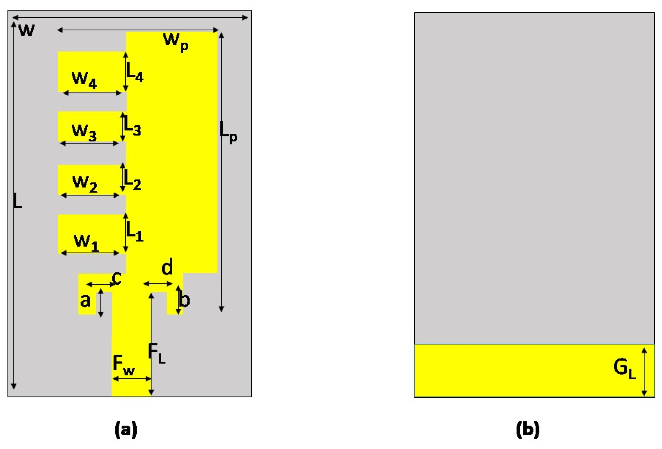
2.1. Initiating Antenna Design: An Overview of Preliminary Calculations and Considerations

When utilizing the transmission line model for antenna design, one can establish the dimensions of the antenna, particularly the length ( L P ) and width ( W P ) of the radiating patch, through the following relationships [42,43]:
W P = v o 2 f r 2 ε r + 1
L P = v o 2 f r ε r e f f 2 Δ L
To calculate the effective permittivity ε r e f f of the substrate, the following equation is utilized:
ε r e f f = ε r + 1 2 + ε r 1 2 1 + 10 h s W P
Subsequently, using the provided equation, we determine the extent to which the patch needs to be reduced:
Δ L = ( 0.412 h s ) ( ε r e f f + 0.3 ) ( W P h s + 0.264 ) ( ε r e f f 0.258 ) ( W P h s + 0.8 )
In the given context, f r represents the operating frequency, ε r is the dielectric constant of the substrate, v o is the speed of light, ε r e f f is the effective dielectric constant of the substrate, accounting for the fringing effect, h s is the thickness of the substrate, and Δ L denotes the extension of length. This extension can be incorporated into Equation (2) to achieve the actual length of the antenna.
The dimensions of the ground plane can be determined using the following expressions:
L g = L p + 6 × h s
W g = W p + 6 × h s

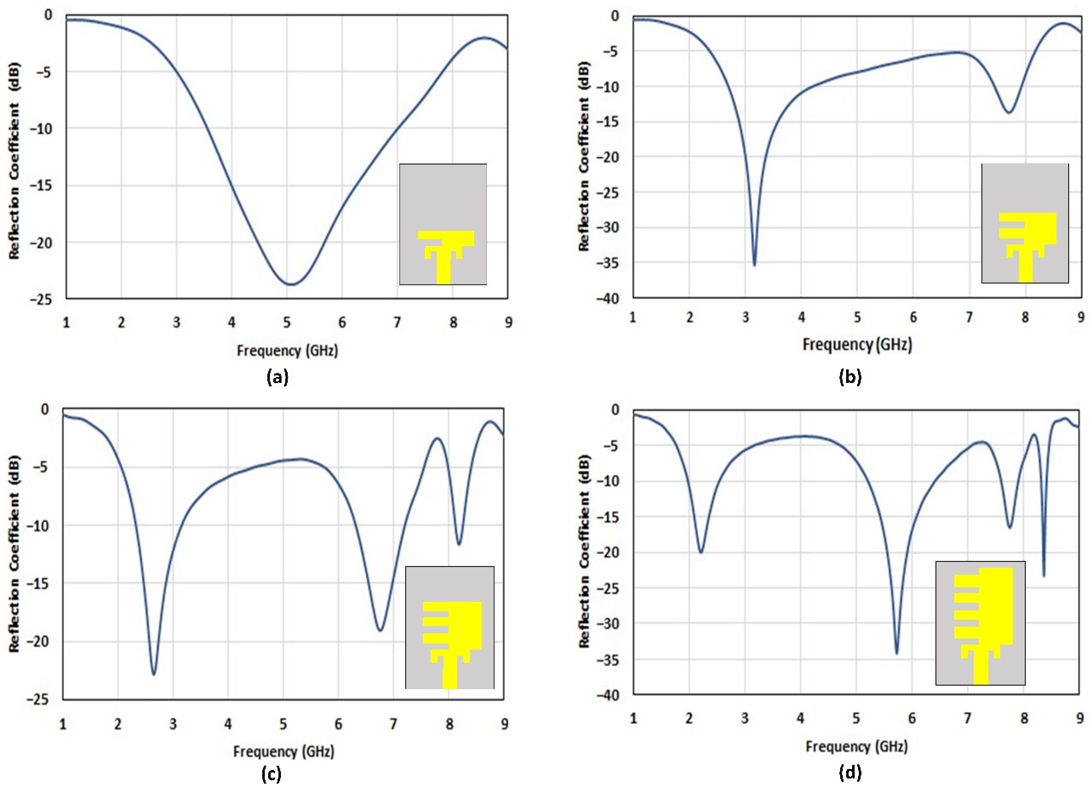
2.2. Evolutionary Design Progression of the Proposed Antenna

Miniaturization is of great significance in antenna design. This process focuses on reducing the antenna’s physical size, minimizing footprint, optimizing cost-effectiveness, and improving comfort for biomedical applications [44].
Typically, the antenna length is half of the resonant frequency’s wavelength. For instance, at a resonance frequency of 1 GHz, the physical length of an antenna would ideally be 100 mm. However, this length can be impractical for deployment in wearable and RFID applications where antenna footprint is a crucial consideration [45].
Various techniques can be employed to miniaturize a microstrip patch antenna, including the addition of slots, shorting pins, loading material, fractal geometry [29], high-permittivity substrates, pin shorting techniques, and the utilization of metamaterial [46,47,48,49]. These approaches primarily extend the current flow through longer paths, effectively increasing the electrical length of the antenna while concurrently minimizing its physical dimensions. In alignment with this strategy, we chose comb-shaped slots in a conventional rectangular patch to achieve miniaturization.
Leveraging the mathematical framework outlined in Section 3.1, a standard rectangular patch antenna resonating at 2.2 GHz can be formulated, yielding dimensions of 45.18 × 53.87 × 1.5 mm3, as depicted in Figure 2.
To minimize the patch size, a comb-based slotting strategy is incrementally introduced, as illustrated in Figure 3a–d. This figure showcases the progressive design evolution of the proposed antenna, illustrating the contribution of each “tooth” in the radiating patch to achieve distinct frequency bands. Initially, the antenna’s radiating patch features a single tooth, resulting in a single-band resonance at 5.0 GHz.
This is depicted in Figure 3a. Subsequent modifications introduce a second tooth, leading to dual-band characteristics at 3.1 GHz and 7.7 GHz, as depicted in Figure 3b. The addition of a third tooth results in three distinct bands, as shown in Figure 3c. By incorporating an additional tooth, a quad-band resonating characteristic at 8.3 GHz is achieved, as illustrated in Figure 3d.
The adoption of a comb-based slotting strategy successfully reduces the size of the antenna to 25 × 40 × 1.5 mm3. This leads to a notable decrease in antenna size, approximately 56.49%, accompanied by the additional benefit of quad-band resonance.
The antenna produces a reflection coefficient consistently below −10 dB, indicating effective impedance matching, as depicted in Figure 3. The achieved quadruple bands showcase favorable impedance matching characteristics, resulting in bandwidths of 0.554 GHz (1.990–2.544 GHz), 1.188 GHz (5.217–6.405 GHz), 0.316 GHz (7.584–7.901 GHz), and 0.108 GHz (8.306–8.415 GHz), respectively.

2.3. Optimization of the Design

The optimization of the antenna geometry aims to achieve optimal radiating performance by fine-tuning the dimensions of the patch, substrate, and feedline while ensuring consistent quad-band resonant frequencies. Optimization is achieved by utilizing the inbuilt tool in the CST Microwave studio simulation package 2019. The geometry of the optimized antenna is illustrated in Figure 4a, and a modified ground plane is presented in Figure 4b. The optimized values for the feed line (FL), feed width (Fw), and other dimensions, including the teeth and inset feed, are detailed in Table 2.

3. Analysis of the Experimental and Simulated Outcomes

After performing the numerical simulation of the proposed design, an optimized antenna prototype is fabricated using a semiflexible substrate called Rogers RT5880. The resulting prototype is then tested to confirm the simulated results’ accuracy. Figure 5 presents the top view of the fabricated antenna prototype. This antenna connects through a microstrip feedline and utilizes a Sub-Miniature Version A (SMA) connector. SMA connectors are widely chosen for patch antennas operating at various frequencies due to their versatility in RF applications and their established reputation for dependable performance across different frequency bands.

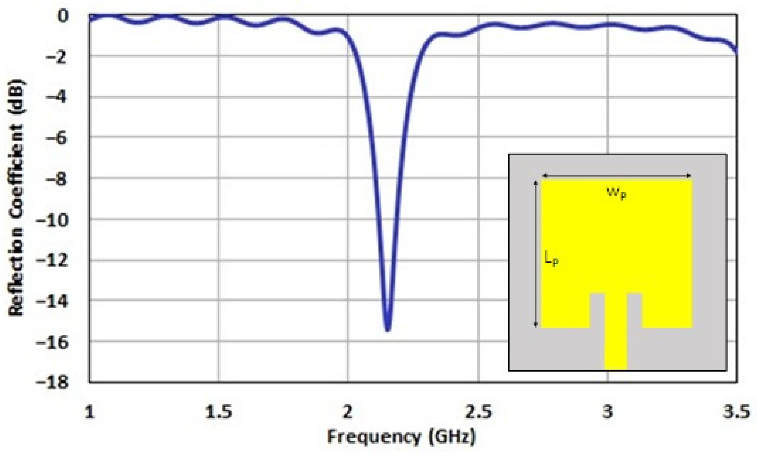
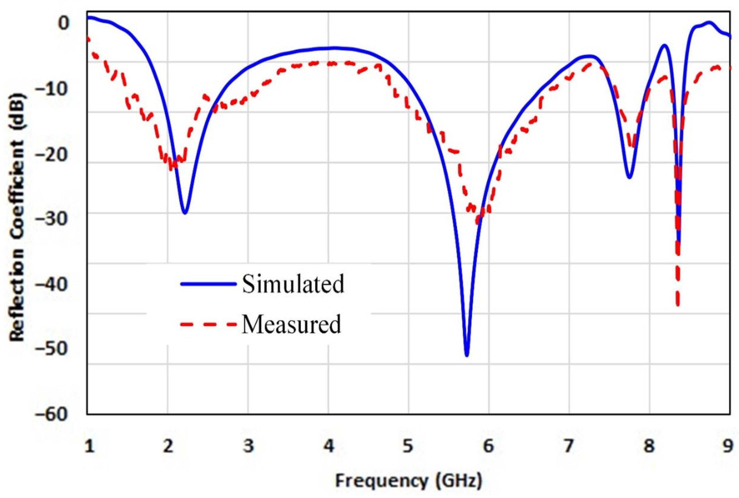
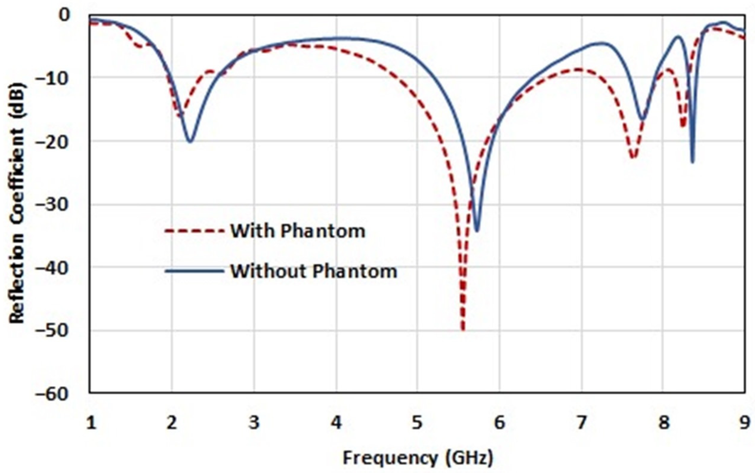
3.1. Reflection Coefficient

Figure 6 presents a comparison between the measured and calculated reflection coefficient results. The analysis reveals a close alignment between the calculated and measured return loss, consistently maintaining values well below −10 dB. The minor frequency variation observed may be attributed to slight discrepancies in the fabrication of the prototype antenna design. Additionally, factors such as the soldering process and temperature fluctuations during the connection of the SMA connector to the antenna could subtly influence the measured results.

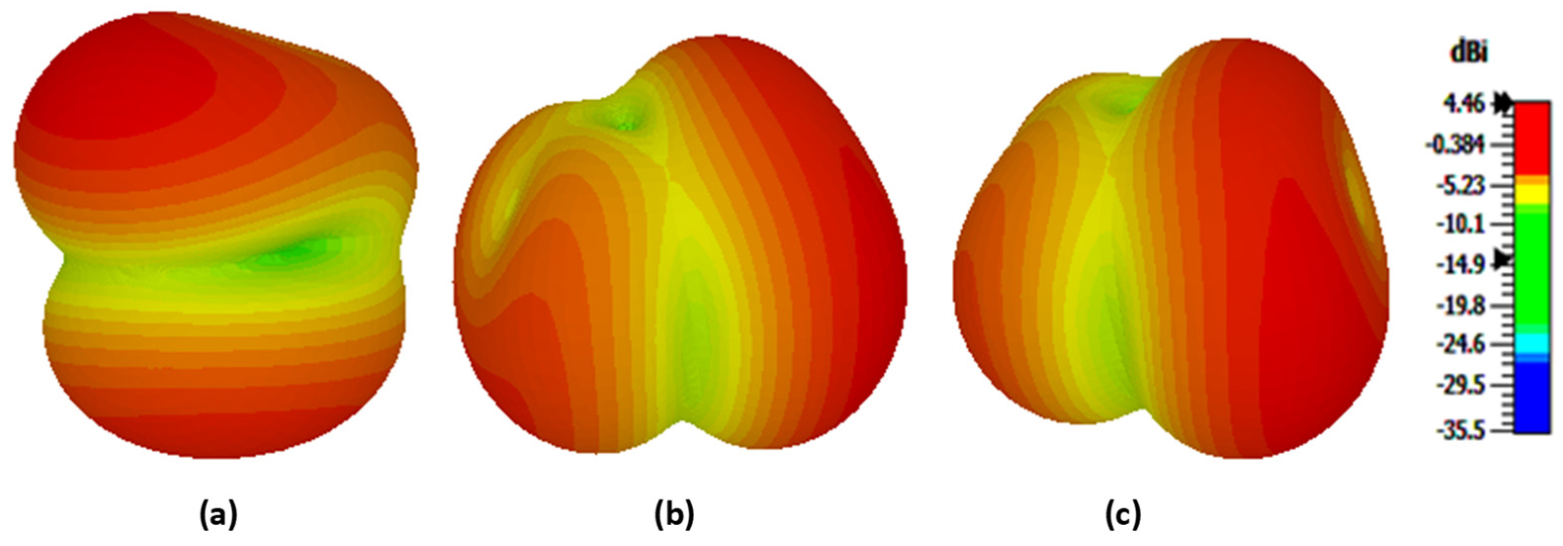
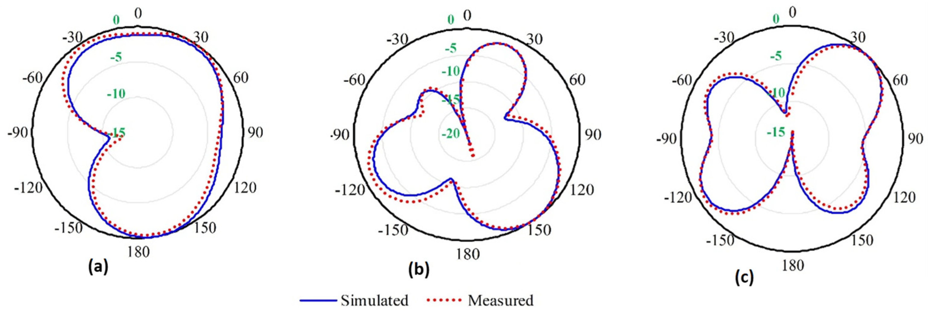
3.2. Radiation Pattern (3-D and 2-D)

Figure 7 illustrates the simulated 3-D radiation pattern of the proposed antenna at 5.7 GHz, encompassing both azimuth (φ = 0°) and elevation (φ = 90°) planes. The corresponding 2-D results are presented in Figure 8. The visualization reveals that the antenna in the E-plane (φ = 0°) exhibits enhanced directionality compared to the H-plane (φ = 90°). Moreover, bidirectionality is evident when θ = 90°. The figure underscores the close agreement between the simulated and measured results, ensuring the reliability of the antenna’s performance characterization. Furthermore, the observed correlation between the 3-D and 2-D radiation patterns is evident, providing additional validation for the analysis.

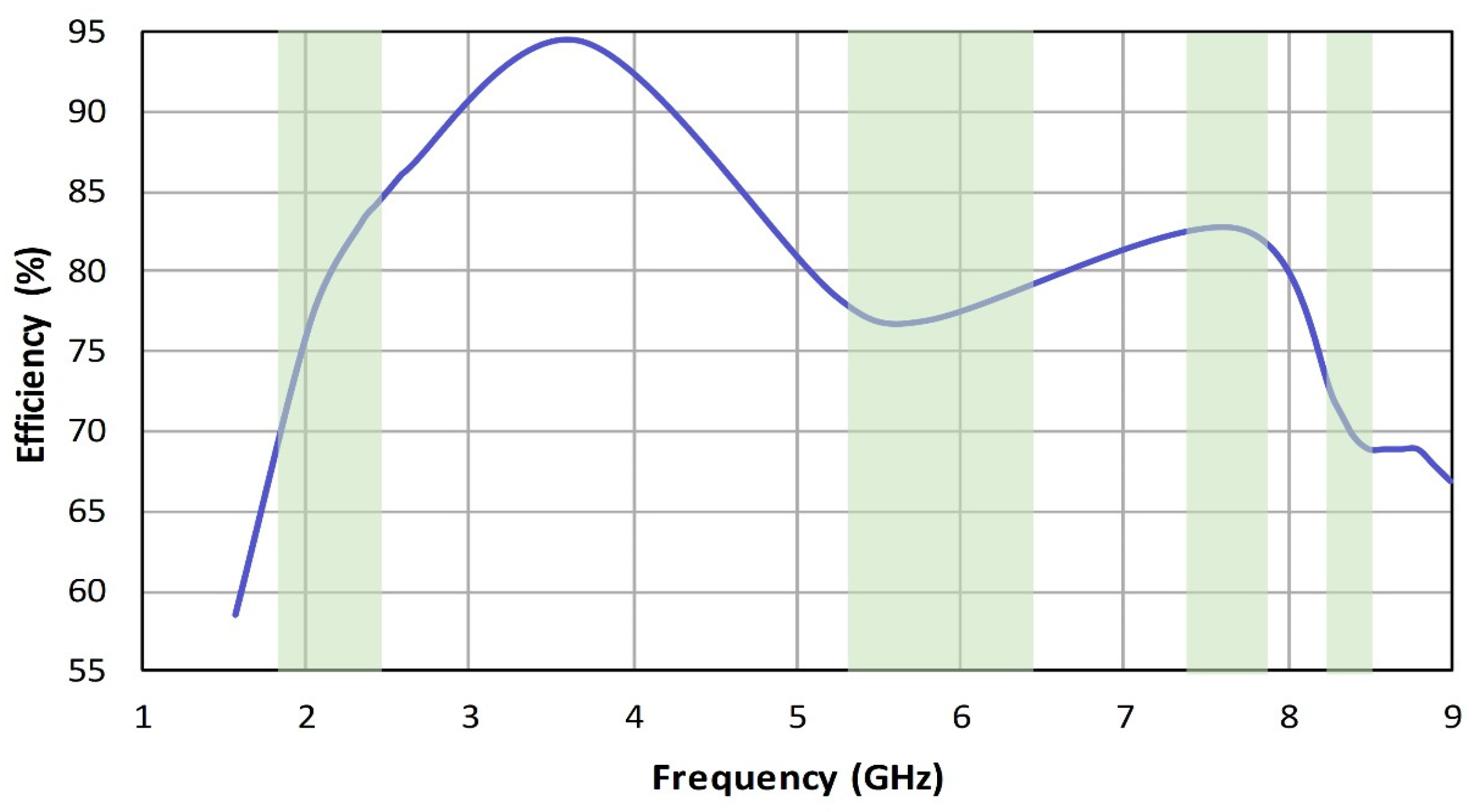
3.3. Efficiency and Gain

The antenna efficiency indicates how effectively input power is converted into radiated electromagnetic energy. It signifies the antenna’s ability to function with minimal losses, providing insight into its overall performance in capturing and radiating electromagnetic waves. Higher efficiency implies that a larger portion of the input power is effectively utilized for signal transmission or reception, while lower efficiency suggests a greater proportion of power is lost as heat or in other non-radiative forms. Efficient antennas are crucial for optimizing communication systems, ensuring reliable signal transmission, and minimizing energy waste. Figure 9 illustrates the quantification of antenna efficiency, showcasing corresponding values of 82.5%, 77%, 82%, and 70% at 2.2, 5.7, 7.7, and 8.3 GHz, respectively.
Antenna gain represents the measure of how well an antenna focuses its radiated power in a specific direction. A higher gain indicates more effective signal transmission or reception in the desired direction, which is particularly important in communication systems where signal strength and directionality play a crucial role. The antenna’s attained gain is depicted in Figure 10. The figure clearly indicates that the antenna demonstrates gains of 1.4 dBi and 3.3 dBi at 2.2 GHz and 5.7 GHz, respectively. Notably, the peak gain reaches 6.3 dBi at 7.7 GHz, while 8.3 GHz yields a gain of 3.5 dBi.

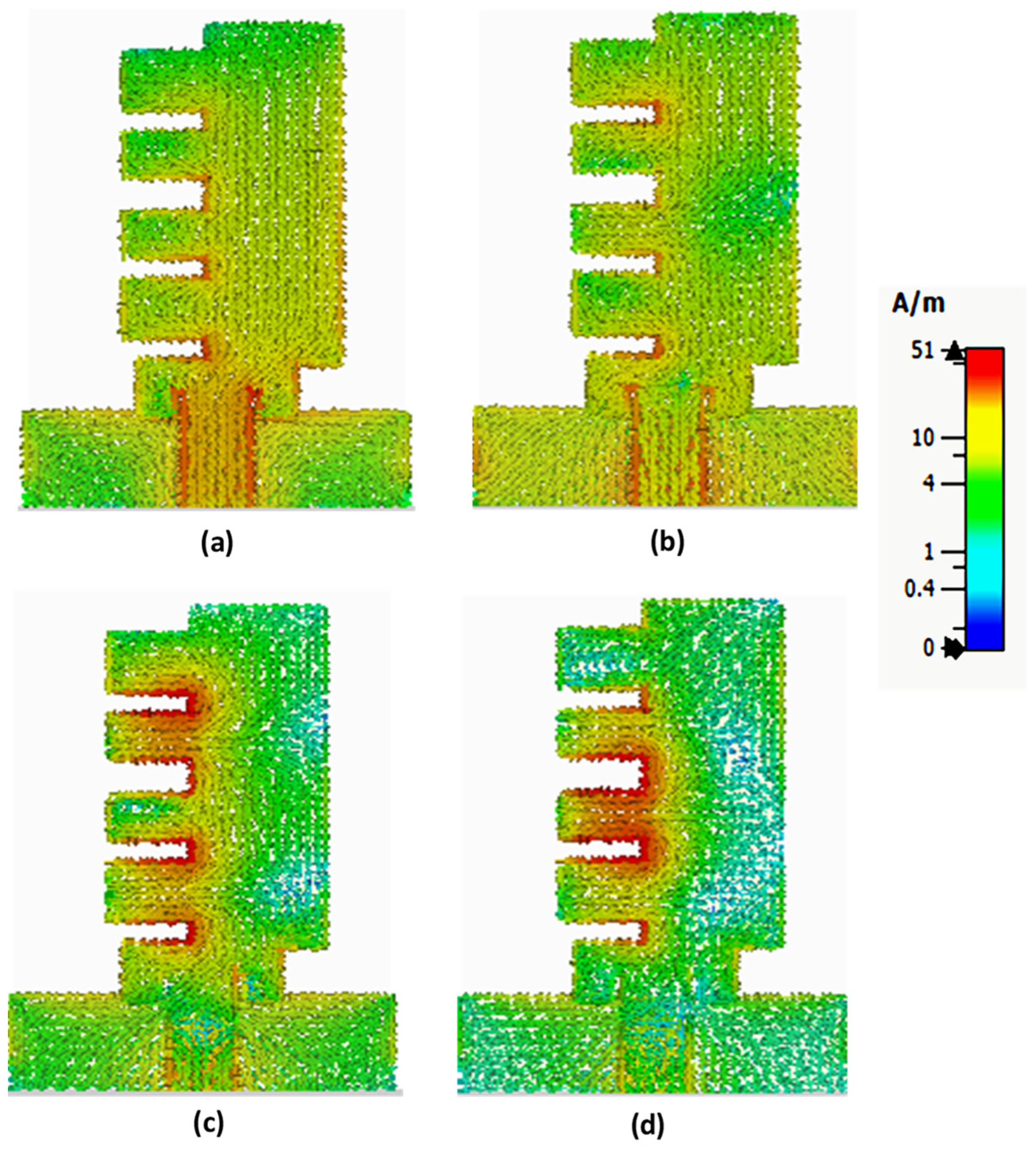
3.4. Surface Current Distribution

The resonance condition results in optimal energy transfer between the antenna and the surrounding space. The surface current distribution, which represents the flow of electric current across the antenna structure, is a key factor in achieving resonance. In Figure 11, the depicted surface current distribution across resonant bands provides insight into how the current flows on the antenna structure during different operating frequencies. This variation in surface current contributes to the antenna’s ability to efficiently resonate and perform effectively across multiple frequency bands when the same excitation is maintained at the input port.
In the instance of lower frequencies, like 2.2 and 5.7 GHz, the antenna facilitates the current to travel along a lengthier path around the periphery, as illustrated in Figure 11a,b. Noticeably, as we move towards higher-frequency bands, a distinct rise in current concentration is observed at the center of the antenna. This is due to the skin effect at high frequencies, causing the current density to be confined to the edges of the teeth, as depicted in Figure 11c,d. Moreover, as the current distribution becomes concentrated in a smaller space at higher frequencies, the antenna manifests a compact size, providing additional evidence that smaller antennas tend to yield higher resonant frequencies.
Furthermore, the resonant frequency can be deduced from the path covered by the surface current on the radiating patch. In the ideal scenario, the antenna resonates at half wavelength. In the case of a printed antenna, it is estimated that the antenna radiates equally in the substrate medium and air. Therefore, the effective resonant frequency of the antenna can be formulated as the following:
f r = c 2 × L × ϵ r + c 2 × L × 10 3
Here, f r represents the resonant frequency, L is the length of the radiating patch, c is the speed of light, and ϵ r is the relative permittivity of the substrate material.
For instance, considering the resonant frequency of 8.3 GHz, the location of the maximum surface current in Figure 11d aligns with the inner tooth of the patch. With a calculated length of 22 mm (4 × 5.5 mm), the resonant frequency f r can be computed using Equation (7) as 8.19 GHz, closely approximating the actual frequency of 8.3 GHz.

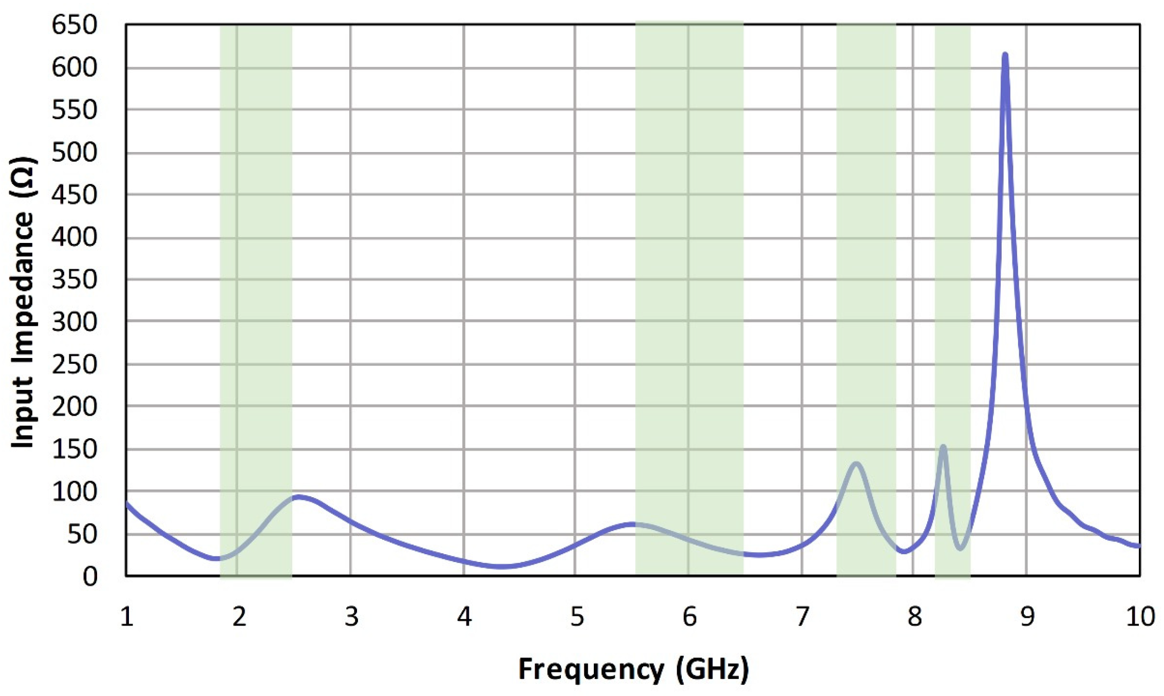
3.5. Input Impedance
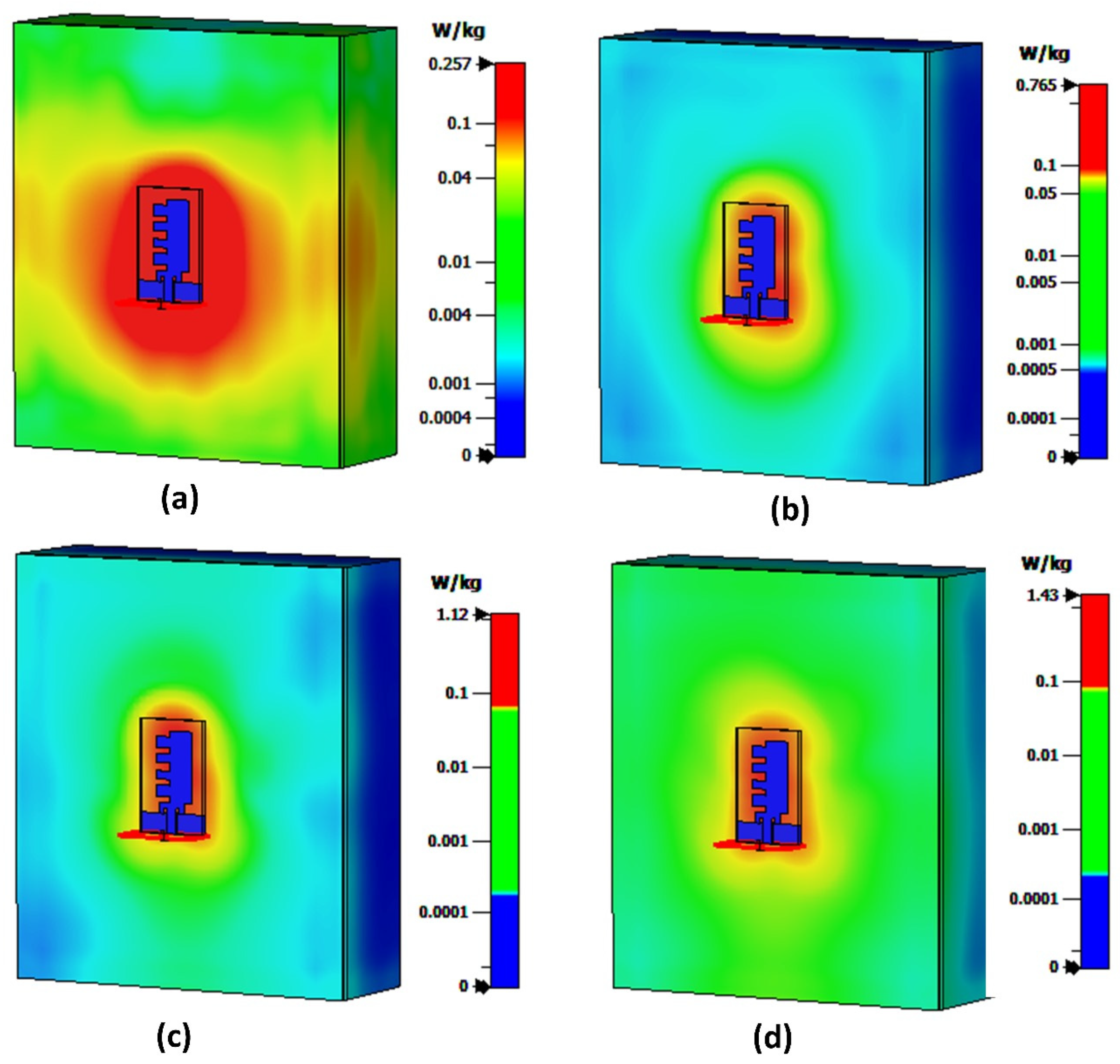
The antenna displays impedance variation across different bands; nonetheless, upon closer examination, this fluctuation remains within the 50-ohm range, affirming satisfactory matching characteristics. Figure 12 visually represents this finding.

4. SAR Analysis

Analysis of SAR is imperative for wearable devices to monitor the extent of energy absorption by the contacting tissue.
S A R = σ E 2 2 ρ
Equation (8) quantifies SAR in W/Kg, where E represents the electric field vector (V/m), σ (S/m) is the effective conductivity, and ρ is the density of the tissue layers, with thickness values of 40 mm for muscle, 2 mm for fat, and 1 mm for skin, and respective densities of 1020 kg/m3, 909 kg/m3, and 1060 kg/m3. The dielectric properties of these layers were defined using the second-order Debye’s model for dispersion fitting, as detailed in Table 3 [50].
Figure 13 illustrates the comparison of the antenna’s reflection coefficient in free space and when mounted on a tissue phantom. The results exhibit a close agreement with each other. The observed minor drift is quite expected, as antennas tend to behave differently when loaded by a dispersive medium such as a tissue phantom. This behavior is reflected in the observed drift in the reflection coefficient, as evident in Figure 13.
Figure 14 illustrates the simulation outcomes for SAR1g at resonance frequencies. The phantom’s dimensions are 130 × 150 × 53 mm3, with the antenna 3 mm from the top skin layer. An 8-mW input power was applied. The Federal Communication Commission (FCC) has set a SAR1g threshold of 1.6 W/Kg. Results indicate that, at each operating frequency (2.2, 5.7, 7.7, and 8.3 GHz), the antenna maintains values of 0.257, 0.765, 1.12, and 1.43 W/Kg, respectively, all well below the allowable limit.

5. Conclusions and Future Work

This study involves designing and analyzing a quad-band wearable antenna using the CST simulation package. The antenna achieves miniaturization through a comb-shaped slotting strategy, ensuring good impedance matching and appropriate bandwidths at resonant frequencies suitable for S-band, WLAN, and X-band applications. This study includes numerical quantification and, where feasible, experimental measurements of various performance characteristics such as the radiation pattern, reflection coefficient, efficiency, and gain. The simulated and measured results show close agreement, indicating stability in antenna performance. Surface current density maps illustrate the currents’ paths at lower and higher frequencies. Phantom modeling is utilized to assess wearability, and SAR analysis is performed to quantify heat generation due to tissue–wave interaction at all resonant frequencies, ensuring compliance with the allowable threshold level of 1.6 W/Kg.
In future work, the emphasis will be on improving the antenna’s wearability by exploring highly flexible substrate materials like polyfoam, jeans, or denim. Adopting a fractal-type design can contribute to miniaturization. To increase gain, options such as a multi-element array configuration can be considered. Another possibility involves configuring the current antenna as MIMO (multiple input, multiple output), potentially boosting data throughput and reliability. These future endeavors aim to advance the antenna’s overall performance, wearability, and functionality through the use of innovative substrate materials, intricate designs, and advanced configurations.

Author Contributions

Conceptualization, N.N.-U. and W.M.A.; Data curation, W.A.; Formal analysis, W.A., N.N.-U., W.M.A., A.M., A.H., J.A.N. and M.A.K.; funding acquisition, W.M.A.; investigation, N.N.-U. and W.M.A.; methodology, W.A., N.N.-U., W.M.A., A.M., A.H., J.A.N. and M.A.K.; project administration, N.N.-U. and W.M.A.; resources, W.M.A.; software, W.A. and N.N.-U.; supervision, N.N.-U. and W.M.A.; validation, N.N.-U. and W.M.A.; visualization, W.A., N.N.-U., W.M.A., A.M. and A.H.; writing—original draft, W.A., A.M. and A.H.; writing—review and editing, W.A., N.N.-U. and W.M.A. All authors have read and agreed to the published version of the manuscript.

Funding

This study is supported from Prince Sattam bin Abdulaziz University.

Data Availability Statement

Data is contained within the article.

Acknowledgments

This study is supported via funding from Prince Sattam bin Abdulaziz University project number (PSAU/2024/R/1445).

Conflicts of Interest

The authors declare no conflicts of interest.

References

  1. Awan, W.A.; Abbas, A.; Naqvi, S.I.; Elkamchouchi, D.H.; Aslam, M.; Hussain, N. A Conformal Tri-Band Antenna for Flexible Devices and Body-Centric Wireless Communications. Micromachines 2023, 14, 1842. [Google Scholar] [CrossRef]
  2. Sabban, A. Wearable Circular Polarized Antennas for Health Care, 5G, Energy Harvesting, and IoT Systems. Electronics 2022, 11, 427. [Google Scholar] [CrossRef]
  3. Sharma, M. Design and analysis of multiband antenna for wireless communication. Wirel. Pers. Commun. 2020, 114, 1389–1402. [Google Scholar] [CrossRef]
  4. Hashim, F.F.; Mahadi, W.N.L.B.; Abdul Latef, T.B.; Othman, M.B. Key Factors in the Implementation of Wearable Antennas for WBNs and ISM Applications: A Review WBNs and ISM Applications: A Review. Electronics 2022, 11, 2470. [Google Scholar] [CrossRef]
  5. Hashim, F.F.; Mahadi, W.N.L.B.W.; Abdul Latef, T.B.; Othman, M.B. Fabric–Metal Barrier for Low Specific Absorption Rate and Wide-Band Felt Substrate Antenna for Medical and 5G Applications. Electronics 2023, 12, 2754. [Google Scholar] [CrossRef]
  6. Cui, J.; Liu, F.X.; Shen, X.; Zhao, L.; Yin, H. Textile Bandwidth-Enhanced Coupled-Mode Substrate-Integrated Cavity Antenna with Slot. Electronics 2022, 11, 2454. [Google Scholar] [CrossRef]
  7. Azeez, H.I.; Yang, H.-C.; Chen, W.-S. Wearable Triband E-Shaped Dipole Antenna with Low SAR for IoT Applications. Electronics 2019, 8, 665. [Google Scholar] [CrossRef]
  8. Yadav, A.; Singh, V.K.; Yadav, P.; Beliya, A.K.; Bhoi, A.K.; Barsocchi, P. Design of Circularly Polarized Triple-Band Wearable Textile Antenna with Safe Low SAR for Human Health. Electronics 2020, 9, 1366. [Google Scholar] [CrossRef]
  9. Dey, A.B.; Mitra, D.; Arif, W. Design of CPW fed multiband antenna for wearable wireless body area network applications. Int. J. RF Microw. Comput. Eng. 2020, 30, e22459. [Google Scholar] [CrossRef]
  10. Li, Q.; Fang, J.; Ding, J.; Cao, W.; Sun, J.; Guo, C.; Liu, T. A Novel Tuning Fork-Shaped Tri-Band Planar Antenna for Wireless Applications. Electronics 2023, 12, 1081. [Google Scholar] [CrossRef]
  11. Abdulzahra, D.H.; Alnahwi, F.; Abdullah, A.S.; Al-Yasir, Y.I.A.; Abd-Alhameed, R.A. A Miniaturized Triple-Band Antenna Based on Square Split Ring for IoT Applications. Electronics 2022, 11, 2818. [Google Scholar] [CrossRef]
  12. Colaco, J.; Lohani, R. Multi-band Microstrip Square Patch Antenna Design for IoT based RFID technology and its various applications. In Proceedings of the 2021 6th International Conference for Convergence in Technology (I2CT), Maharashtra, India, 2–4 April 2021; IEEE: Piscataway, NJ, USA, 2021. [Google Scholar]
  13. Abdulkawi, W.M.; Nizam-Uddin, N.; Sheta, A.F.A.; Elshafiey, I.; Al-Shaalan, A.M. Towards an efficient chipless RFID system for modern applications in IoT networks. Appl. Sci. 2021, 11, 8948. [Google Scholar] [CrossRef]
  14. Li, E.; Li, X.J.; Seet, B.-C. A Triband Slot Patch Antenna for Conformal and Wearable Applications. Electronics 2021, 10, 3155. [Google Scholar] [CrossRef]
  15. Abdulkawi, W.M.; Sheta, A.F.A.; Elshafiey, I.; Alkanhal, M.A. Design of Low-Profile Single- and Dual-Band Antennas for IoT Applications. Electronics 2021, 10, 2766. [Google Scholar] [CrossRef]
  16. Al Ka’bi, A. A Proposed Antenna Design for IoT and 5G-WiFi Applications. Telecommun. Radio Eng. 2022, 81, 15–22. [Google Scholar]
  17. Patnaik, A.; Kartikeyan, M.V. Compact dual and triple band antennas for 5G-IOT applications. Int. J. Microw. Wirel. Technol. 2022, 14, 115–122. [Google Scholar]
  18. Kabir, S.S.; Khan, M.H.; Latif, S.I. A Multi-Band Circularly Polarized-Shared Aperture Antenna for Space Applications at S and X Bands. Electronics 2023, 12, 4439. [Google Scholar] [CrossRef]
  19. Rotshild, D.; Abramovich, A. Ultra-Wideband Reconfigurable X-Band and Ku-Band Metasurface Beam-Steerable Reflector for Satellite Communications. Electronics 2021, 10, 2165. [Google Scholar] [CrossRef]
  20. Mahendran, K.; Gayathri, R.; Sudarsan, H. Design of multi band triangular microstrip patch antenna with triangular split ring resonator for S band, C band and X band applications. Microprocess. Microsyst. 2021, 80, 103400. [Google Scholar] [CrossRef]
  21. Chung, M.-A.; Yang, C.-W. Miniaturized Broadband-Multiband Planar Monopole Antenna in Autonomous Vehicles Communication System Device. Electronics 2021, 10, 2715. [Google Scholar] [CrossRef]
  22. Khan, Z.; Memon, M.H.; Rahman, S.U.; Sajjad, M.; Lin, F.; Sun, L.J.S. A single-fed multiband antenna for WLAN and 5G applications. Sensors 2020, 20, 6332. [Google Scholar] [CrossRef] [PubMed]
  23. Mohammad Saadh, A.W.; Khangarot, S.; Sravan, B.V.; Aluru, N.; Ramaswamy, P.; Ali, T.; Pai, M.M. A compact four-element MIMO antenna for WLAN/WiMAX/satellite applications. Int. J. Commun. Syst. 2020, 33, e4506. [Google Scholar] [CrossRef]
  24. Hussain, M.B.; Butt, M.; Nadeem, Z.; Zahid, M.; Amin, Y. Design of Dual-Band Microstrip Patch Antenna for Wireless Local Area Network Applications. Eng. Proc. 2023, 46, 3. [Google Scholar]
  25. Najumunnisa, M.; Sastry, A.S.C.; Madhav, B.T.P.; Das, S.; Hussain, N.; Ali, S.S.; Aslam, M. A Metamaterial Inspired AMC Backed Dual Band Antenna for ISM and RFID Applications. Sensors 2022, 22, 8065. [Google Scholar] [CrossRef] [PubMed]
  26. Ahmad, A.; Faisal, F.; Ullah, S.; Choi, D.-Y. Design and SAR analysis of a dual band wearable antenna for WLAN applications. Appl. Sci. 2022, 12, 9218. [Google Scholar] [CrossRef]
  27. Karthikeyan, M.; Sitharthan, R.; Ali, T.; Roy, B. Compact multiband CPW fed monopole antenna with square ring and T-shaped strips. Microw. Opt. Technol. Lett. 2020, 62, 926–932. [Google Scholar] [CrossRef]
  28. Jha, P.; Kumar, A.; De, A.; Jain, R.K. CPW-fed metamaterial inspired compact multiband antenna for LTE/5G/WLAN communication. Frequenz 2022, 76, 401–407. [Google Scholar] [CrossRef]
  29. Wang, L.; Yu, J.; Xie, T.; Bi, K. A novel multiband fractal antenna for wireless application. Int. J. Antennas Propag. 2021, 2021, 9926753. [Google Scholar] [CrossRef]
  30. Li, R.; Wu, C.; Sun, X.; Zhao, Y.; Luo, W. An EBG-based triple-band wearable antenna for WBAN applications. Micromachines 2022, 13, 1938. [Google Scholar] [CrossRef]
  31. Kumar, A.; Pharwaha, A.P.S. Development of a modified Hilbert curve fractal antenna for multiband applications. IETE J. Res. 2022, 68, 3597–3606. [Google Scholar] [CrossRef]
  32. Thiruvenkadam, S.; Parthasarathy, E. Compact multiband monopole antenna design for IoT applications. J. Electromagn. Waves Appl. 2023, 37, 629–643. [Google Scholar] [CrossRef]
  33. Karthik, V.; Rao, T.R. Performance investigations of a quad-band microstrip antenna for body wearable wireless devices. Appl. Comput. Electromagn. Soc. J. (ACES) 2021, 36, 980–988. [Google Scholar] [CrossRef]
  34. Mandal, D.; Pattnaik, S.S. Quad-band wearable slot antenna with low SAR values for 1.8 GHz DCS, 2.4 GHz WLAN and 3.6/5.5 GHz WiMAX applications. Prog. Electromagn. Res. B 2018, 81, 163–182. [Google Scholar] [CrossRef]
  35. Elias, B.B.Q.; Soh, P.J.; Al-Hadi, A.A.; Joshi, R.; Li, Y.; Podilchak, S.K. Design of a quad band CPW-fed compact flexible patch antenna for wearable applications. In Proceedings of the 2020 14th European Conference on Antennas and Propagation (EuCAP), Copenhagen, Denmark, 15–20 March 2020; IEEE: Piscataway, NJ, USA, 2020. [Google Scholar]
  36. Ali, T.; Aw, M.S.; Biradar, R.C. A fractal quad-band antenna loaded with L-shaped slot and metamaterial for wireless applications. Int. J. Microw. Wirel. Technol. 2018, 10, 826–834. [Google Scholar] [CrossRef]
  37. Mohamed, H.A.; Sultan, K. Quad band monopole antenna for IoT applications. In Proceedings of the 2018 IEEE International Symposium on Antennas and Propagation & USNC/URSI National Radio Science Meeting, Boston, MA, USA, 8–13 July 2018; IEEE: Piscataway, NJ, USA, 2018. [Google Scholar] [CrossRef]
  38. Desai, A.; Patel, R.; Upadhyaya, T.; Kaushal, H.; Dhasarathan, V. Multiband inverted E and U shaped compact antenna for Digital broadcasting, wireless, and sub 6 GHz 5G applications. AEU Int. J. Electron. Commun. 2020, 123, 153296. [Google Scholar] [CrossRef]
  39. Patel, R.; Desai, A.; Upadhyaya, T.; Nguyen, T.K.; Kaushal, H.; Dhasarathan, V. Meandered low profile multiband antenna for wireless communication applications. Wirel. Netw. 2021, 27, 1–12. [Google Scholar] [CrossRef]
  40. Hu, Z.; Xin, W.; Luo, Y.; Hu, Y.; Zhou, Y. Design of a modified circular-cut multiband fractal antenna. J. China Univ. Posts Telecommun. 2016, 23, 68–75. [Google Scholar]
  41. Saraereh, O.A.; Khan, I.; Lee, B.M.; Al-Bayati, A.K.S. Modeling and Analysis of Wearable Antennas. Electronics 2019, 8, 7. [Google Scholar] [CrossRef]
  42. AL-Amoudi, M.A. Study, design, and simulation for microstrip patch antenna. Int. J. Appl. Sci. Eng. Rev. (IJASER) 2021, 2, 1–29. [Google Scholar] [CrossRef]
  43. Christina, G. A review on microstrip patch antenna performance improvement techniques on various applications. J. Trends Comput. Sci. Smart Technol. 2021, 3, 175–189. [Google Scholar] [CrossRef]
  44. Poornima, S.; Dutta, K.; Gajera, H.; Chandrashekar, K.; Chandramma, S. Flexible and miniaturized design of microstrip patch antenna with improved cross-polarized radiation. AEU Int. J. Electron. Commun. 2020, 116, 153083. [Google Scholar] [CrossRef]
  45. Kurup, H.B.; Remsha, M.; Antony, D.; Rodrigues, S. Development and Analysis of Two Quarter Wavelength Patch Antennas. ECS Trans. 2022, 107, 2495. [Google Scholar] [CrossRef]
  46. Hughes, J.D. Antenna Design for On-Skin UHF and 5G RFID Tags; University of Kent: Canterbury, UK, 2022. [Google Scholar]
  47. Jabar, A.A.; Naji, D.K. Design of miniaturized quad-band dual-arm spiral patch antenna for RFID, WLAN and WiMAX applications. Prog. Electromagn. Res. C 2019, 91, 97–113. [Google Scholar] [CrossRef]
  48. Tabakh, I.; Das, S.; Jorio, M.; El Idrissi, N.E.A.; Mohapatra, S.; Barad, D. Defected ground structure (DGS) incorporated RFID reader antenna array for indoor positioning systems at 2.45 GHz. Int. J. Microw. Opt. Technol. 2020, 15, 517–524. [Google Scholar]
  49. Yang, W.; Cheng, X.; Guo, Z.; Sun, Q.; Wang, J.; Wang, C. Design, fabrication and applications of flexible RFID antennas based on printed electronic materials and technologies. J. Mater. Chem. C 2023, 11, 406–425. [Google Scholar] [CrossRef]
  50. Nizam-Uddin, N.; Abdulkawi, W.M.; Elshafiey, I.; Sheta, A.-F.A. Towards an efficient system for hyperthermia treatment of breast tumors. Biomed. Signal Process. Control. 2022, 71, 103084. [Google Scholar] [CrossRef]
Figure 1. Various applications of the proposed antenna.
Electronics 13 00700 g001
Figure 2. Reflection coefficient of a conventional rectangular patch antenna resonating at 2.2 GHz.
Electronics 13 00700 g002
Figure 3. Design evolution stages: (a) single; (b) dual; (c) tri; and (d) quad-band.
Electronics 13 00700 g003
Figure 4. Geometry of the proposed antenna (a) front view, and (b) back view.
Electronics 13 00700 g004
Figure 5. The fabricated prototype.
Electronics 13 00700 g005
Figure 6. Reflection coefficient of fabricated and simulated antennas.
Electronics 13 00700 g006
Figure 7. Illustration of the simulated 3-D radiation pattern at 5.7 GHz, showcasing (a) φ = 0 ° , (b) φ = 90 ° , and (c) θ = 90 ° orientations.
Electronics 13 00700 g007
Figure 8. Illustration of the measured 2-D radiation pattern at 5.7 GHz, showcasing (a) φ = 0 ° , (b) φ = 90 ° , and (c) θ = 90 ° orientations.
Electronics 13 00700 g008
Figure 9. Antenna’s radiation efficiency.
Electronics 13 00700 g009
Figure 10. The antenna’s gain profile.
Electronics 13 00700 g010
Figure 11. Distribution of surface current at (a) 2.2, (b) 5.7, (c) 7.7, and (d) 8.3 GHz.
Electronics 13 00700 g011
Figure 12. Variation in input impedance.
Electronics 13 00700 g012
Figure 13. Antennas performance with and without phantom.
Electronics 13 00700 g013
Figure 14. SAR1g values at (a) 2.2, (b) 5.7, (c) 7.7, and (d) 8.3 GHz frequencies.
Electronics 13 00700 g014
Table 1. Comparison between proposed and previous multiband antennas.
Ref.Size
(mm3)
Frequency
(GHz)
SubstrateBandsBandwidth (GHz)Gain
(dBi)
Size Reduction
(%)
[24]18 × 17 × 1.64.9/6.7FR4Dual-
band
2.36/0.615.2/18.84.78
[25]70 × 31 × 1.60.915/2.45FR4Dual-
band
0.018/0.132.87/6.830
[26]68 × 73 × 3 2.5/5.2Polyethylene
Foam
Dual-
band
0.0238/0.0604 8.08/8.7444.6
[27]17 × 33 × 1.63.1/2.4/6FR4Tri-
band
2.2/1.0/2.01.0/1.6/2.241.3
[28]16 × 25 × 1.62.3/3.3/6.5NATri-
band
0.1/0.7/1.91.4/2.0/4.160
[29]86 × 61 × 1.62.6/3.8/5.3FR4Tri-
band
1.1/1.2/0.62.9/2.5/3.8NA
[30]26 × 25 × 1.52.45/3.5/5.8RO4350Tri-
band
0.39/0.39/0.766.3/7.4/8.736
[31]50 × 60 × 30.8/5.8/8.5/11.4Dual
substrate
Quad-
band
0.3/3.2/2.9/1.9−3.0/1.2/0.2/2.056
[32]32 × 15 × 1.61.8/2.4/3.3/5.4FR4Quad-
band
0.2/0.2/0.6/0.651.5/1.7/2.5/3.736
[33]35 × 32 × 1.51.8/2.4/5.0/8.9RT5880Quad-
band
N/A2.7/3.2/7/6.848
[34]70 × 70 × 21.8/2.4/3.6/5.5PolyesterQuad-
band
0.32/0.06/0.08/0.184.9/7.8/2.5/4.137
[35]90 × 100 × 31.2/1.56/2.4/3.4FeltQuad-
band
0.026/0.09/0.93/0.171.7/3.0/6.0/3.020
[36]30 × 24 × 1.63.1/5.5/7.3/9.7FR4Quad-
band
0.2/0.31/0.53/0.521.35/1/1.07/1.73.44
[37]30 × 20 × 1.61.57/2.7/3.5/5.8FR4Quad-
band
N/A3.2/3.4/3.8/4.648
[38]30 × 30 × 1.60.7/1.4/2.1/3.8/6FR4Penta-
band
0.4/0.1/0.4/3/0.41.1/1.3/2/1.8/1.644
[39]36 × 30 × 1.61.5/2.9/3.8/4.5/5FR4Penta-
band
0.07/0.06/0.1/0.12/0.142.5/3.5/1/1.8/3.840.9
[40]48 × 58 × 1.32.05/3.65/5.6/6.47/7.89FR4Penta-
band
1.2/1.36/0.98/0.41/0.672.1/4.4/1.1/2.9/5.29.09
This Work25 × 40 × 1.52.2/5.7/7.7/8.3RT5880Quad-
band
0.5/1.1/0.3/0.11.4/3.3/6.3/3.556.49
Table 2. Post-optimization dimensions.
ParameterValue (mm)
L/L1/L2/L3/L4/Lp40/4/3/3/4/29
W/W1/W2/W3/W4/Wp25/5.5/5.5/5.5/5.5/14
GL/FL/Fw7/9/4
a/b/c/d2/2/1/1
Table 3. Dielectric properties of three-layered tissue phantom.
Tissue2.2 GHz5.7 GHz7.7 GHz8.3 GHz
Ɛrσ (S/m)Ɛrσ (S/m)Ɛrσ (S/m)Ɛrσ (S/m)
Skin401.4353.7326.8297
Fat5.50.250.354.40.553.90.6
Muscle541.748.44.9448.9409.8
Disclaimer/Publisher’s Note: The statements, opinions and data contained in all publications are solely those of the individual author(s) and contributor(s) and not of MDPI and/or the editor(s). MDPI and/or the editor(s) disclaim responsibility for any injury to people or property resulting from any ideas, methods, instructions or products referred to in the content.

