Article

Joint Resource Allocation in a Two-Way Relaying Simultaneous Wireless Information and Power Transfer System

1
School of Electronics and Information Engineering, Harbin Institute of Technology, Harbin 150001, China
2
School of Information Science and Engineering, Harbin Institute of Technology (Weihai), Weihai 264209, China
*
Author to whom correspondence should be addressed.
Electronics 2023, 12(8), 1941; https://doi.org/10.3390/electronics12081941
Submission received: 10 March 2023 / Revised: 13 April 2023 / Accepted: 18 April 2023 / Published: 20 April 2023
(This article belongs to the Special Issue Advanced Technologies of Artificial Intelligence in Signal Processing)

Abstract

:
Simultaneous wireless information and power transfer (SWIPT) technology provides an efficient solution to energy-limited communication terminals in a wireless network. However, in the current application scenario of SWIPT technology, relays use all the collected energy forwarding to assist communication between source nodes, while ignoring the fact that relays can accumulate and store energy. This is of great practical significance in collaborative communication. By using a transmission scheme of a time-division broadcast for the direct transmission link, improvement of the system diversity gain through combining the technology at the receiver can be realized. Based on the above, we propose a two-way relay energy accumulation communication system, which is extended from a single relay system to a multi-relay system. The instantaneous transmission rate of the system link and the system equivalent profit are optimized by jointly optimizing the relay selection, time slot allocation factor, power splitting factor and relay transmit power. Compared with the comparison algorithm, the proposed algorithm shows a significant improvement in the performance of the system.

1. Introduction

1.1. Background and Motivation

With the continuous progression and development of wireless communication and Internet technology, mobile communication technology has stepped into a new era, improving the system spectrum utilization and achieving reliable data transmission between users. The implementation of wireless communication technology has made communication devices no longer dependent on wired cables, enabling mobility and portability. However, due to the exponential growth of the current communication demand, the energy demand is increasing significantly. In the current wireless communication field, it is crucial to build high-performance and low-energy-consumption wireless communication system.
There are abundant wireless energy resources hidden in the daily life environment, including wireless energy sent by mobile terminals and satellites, etc., which can be easily accessed and utilized. Moreover, unlike solar and wind energy, energy harvesting devices for wireless energy can move freely within the range radiated by the transmission source. They are not limited by time and position and can work in almost any environment [1]. Therefore, wireless energy transfer has become one of the preferred technologies for green communication. Simultaneous wireless information and power transfer (SWIPT) in [2,3] combines wireless energy transfer and wireless communication technologies to provide a new solution to the energy consumption problem of energy-constrained communication devices. Owing to the reality constraint of circuit technology, it is difficult to realize the use of the received signal for information decoding and energy harvesting at the same time. To address this problem, Zhang et al. [4] proposed a time switching (TS) receiver and a power splitting (PS) receiver for the first time according to the actual situation. This paper presents the first study of SWIPT in the MIMO system and proposes a rate-energy domain performance inscription function.
In wireless communication, the channel is a multipath channel, and the frequency-selective fading phenomenon and the noise superimposed on the signal during the propagation process in free space have a negative impact on the transmission results. However, due to the fact that the transmission signals of multiple independent fading channels can be received, the diversity gain brought by multiple antennas greatly improves the system’s anti-noise and anti-jamming capabilities. Although MIMO technology fully utilizes the spatial gain brought by multiple antennas during signal transmission, considering the mobility and portability of mobile terminals in practical applications, it imposes constraints on sending power, device volume, and weight. In order to overcome the drawbacks of the MIMO technique while obtaining its diversity gain, Sendonaris et al. [5,6] proposed wireless collaborative relaying. The collaborative approach is achieved by mutual assistance between different users, where each user in the system can use other users as relays to assist in sending messages. At this time, the antenna array in this system creates a virtual MIMO system. Although only one antenna is configured for each user, by sharing antennas of other relay users it is still achievable to obtain diversity gain to improve system spectrum utilization.
In relay collaborative networks, relay nodes are reluctant to use their own energy to assist in the transmission of information in the network due to node selfishness [7]. Thus, relays can be considered as passive nodes requiring a continuous energy supply or additional energy replenishment. SWIPT makes it possible to provide a sustainable energy supply to the nodes and solve the energy constrained problem of relay nodes. Meanwhile, the SWIPT system can take advantage of relay collaboration technology to improve system performance.
Currently, most studies on wireless energy transfer relay systems do not consider the problem of energy accumulation and storage in relay nodes, i.e., all the energy of RF signals collected by relay nodes through SWIPT is used for next-hop information forwarding, or there is energy accumulation in a relay between energy transfer communications but the power split is only taken from 0 to 1 discrete concentration. It does not take into account that for practical applications, the node energy storage process may not satisfy the linear relationship while the node has the constraint of the energy storage threshold. Therefore, the joint optimization of time slot allocation for two-way communication, the power splitting factor of SWIPT and energy allocation of relay nodes is an urgent problem.

1.2. Related Work

There has been some published work on SWIPT technology and the two-way communication system in the last few years. For example, ref. [8] investigated the trade-off between information transmission and energy transmission in point-to-point communication over flat fading channels through dynamic power splitting. In ref. [9], Shi et al. minimized the total transmitted power of a multi-antenna base station by jointly designing the transmitted beam-forming vector and received power splitting ratio of all single-antenna base stations in a downlink of a multiple-input single-output system. The current SWIPT techniques are also well integrated and utilized in various application scenarios in wireless communication systems, such as MIMO, MISO, and OFDM. In addition, physical layer security-related techniques, such as collaborative interference [10], secure time slot allocation and secure power splitting [11], secure beam assignment [12], have also been studied in wireless energy transfer relay systems. In ref. [13], Li et al. studied SWIPT in amplify-and-forward-based two-way relay systems by considering the availability of the eavesdropper channel and maximizing the system secrecy transmission rate under system resource constraints. Ref. [14] investigated the trust-based secure relay selection problem in SWIPT relay networks. The interference power was optimized by selecting the appropriate relay and time-division ratio under the premise of ensuring secure transmission and trust degree.
Most of the existing studies on the forwarding power of relay nodes in SWIPT systems use all the collected energy for forwarding and do not take into account the behaviour of relays for energy accumulation. In ref. [15], Lee et al. proposed a SWIPT and wireless information transmission (WIT) protocol in a MISO wireless-powered interference channel. The beam-forming vector, transmission energy, and energy harvesting (EH) ratio are jointly optimized by deep learning to maximize sum spectral efficiency. In [16,17], the constrained energy problem of relay networks based on collaborative communication protocols was studied under high signal noise ratio (SNR) conditions. By comparing the performance of TS and PS transmission mechanisms, it is concluded that the PS transmission mechanism outperforms the TS transmission mechanism in terms of throughput. In [18], Zhong et al., investigated the throughput performance of a full-duplex two-way energy harvesting relay system and proposed an improved simulated annealing-based search (SABS) algorithm for optimizing the throughput. Refs. [19,20] analysed the outage probability of a dual-hop network with or without using SWIPT, respectively. Ref. [21] proposed a two-way relaying scheme using digital network coding in the underlying cognitive radio network and derived the exact closed-form formulas of the outage probability of the secondary sources. In [22,23,24], the outage probability of two-way SWIPT systems was investigated.
A summary of related works is presented in Table 1.

1.3. Contributions

Based on the above discussion, we conduct an in-depth study for the following two communication models with the following main contributions:
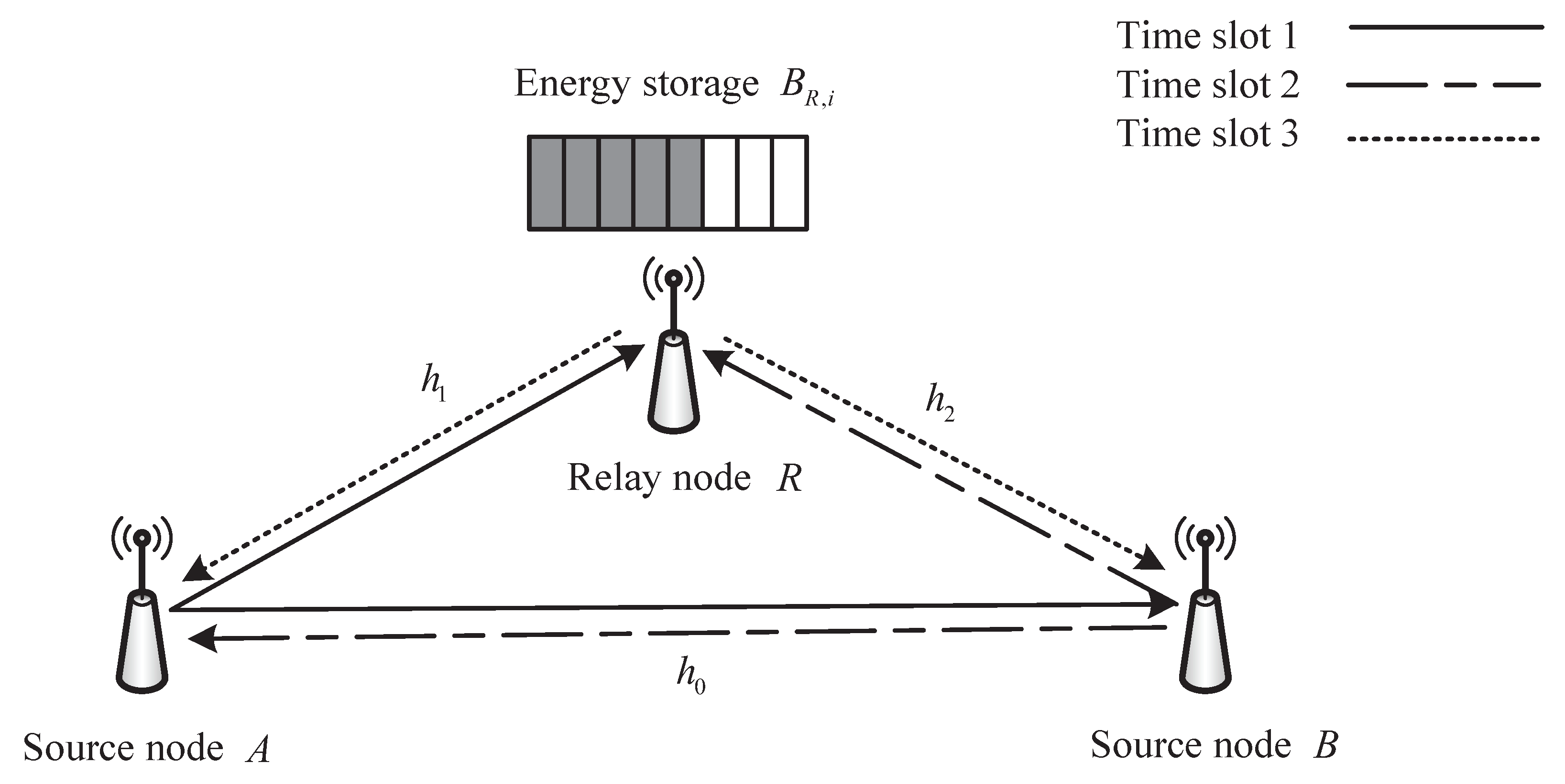
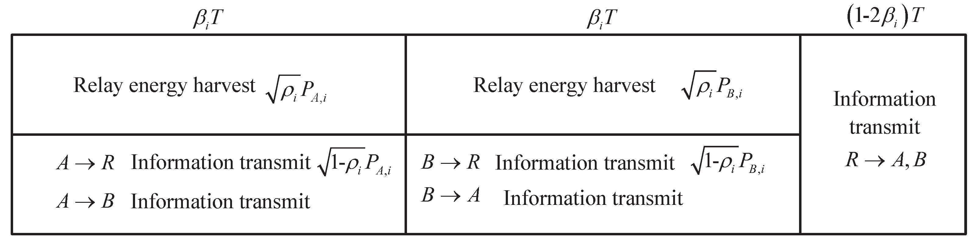
  • First, we construct a two-way single-relay communication system (SR-TWRS), in which the relay assists the source node in multiple two-way communications while collecting energy in conjunction with a TS broadcast transmission scheme. The relay uses the collected energy to assist in forwarding and accumulates and stores some of the energy for subsequent communications.
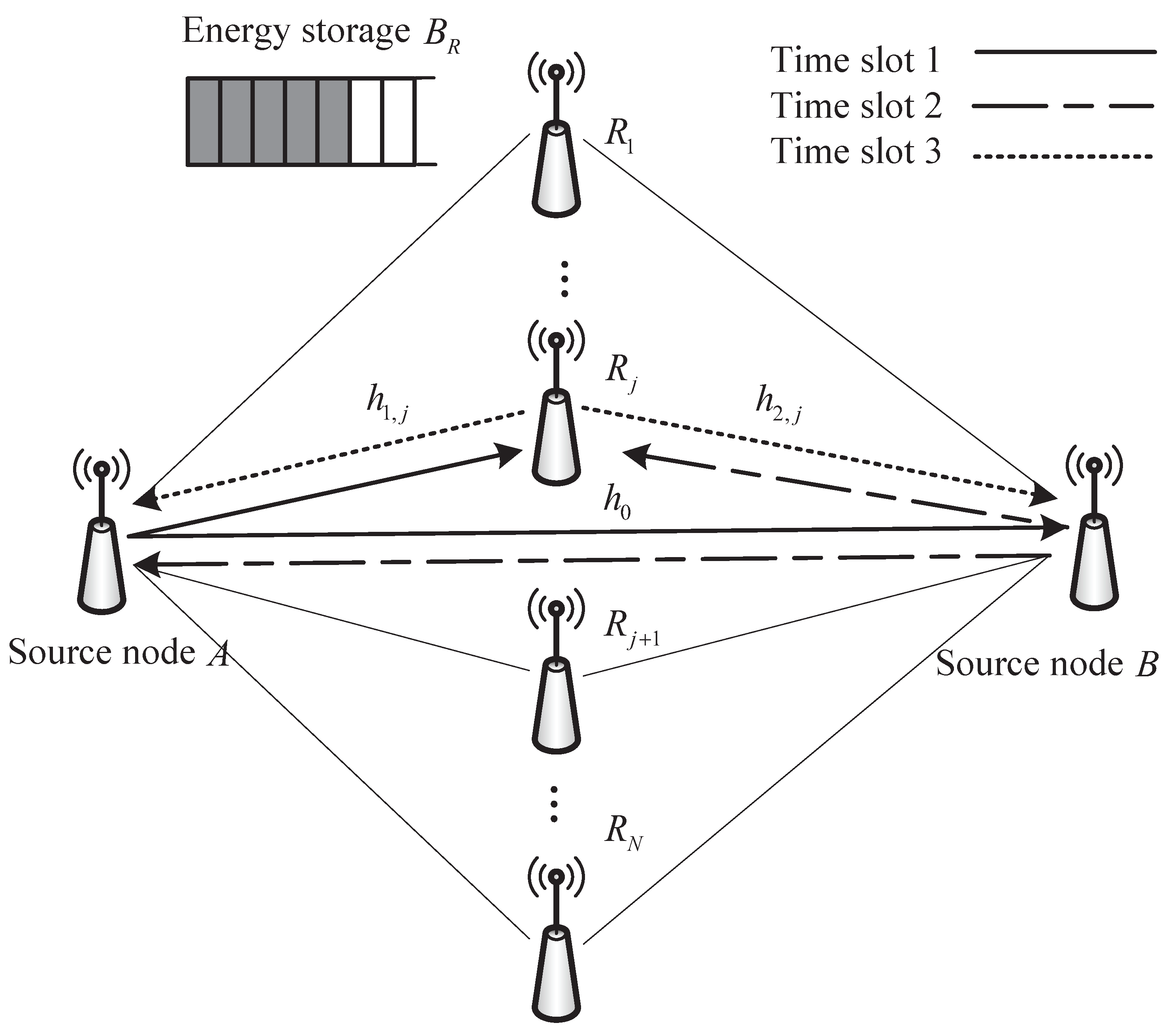
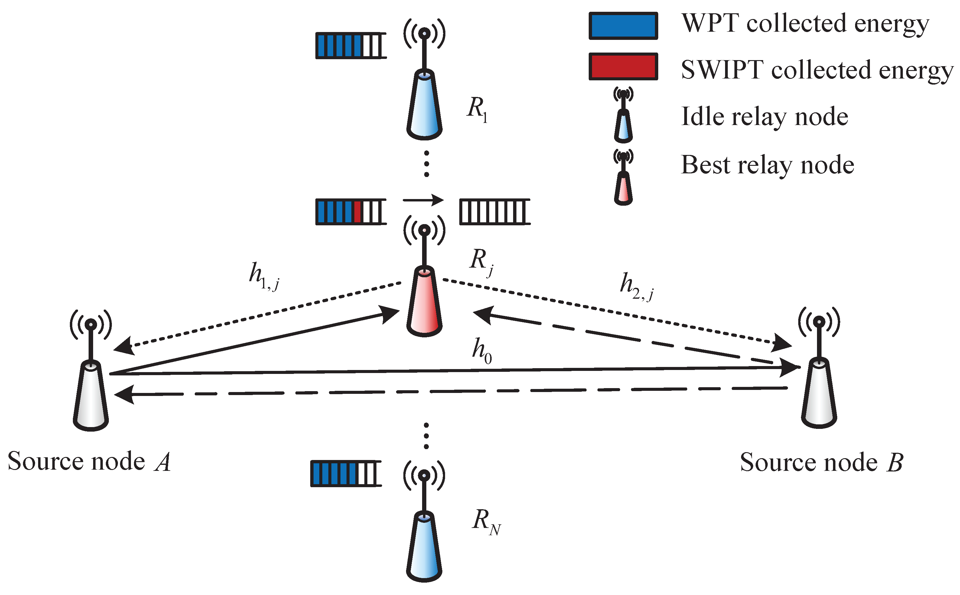
  • Second, the model is further extended to a two-way multi-relay communication system (MR-TWRS) by defining the system’s equivalent profitability. Only one optimal relay is selected to participate in collaborative communication at a time, and the relay selection is based on maximizing the system’s equivalent profit.
  • Finally, the optimal optimization problem for the instantaneous transmission rate in a two-way single-relay communication system is solved by the Lagrange dual method. Furthermore, based on this, the outage probability of a single node in the system is analysed theoretically, and the expression of outage probability is derived. The proposed joint optimization algorithm is demonstrated to have a significant improvement in the instantaneous transmission rate compared with the traditional comparison algorithm by simulation. In the two-way multi-relay communication system, our proposed accumulative energy based on SWIPT enhances the system equivalence profit significantly compared to the comparison algorithm

2. SWIPT in Two-Way Single-Relay Communication

2.1. System Model

As shown in Figure 1, the three-node two-way relay system, also known as the two-way single-relay communication system (SR-TWRS), includes two source nodes and one relay node. The three-time slot transmission scheme in three-node TWRS is also known as the time division broadcast (TDBC) scheme. Each node in the system is in half-duplex operation mode. The direct transmission link exists between source nodes but they cannot communicate independently due to the poor channel condition and the two source nodes have a fixed energy supply. The relay node, on the other hand, can only collect energy from the signal sent by the source node by means of SWIPT, which is used to supplement its own energy consumption used to assist the source node in forwarding the signal. For finding notations of this paper more conveniently, the key notations are listed in Table 2.
It is assumed that all channels in the system are independently and identically distributed with quasi-static Rayleigh flat fading, and all channels are mutually invertible. The channel coefficients are random variables obeying the complex Gaussian distribution, i.e., h C N 0 , d N θ / 2 , N 0 , 1 , 2 , where θ denotes the channel fading factor, and d N is the distance between nodes. In the i-th communication, the two-way relay communication consists of three time slots as follows.
As shown in Figure 2, T is the total duration of a two-way relay communication and is divided into three timeslots by the time slot allocation factor β i . Both time slot 1 and time slot 2 are β i T . Source node A broadcasts information in time slot 1 to relay node R and source node B. In time slot 2, source node B sends its message to relay node R and source node A. In timeslot 3 the relay R transfers the processed signal to the two source nodes in 1 2 β i T . It is assumed that the system operates in a symmetric mode, i.e., the amount of data in one two-way communication interaction is equal. In the i-th two-way relay communication, the source node A in time slot 1 sends RF signal x 1 , i and x 1 , i is a power normalized signal that satisfies E | x i | 2 = 1 . The relay node is mainly composed of an energy collection unit and a signal processing core unit. The received signal power is divided into two parts by a power splitting factor ρ i through the PS receiver, which is used to collect energy and decode information, respectively. Then the signals received by the relay R and the source node B in time slot 1 can be expressed, respectively, as follows,
y R , i 1 = 1 ρ i P A , i | h 1 , i | x 1 , i + 1 ρ i n 1 + n R
y B , i 1 = P A , i | h 0 , i | x 1 , i + n 0
The source node B in time slot 2 sends RF signals to the relay node R and the source node A in the same way, and then the received signal can be expressed as
y R , i 2 = 1 ρ i P B , i | h 2 , i | x 2 , i + 1 ρ i n 2 + n R
y A , i 2 = P B , i | h 0 , i | x 2 , i + n 0
where P N , i , N 0 , 1 , 2 are the transmit power of the two source nodes, respectively. n N , i is the additive Gaussian white noise satisfying a mean of 0 and a variance of σ N , i 2 . n R is the noise at the relay node due to power splitting with a power of σ R 2 .
Assuming the same power splitting factor at the relay nodes in the first two timeslots, the instantaneous information transmission rate of the relay nodes in the two time slots for the i-th two-way energy-carrying relay communication can be presented as follows, respectively.
R r , i 1 = β i T l n 1 + 1 ρ i P A , i | h 1 , i | 2 1 ρ i σ 1 2 + σ R 2
R r , i 2 = β i T l n 1 + 1 ρ i P B , i | h 2 , i | 2 1 ρ i σ 2 2 + σ R 2
Then the energy collected at the relay energy receiver can be given as
E R , i = η β i T ρ i P A , i | h 1 , i | 2 + P B , i | h 2 , i | 2
where η is the energy conversion efficiency of relay R. Its value depends on the receiver rectifier antenna and impedance matching circuit.
Relay node R decodes the information sent by the source node independently in the first two time slots in turn. Due to the service symmetry, the relay can choose to merge the two source messages by means of XOR. To ensure that the combined data has unit power, the combined data is denoted as x R , i = x 1 , i + x 2 , i / 2 . In time slot 3 the relay node sends the merged data to two source nodes through broadcasting. At this time, the two source nodes receive signals that can be expressed as follows, respectively.
y A , i 3 = P r , i | h 2 , i | x R , i + n 2 = P r , i | h 1 , i | 2 x 2 , i + P r , i | h 1 , i | 2 x 1 , i + n 1
y B , i 3 = P r , i | h 1 , i | x R , i + n 1 = P r , i | h 2 , i | 2 x 1 , i + P r , i | h 2 , i | 2 x 2 , i + n 2
Taking link A R B as an example, source node B combines the signal received in time slot 1 through the direct transmission link and the signal forwarded in time slot 3 through relay by the MRC technique to obtain the instantaneous information transmission rate,
R b , i 3 = 1 2 β T l n 1 + P A , i | h 0 , i | 2 σ 0 , i 2 + P r , i | h 2 , i | 2 2 σ 2 2
Similarly, the instantaneous information transmission rate at the source node A can be obtained by
R a , i 3 = 1 2 β T l n 1 + P B , i | h 0 , i | 2 σ 0 , i 2 + P r , i | h 1 , i | 2 2 σ 1 2
where P r , i is the relay forwarding power. In summary, the instantaneous transmission rate of the link A R B after the completion of a two-way energy-carrying relay communication can be expressed as
R a b , i = m i n R r , i 1 , R b , i 3
Set B R , i as the accumulated stored energy of the relay node after the end of the i-th two-way energy-carrying relay communication, and P c as the inherent consumption of the relay circuit for maintaining the circuit operation. The energy storage threshold of the relay node is B m a x . Considering the energy collected by the relay node each time, the energy consumption when sending messages and the inherent consumption, the stored energy at relay R should satisfy,
B R , i = m i n B R , i 1 + E R , i P r , i 1 2 β i T P c T , B m a x
where P r , i 1 2 β i T indicates the energy consumption used to send signals in one time period T.
Then, the energy available for relay-assisted forwarding consists of E r , i collected by SWIPT and the accumulated stored energy B R , i 1 . We call this SWIPT, which collects energy in a two-way single-relay communication network and stores it cumulatively, the relay energy accumulation SWIPT under SR-TWRS in this paper.

2.2. Problem Formulation

Combined with Equation (13), substitute B R , i 1 to obtain an equation that only relates to the variable, then the energy storage constraint is further obtained as
C 1 : B R , i = m i n k = 1 i E R , k k = 1 i P r , k 1 2 β k T i P c T , B m a x
Since the transmitting power of the relay node cannot be greater than the energy possessed by the node, the relay forwarding power should satisfy the constraint that,
C 2 : 1 2 β i P r , i T B R , i 1 + E R , i P c T
Combined with the non-negativity constraint of the transmitted power, the collected energy needs to meet at least the information transmission and the inherent consumption requirements. The minimum collection energy of the relay node should satisfy the following constraint.
C 3 : E r , i P r , i 1 2 β i T P c T
The instantaneous transmission rate optimization problem of link A R B in the i-th two-way energy-carrying relay communication can be formulated as
O P : max ρ i , P r , i , β i R a b , i s . t . C 1 , C 2 , C 3 C 4 : 0 ρ i 1 C 5 : 0 β i < 0.5
where C 4 , and C 5 are realistic constraints on the power splitting factor and the time slot allocation factor.

2.3. Joint Optimization Algorithm

The objective function in the optimization problem is a non-convex function with respect to ρ i . It needs to be solved by converting it into a convex problem. By solving the above problem equivalently by the Lagrange dual method [25], the Lagrange function of the optimization problem is expressed as
L ρ i , P r , i , β i = α 1 R r , i 1 R a b , i + α 2 R b , i 3 R a b , i + α 3 B m a x k = 1 i E R , k + k = 1 i P r , k 1 2 β k T + i P c T + α 4 E r , i P r , i 1 2 β i T P c T
where α = α 1 , α 2 , α 3 , α 4 are dual variables. The Lagrange dual function of the optimization problem can be written as
g α = m a x L ρ i , P r , i , β i
Further, the dual optimization problem can be expressed as
min α g α s . t . α 0
Since the dual function is derivable, the optimal solution for the dual variables is solved by the sub-gradient method. The central idea of this method is to update the dual variables by α t + 1 = α t + τ Δ α + in the direction of the vector satisfying the sub-gradient condition at a fixed step τ until the dual variables converge, where t is the number of iterations. According to the optimization problem, the sub-gradient of the above dual optimization problem can be derived as
Δ α 1 = R r , i 1 R a b , i
Δ α 2 = R b , i 3 R a b , i
Δ α 3 = B m a x k = 1 i E R , k + k = 1 i P r , k 1 2 β k T + i P c T
Δ α 4 = E r , i P r , i 1 2 β i T P c T
After obtaining the specific dual variables, the optimization factors can be solved separately by the following two steps.

2.3.1. Power Optimization

Let φ A , i = P A , i | h 1 , i | 2 , φ B , i = P B , i | h 2 , i | 2 . Given a fixed time slot allocation factor at the beginning of the iteration, the partial derivatives of the power splitting factor and relay forwarding power in the Lagrange function are obtained separately.
L ρ i , P r , i , β i ρ i = α 1 β i T φ A , i σ R 2 1 ρ i φ A , i + σ 1 2 + σ R 2 · 1 1 ρ i σ 1 2 + σ R 2 α 3 k = 1 i β k T η φ A , k + φ B , k + α 4 β i η φ A , i + φ B , i
L ρ i , P r , i , β i P r , i = α 2 1 2 β i T w 2 , i 1 + P A , i w 0 , i + P r . i w 2 , i + α 3 k = 1 i 1 2 β k T α 4 1 2 β i T
where w N , i = | h N , i | 2 σ N 2 . The optimal value of the power splitting allocation factor is obtained according to the KKT condition.
ρ i * = 1 σ R 2 φ A , i + 2 σ 1 2 + σ R 4 φ A , i + 2 σ 1 2 2 4 σ 1 2 φ A , i + σ 1 2 Y i 2 σ 1 2 φ A , i + σ 1 2 +
P r , i * = α 2 1 2 β i T α 4 1 2 β i T α 3 k = 1 i 1 2 β k T σ 2 2 | h 2 | 2 1 + P A , i | h 0 | 2 σ 0 2 +
where Y i = σ R 4 α 1 T φ A , i σ R 2 α 4 η φ A , i + φ B , i α 3 k = 1 i T η φ A , k + φ B , k , · + = m a x · , 0 . Based on the original constraint of the time slot allocation factor and the constraint C 3 , the new constraint range is obtained as
β i P c + P r , i ρ i η φ A , i + φ B , i + 2 P r , i , 0.5

2.3.2. Time Slot Optimization

To date, the instantaneous transmission rate of the link is only related to β i . By an exhaustive method, the time slot allocation factor which makes the largest objective function is the optimal value β i * by traversing the range of values of β i .
β i * = arg max β i R a b , i
where β i * is obtained as the initial value of the time slot allocation factor in the next iteration of power optimization. Repeat the above steps iteratively until the dual variables converge. Algorithm 1 summarizes the proposed algorithm for the joint optimization problem in the SR-TWRS scenario.
Algorithm 1 Proposed algorithm for the joint optimization problem in the SR-TWRS scenario.
Initialize: Given the dual variables α t , the iteration step size τ , convergence parameter ϵ and time slot allocation factor β i 1 . Let t = 1 .
 1:
repeat
 2:
   Calculate ρ i t and P r , i t according to (27) and (28).
 3:
   Update the value interval of β i t + 1 and take the value according to β i t + 1 = arg max β i R a b , i .
 4:
   Update dual variables α t + 1 and set t = t + 1 .
 5:
until | α t + 1 α t | ϵ

2.4. Outage Probability Analysis

In this section, the analysis is performed for the single node outage probability in the system. To facilitate subsequent calculations, let x = | h 1 , i | 2 , y = | h 2 , i | 2 and z = | h 0 | 2 . Since | h N | 2 obeys an exponential distribution with parameter d N θ , its probability density function can be expressed as f x = λ 1 e λ 1 x , f y = λ 2 e λ 2 y and f z = λ 0 e λ 0 z , where λ N is the channel gain density function variable and λ N = d N θ . The relay node R participates in collaborative communication based on the DF protocol. The outage probability of link transmission is the outage probability at any hop. The SINR at the relay node R and the source node B can be, respectively, expressed as
γ R 1 = 1 ρ i P A , i | h 1 , i | 2 1 ρ i σ 1 2 + σ R 2
γ B , i = P r , i | h 2 , i | 2 2 σ 2 2 + P A , i | h 0 | 2 σ 0 2
Then the outage probability at the source node B can be expressed as
P B o u t , i = 1 P γ R 1 γ t h P γ B , i γ t h = 1 P r | h 1 , i | 2 γ t h 1 ρ i σ 1 2 + σ R 2 1 ρ i P A , i P r | h 2 , i | 2 γ t h P A , i | h 0 | 2 σ 0 2 2 σ 2 2 P r , i = 1 e λ 1 γ t h 1 ρ i σ 1 2 + σ R 2 1 ρ i P A , i 0 e λ 2 γ t h P A , i z σ 0 2 2 σ 2 2 P r , i λ 0 e λ 0 z d z = 1 λ 0 e ψ B , i λ 0 ϕ B , i
where ψ B , i = λ 1 γ t h 1 ρ i σ 1 2 + σ R 2 1 ρ i P A , i + 2 λ 2 γ t h σ 2 2 P r , i , ϕ B , i = 2 λ 2 P A , i σ 2 2 σ 0 2 P r , i holds in condition P r , i > 2 λ 2 P B , i σ 1 2 σ 0 2 . Similarly, the expression for the outage probability at the source node A during the i-th two-way energy-carrying relay communication can be obtained as P A o u t , i = 1 λ 0 e ψ A , i λ 0 ϕ A , i , where ψ A , i = λ 2 γ t h 1 ρ i σ 2 2 + σ R 2 1 ρ i P B , i + 2 λ 1 γ t h σ 1 2 P r , i , ϕ A , i = 2 λ 1 P B , i σ 1 2 σ 0 2 P r , i .

3. SWIPT in Two-Way Multi-Relay Communication

In collaborative relay networks, as the relay is often configured with only a single antenna, a virtual antenna array composed of relay nodes can be used to enhance spatial diversity and improve system throughput and user quality of service.

3.1. System Model

As shown in Figure 3, the two-way multi-relay relay system (MR-TWRS) includes two sources and multiple relay nodes. Each node in the system is in half-duplex operation mode, where both source nodes have a fixed energy supply. The relay nodes can collect the energy in the RF signal sent by the source node through WPT and SWIPT to assist in information transmission. In a two-way energy-carrying communication, one optimal relay node is selected at a time to assist the two-way communication. Meanwhile, direct transmission links exist between the source nodes but they cannot communicate independently because of the poor channel conditions.
As in Figure 2, the two-way communication duration T is split into β i T , β i T and 1 2 β i T . It is assumed that the best relay R j is selected to assist the source node in the i-th two-way energy-carrying relay communication, and the power splitting factor is ρ i . When R j is not selected, the RF signal energy sent by the source node can be collected by WPT, and this part of energy can be expressed as
E 1 , i = k = 1 i 1 β k T P A , k | h 1 , j | 2 + P B , k | h 2 , j | 2
where P A , k and P B , k are the transmit power of the two source nodes during the first i 1 two-way energy-carrying relay communication.
In this section, it is assumed that relay nodes do not have energy storage thresholds. In the i-th two-way energy-carrying relay communication, source node A in time slot 1 transmits signal x 1 , i to source node B and the relay node R j , and source node B in time slot 2 sends signal x 2 , i , and the process is the same. Then the energy collected by A in the first two time slots by means of SWIPT can be expressed as
E 2 , i = η β i T ρ i P A , i | h 1 , j | 2 + P B , i | h 2 , j | 2
where η is the relay energy conversion efficiency. Each relay node in the network collects energy in the same way as R j , as shown in Figure 4.
Depending on the relay selection benchmark, the system may select the best relay node differently each time. Excluding the inherent consumption of relay circuit operation, all the energy collected when a relay node is selected to participate in collaborative communication is used to forward messages in the broadcast phase. Then the relay forwarding power can be expressed as
P r , i = E 1 , i + E 2 , i i P c T 1 2 β T
This kind of SWIPT that combines WPT for energy accumulation in two-way multi-relay communication is defined as accumulative energy based on SWIPT under MR-TWRS. The selected relay node uses XOR to merge and process the information of the two source nodes to obtain the power normalized signal x R , i and then broadcast. Then the source node, after removing its own signal from the signal received in time slot 3, merges the two signals of time slot 1 and time slot 3 by the MRC technique. The end-to-end instantaneous transmission rate of the source node can be obtained by
R a b , i = 1 2 β i T l n 1 + P A , i | h 0 | 2 σ 0 2 + P r , i | h 2 , j | 2 2 σ 2 2
R b a , i = 1 2 β i T l n 1 + P B , i | h 0 | 2 σ 0 2 + P r , i | h 1 , j | 2 2 σ 1 2
Due to the energy limitation of relay nodes, the system energy consumption is considered to save energy and thus extend the network lifetime. The system energy consumption during the i-th two-way energy-carrying relay communication is defined as
U i = β i T P A , i + P B , i + E 2 , i
It is worth noting that the energy E 1 , i collected by the WPT method is used as an additional energy supplement for the relay nodes, which is not considered as the system energy consumption for this two-way energy-carrying relay communication. Two new variables, v 1 and v 2 , are further introduced, where v 1 is the equivalent profit per unit of throughput and v 2 is the equivalent cost per unit of system energy spent. The system equivalent profit is defined as the difference between the system information transmission profit and the system energy consumption cost v 1 R a b , i + R b a , i v 2 U i .

3.2. Problem Formulation

In our two-way multi-relay system, the optimization objective is to maximize the system equivalent profit with optimal relay collaboration. The optimization problem is divided into two sub-problems, defined as the inner and outer optimization problems, respectively. In the inner optimization problem, the initially selected relay node is presumed to be the best relay, and the maximum equivalent profit of the system is obtained by the joint time allocation and power splitting (JTAPS) optimization method on the basis of the selected relay. In the outer optimization problem, all relay nodes of the system are traversed by exhaustive enumeration, and the relay that makes the system equivalent profit the largest is the best relay node. Then the intra-optimization problem of system profitability in the ith two-way energy-carrying relay communication can be illustrated as
O P : max ρ i , β i v 1 R a b , i + R b a , i v 2 U i s . t . C 1 : E 2 , i P c T C 4 : 0 ρ i 1 C 5 : 0 β i < 0.5
where C 1 is the constraint on E 2 , i when the first relay node selected by the MR-TWRS system does not exist E 1 , i . C 2 and C 3 are realistic constraints made on the power splitting factor and the time slot allocation factor. Since the objective function in the optimization problem does not satisfy the convex function condition, the Lagrange dual method is used to equivalently solve the original optimization problem. Then its Lagrange function can be expressed as
L β i , ρ i = v 1 1 2 β i T l n l n 1 + P B , i w 0 , 1 + P r , i w 1 , i + l n 1 + P A , i w 0 , i + P r , i w 2 , i v 2 β i P A , i + P B , i + E 1 , i + λ E 2 , i P c T
where w N , i = | N n | 2 σ N 2 , N = 0 , 1 , 2 and λ is a non-negative dual variable. The dual function of the optimization problem can be expressed as
g λ = max ρ i , β i L β i , ρ i
The original optimization problem can be solved by the dual optimization problem
m i n g λ s . t . λ > 0
The optimal dual variable is obtained by the sub-gradient method, where the dual variable is updated iteratively by λ t + 1 = λ t + τ Δ λ . The algorithm flow is as follows.

3.2.1. Power Optimization

The time slot allocation factor β i and the power splitting factor ρ i are initialized. Then the partial derivative of the Lagrange function can be found,
L ρ i = v 1 η β i T φ A , i + φ B , i 2 w 2 1 + P A , i w 0 + 1 2 P r , i w 2 + w 1 1 + P B , i w 0 + 1 2 P r , i w 1 v 2 η β i T φ A , i + φ B , i + λ η β i T φ A , i + φ B , i
where φ A , i = P A , i | h 1 | 2 , φ B , i = P B , i | h 2 | 2 . The optimal value ρ i * can be obtained by bringing Equation (44) into Equation (36) and combining it with the KKT condition.

3.2.2. Time Slot Optimization

The time slot allocation factor β i is optimized after obtaining the optimal power splitting factor ρ i * . By taking partial derivatives of the Lagrange function, we obtain
L β i = 2 T v 1 l n 1 + P A , i w 0 + 1 2 P r , i w 2 + l n 1 + P B , i w 0 + 1 2 P r , i w 1 + η ρ i φ A , i + φ B , i + η k = 1 i 1 φ A , k + φ B , k 2 i P c 1 2 β i v 2 λ T 2 v 2 T P A , i + P B , i + η ρ i φ A , i + φ B , i + η T k = 1 i 1 φ A , i + φ B , i + λ T η ρ i φ A , i + φ B , i
The optimal value β i * is also obtained by the KKT condition, which is brought in as the initial value in the next iteration of power optimization.

3.2.3. Dual Variable Update

The dual variable is updated according to Δ = E 2 , i P c T . This is repeated until the dual variable converges. The specific flow of the alternating iteration step of the optimization factor in the internal optimization joint time allocation and power splitting algorithm is shown in Algorithm 2.
Algorithm 2 Proposed algorithm for the joint optimization problem in the MR-TWRS scenario.
Initialize: Given the dual variable λ t , the iteration step size τ , convergence parameter ϵ and time slot allocation factor β i 1 . Let t = 1 .
 1:
repeat
 2:
   Substituting β i t to obtain the power splitting factor ρ i t according to (44) and the KKT condition.
 3:
   Substitute ρ i t to obtain β i t + 1 as the initial value of the next iteration according to (45) and the KKT condition.
 4:
   Update dual variable λ t + 1 and set t = t + 1 .
 5:
until | λ t + 1 λ t | ϵ
The maximum equivalent profit of the system under the initialized relay node is obtained after the inner optimization problem is solved. In this section, the relay selection strategy is to maximize the system profitability, when the objective function in the outer optimization problem is only related to the relay nodes. Then the optimal relay node can be obtained by
R j * = arg max R j v 1 R a b , i + R b a , i v 2 U i

4. Simulation Results

In this paper, the total duration of one two-way communication is T = 1 s , during which we simulated 20 times of two-way energy-carrying relay communication. Noise power due to power splitting at the relay node is σ R 2 = 4 × 10 4 W . In the system equivalent profit, the equivalent benefit per unit of throughput is v 1 = 1.5 and the equivalent cost per unit of system energy spent is v 2 = 1.0 . The remaining parameters are shown in Table 3.

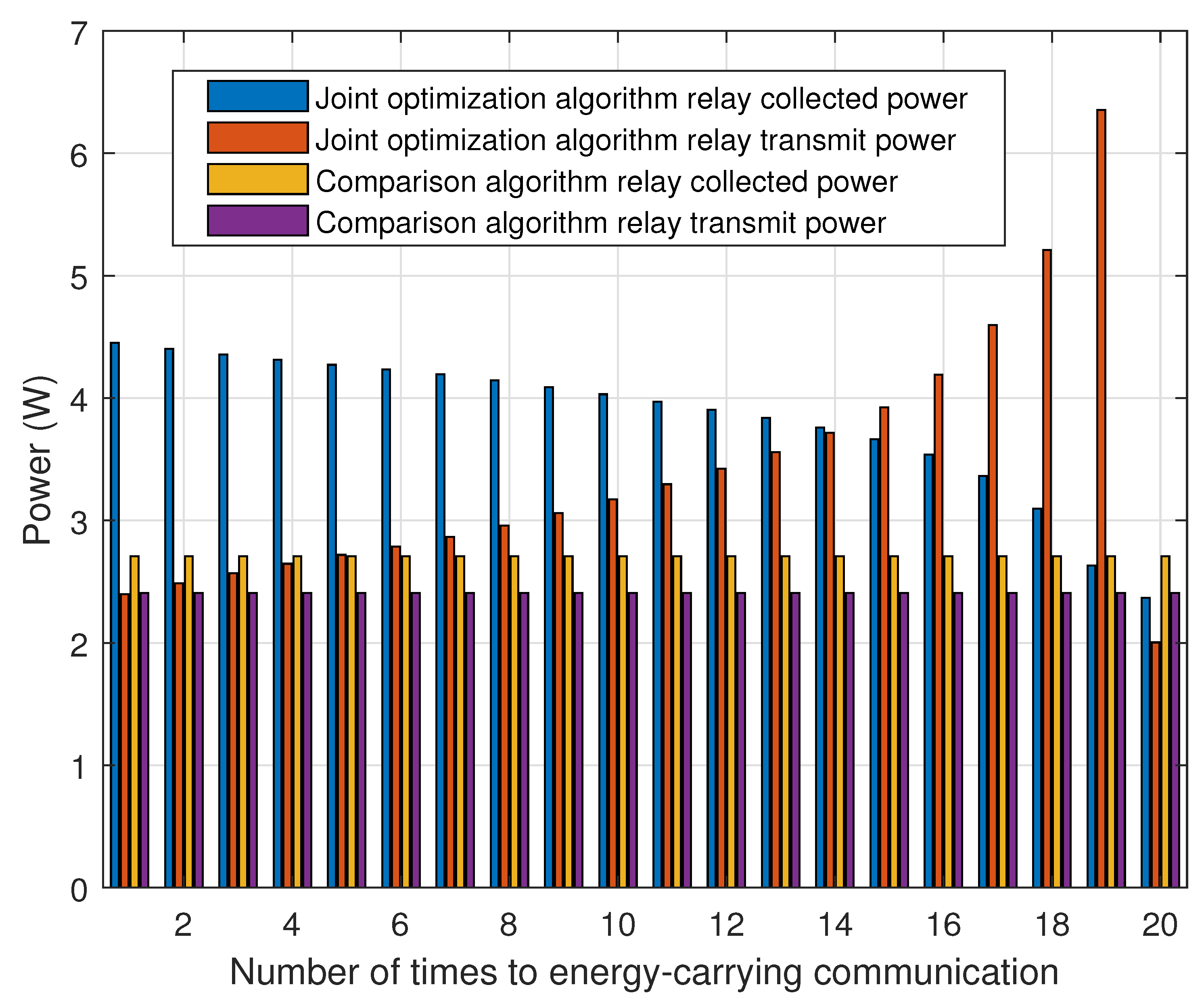
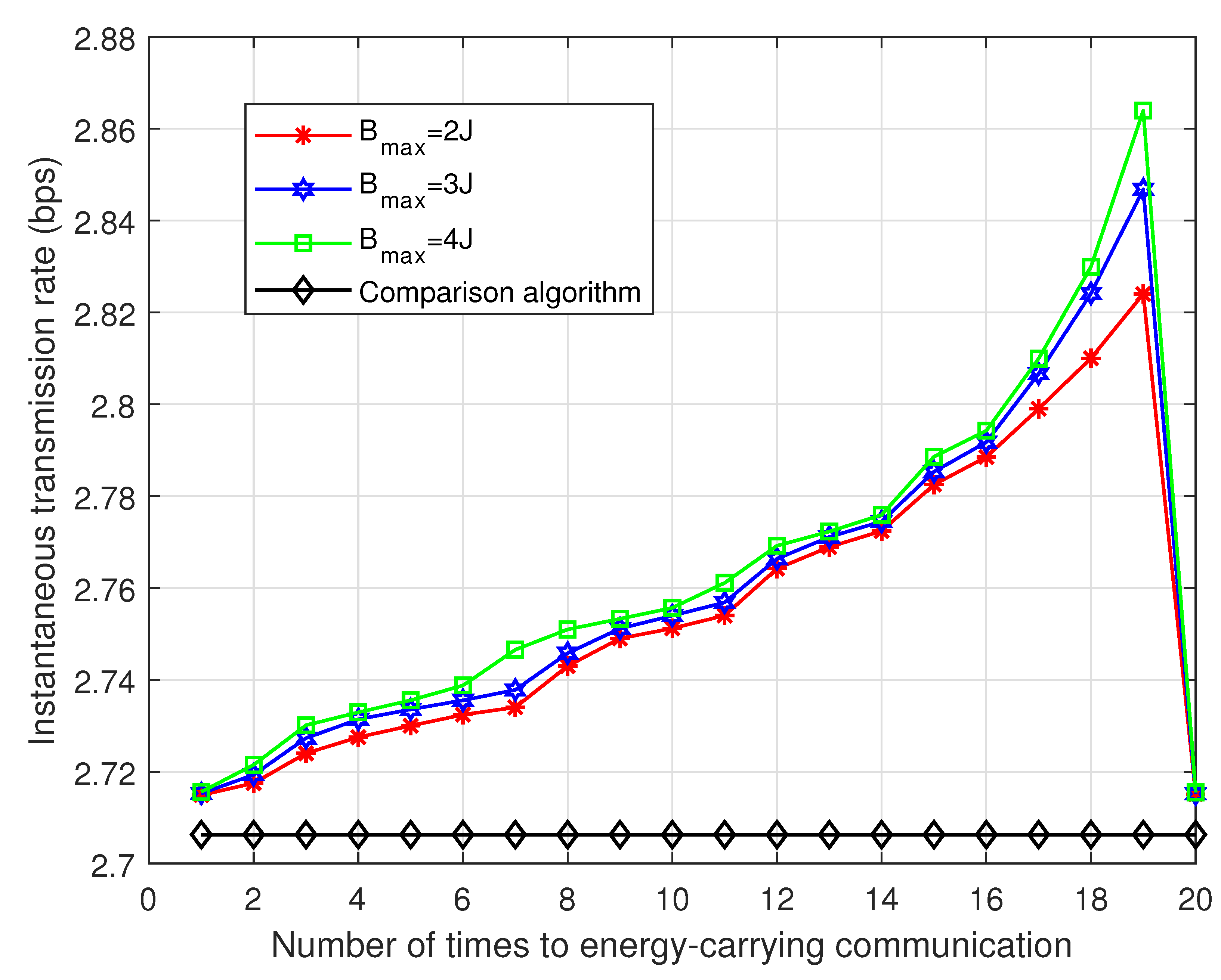
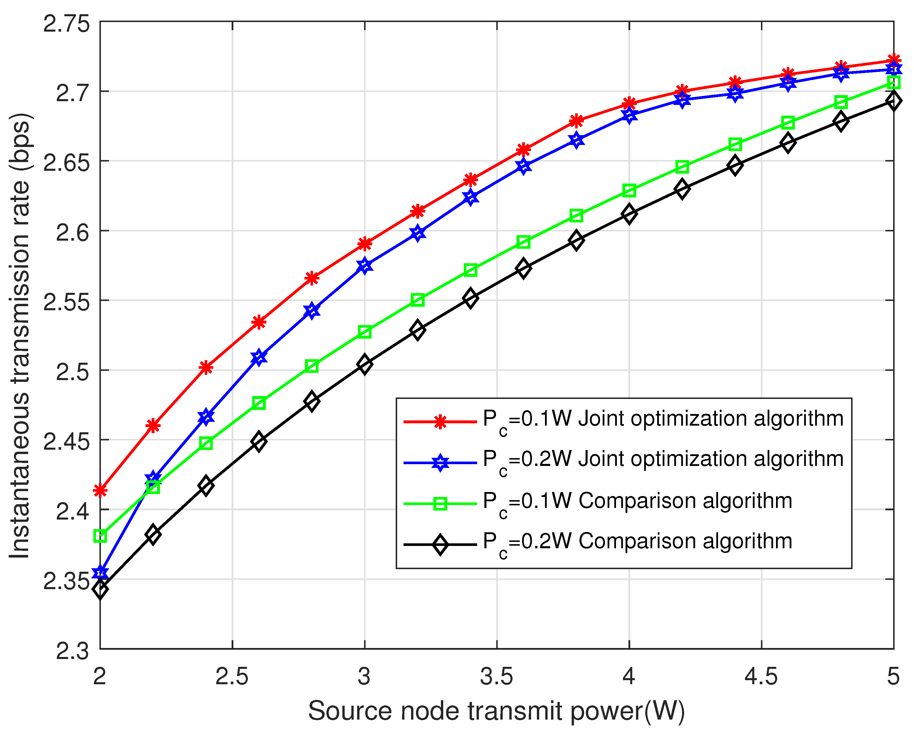
4.1. SR-TWRS Scenario Analysis

Figure 5 shows the comparison of the energy collected by the relay and the transmission power under the joint optimization algorithm and the comparison algorithm, where the comparison algorithm is also a two-way energy-carrying relay communication under the TDBC transmission scheme. The relay node assists the communication between the source nodes through the SWIPT method based on DF collaborative communication. The difference is that the energy collected by the relay is all used for the next time slot forwarding, i.e., non-accumulative energy based on SWIPT, which maximizes the instantaneous transmission rate of the link by optimizing the power splitting factor only.
Simulation results are given for the joint optimization algorithm and the comparison algorithm in cases B m a x = 3 J and P i = 5 W . For the comparison algorithm, the relay transmitted power for each two-way communication is equal to the collected power minus the inherent power consumed by the relay circuit. For the joint optimization algorithm, the relay forwarding energy is part of the accumulated energy during the initial energy-carrying communication, and the remaining energy is stored for subsequent communication. As the relay transmitted power also participates in the optimization process of the objective function, a further degree of freedom is added to the SR-TWRS system. As the number of communications increases, the collected energy decreases but the relay transmitted power can continue to increase due to the support of stored energy. In Figure 5, the relay collected energy is less than the relay transmitted power in the 14th two-way communication, i.e., the relay node starts to use the stored energy to assist in forwarding. It can also be seen in conjunction with Figure 6 that the relay storage energy starts to decrease at the 14th two-way carry communication.
Figure 6 shows the instantaneous transmission rate of the link obtained with different energy storage thresholds set at transmit power of P i = 5 W . As can be seen from Figure 6, the instantaneous transmission rate obtained by the joint optimization algorithm is significantly higher than that of the comparison algorithm, even in the first two-way energy-carrying communication, i.e., the worst instantaneous transmission rate in the joint optimization algorithm. This is because the multi-factor optimization in the joint optimization algorithm adds an additional degree of freedom compared to the comparison algorithm, allowing a more rational allocation of resources to achieve higher instantaneous transmission rates. In addition, as the energy storage threshold increases, the relay node can store more energy, which enhances the relay forwarding power, thus making the broadcast link instantaneous transmission rate increase.
Figure 7 shows the relay node energy collection curves for different energy storage thresholds in case P i = 5 W . The energy storage accumulation is the same until the relay collected energy reaches the threshold. After the collected energy is not enough for this communication, the relay forwarding message starts to consume the stored energy. When all the stored energy is consumed, i.e., B = 0 , the instantaneous transmission rate reaches the maximum value. Combining Figure 6 and Figure 7, the above process is repeated at the next energy-carrying communication to obtain a periodic variation of the instantaneous initial rate.
Figure 8 shows the comparison of the instantaneous transmission rate between the joint optimization algorithm and the comparison algorithm in the 1st two-way energy-carrying relay communication (i.e., the worst instantaneous transmission rate) with different inherent consumption of the relay circuit in the case of B m a x = 3 J with different transmitted powers. As can be seen from the figure, the instantaneous transmission rate in both the joint optimization algorithm and the comparison algorithm increases as the transmitted power increases for a certain intrinsic consumption of the relay circuit. At a certain transmit power, the inherent consumption of the relay circuit increases under the same algorithm making less energy available for relay forwarding, which further reduces the instantaneous transmission rate.
Figure 9 shows the curves of the single node outage probability for different SNR thresholds at different node distances. From the figure, it can be observed that as the SINR threshold increases, the node outage probability increases. With the increase in distance between nodes, the signal attenuation increases and the signal outage probability increases as well.

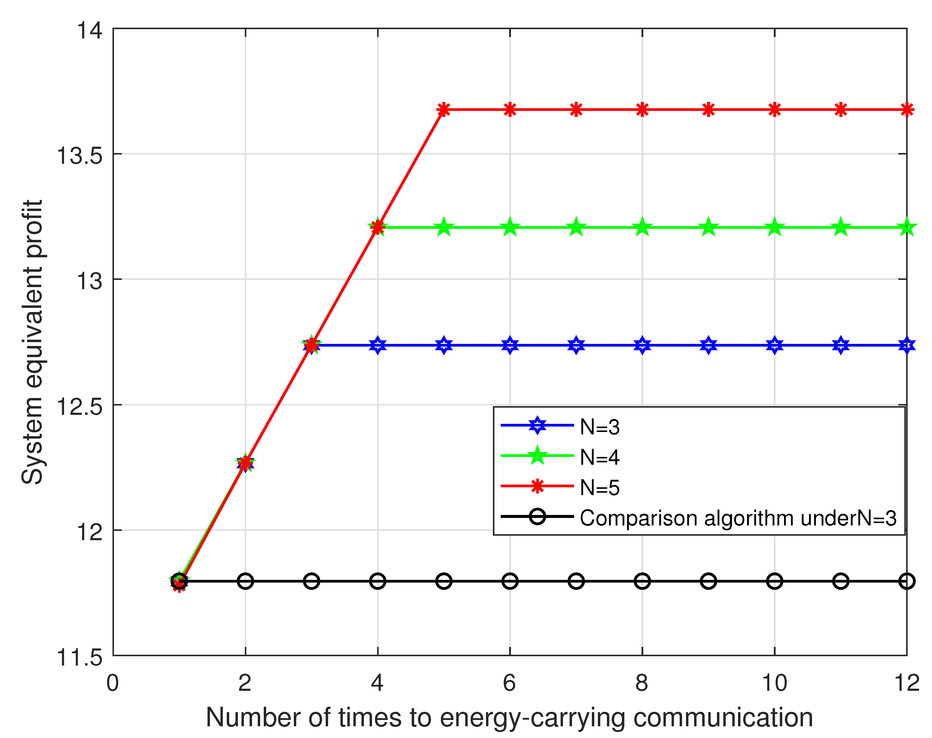
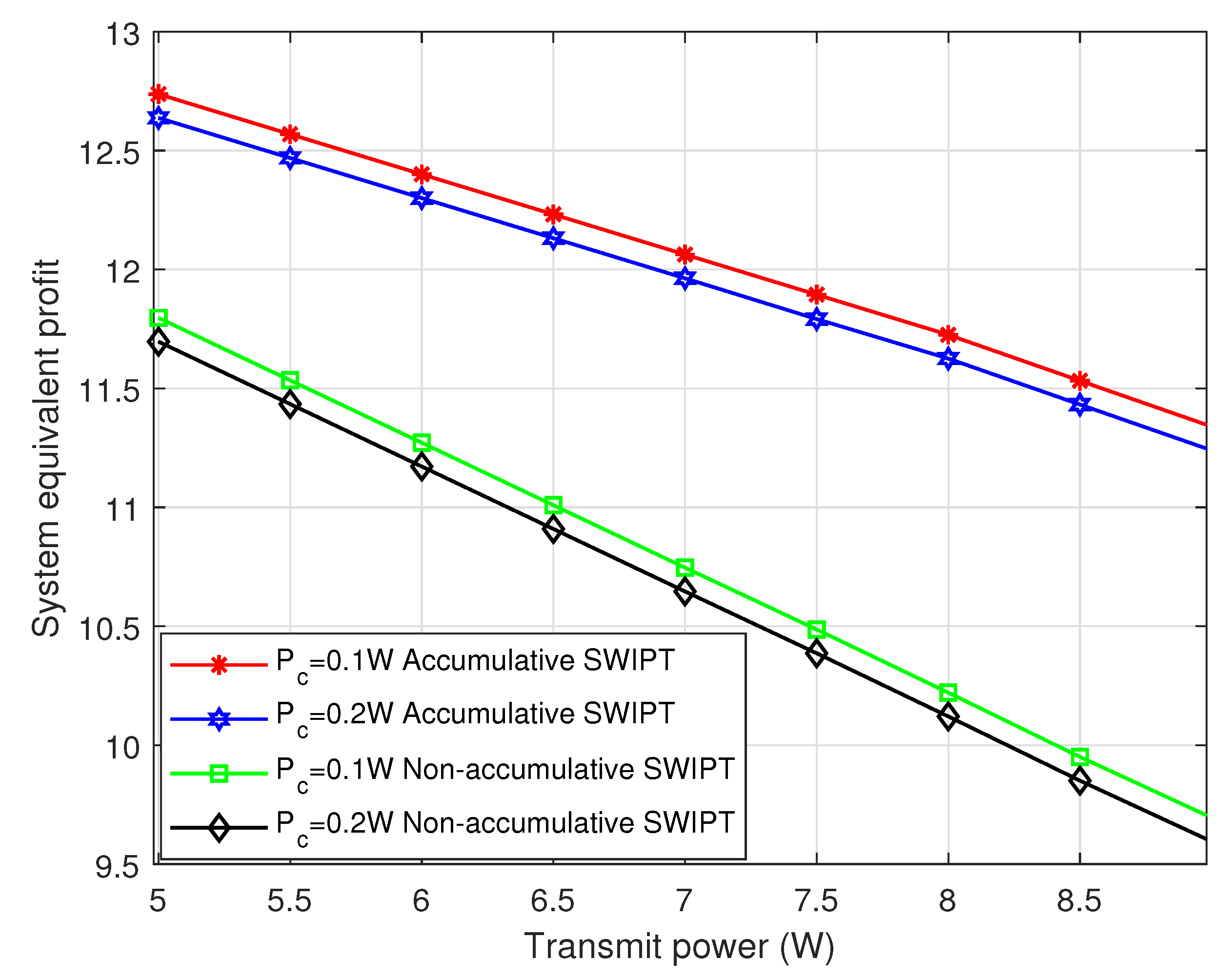
4.2. MR-TWRS Scenario Analysis

The comparison algorithm considered in this section is non-cumulative energy based on SWIPT, that is, the relay node does not collect energy by WPT. When a relay is unselected, it is idle. The energy collected by SWIPT only after being selected, and all the collected energy is used to assist in information forwarding. Each relay node collects energy independently.
Figure 10 shows the comparison of the system equivalent profit obtained by cumulative energy based on SWIPT with different numbers of relays in MR-TWRS and the comparison with the system equivalent profit obtained by non-cumulative based on SWIPT at the number of relays N = 3 . The system’s equivalent profit is the same in both ways because the relay nodes do not have any form of energy storage during the first energy-carrying communication. For the second and third energy-carrying communication, the relay node that maximizes the system equivalent profit is selected according to the optimization objective algorithm. From the simulation results, it can be seen that the relay node with more energy collected by WPT and stored energy will be selected first. This is because the end-to-end instantaneous transmission rate increases due to the increased energy available to the relay node for forwarding, which results in an increase in the system’s equivalent profit as well. Once selected for collaborative communication, all forms of energy previously stored by the relay node will assist in forwarding. At the fourth communication, the relay node in N = 3 scenario can collect energy by WPT at most 2 times. At this time, all relay nodes in the system have been selected, and the relay node with 2 times of WPT energy is selected for each subsequent energy-carrying communication, so the system is equivalent to a stable profit. In the N = 4 scenario, compared to N = 3 , the relay node can collect the energy by WPT up to 3 times, so the equivalent profit of the system is larger. As the number of energy-carrying communications increases, the system equivalent profit is greater for the N = 5 scenario, and the system equivalent profit obtained subsequently is stable.
Figure 11 shows the variation of energy collected by WPT for different relay nodes as the number of energy-carrying communications increases in the N = 3 scenario, and the relay nodes selected for each energy-carrying communication are marked in the figure. In the first energy-carrying communication, the unselected relay nodes collect and store energy by WPT, while the selected relay node collects energy by SWIPT, and all forms of energy collected are used for collaborative communication. In the second energy-carrying communication, the same as the simulation results in Figure 10, the relay node with more stored energy will be selected to participate in the collaborative communication according to the optimized target algorithm, and the same for the subsequent energy-carrying communication. The selected relay node can also be visualized from the figure, because relay nodes need to use all the stored energy for forwarding, so the relay node with E 1 , i = 0 at the end of each energy-carrying communication is the best relay selected to assist the two-way communication between source nodes in the system.
The minimum transmitted power P m i n = 5 W of the source node is set to ensure that the selected relay node can decode the received information correctly. Figure 12 shows the variation curves of the system equivalent profit under accumulative energy based on SWIPT for different transmitting powers in N = 3 scenario, and the comparison with the system equivalent profit under non-accumulative energy based on SWIPT. The system equivalent profit obtained under the accumulative energy based on SWIPT is significantly higher than the system equivalent profit under the comparison scheme. At the same time, the system equivalent profit obtained decreases continuously as the transmitting power increases. This is because an increase in transmitted power further leads to an increase in system energy consumption and the cost required for two-way communication. The impact of increasing transmitted power on the system equivalent profit is relatively small and leads to an overall decrease in the system equivalent profit. Furthermore, from Figure 12, it can be seen that in the same SWIPT approach, as the inherent consumption of the relay circuit increases, the increase in system energy cost also leads to a decrease in system equivalent profit.

5. Conclusions

At present, in the two-way relay communication system combined with SWIPT, the relay often uses all the energy collected to participate in collaborative communication, ignoring the feature that the relay node can store and accumulate energy, which can be improved to further extend the freedom of the system. In this paper, we divide the network into two models, SR-TWRS and MR-TWRS, in the context of two-way energy-carrying relay communication networks, and consider the energy storage of relay nodes under these two system models. TDBC transmission scheme is also used for the direct transmission links present in the system, and the system diversity gain can be improved by merging techniques at the receiving end. By jointly optimizing the relay selection, time slot allocation factor, power splitting factor and relay forwarding power for the instantaneous transmission rate and the system equivalent profit, our proposed algorithm improves the performance of the system compared with the comparison algorithm.

Author Contributions

Conceptualization, X.R. and G.W.; methodology, X.R.; software, X.R.; validation, X.R., X.W. and B.L.; formal analysis, X.R.; investigation, X.R., G.W. and X.W.; resources, X.W. and B.L.; data curation, X.R. and X.W.; writing—original draft preparation, X.R.; writing—review and editing, X.R. and X.W.; visualization, X.R.; supervision, X.W. and B.L.; project administration, G.W. and B.L.; funding acquisition, G.W. All authors have read and agreed to the published version of the manuscript.

Funding

This research was funded by the National Natural Science Foundation of China grant number 62171154, the Natural Science Foundation of Shandong Province grant number ZR2020MF007, the Natural Science Foundation of Shandong Province grant number ZR2020MF013 and the Research Fund Program of Guangdong Key Laboratory of Aerospace Communication and Networking Technology grant number 2018B030322004.

Institutional Review Board Statement

Not applicable.

Informed Consent Statement

Not applicable.

Data Availability Statement

Data are available upon request from the corresponding author.

Conflicts of Interest

The authors declare no conflict of interest.

References

  1. Ruan, T.; Chew, Z.J.; Zhu, M. Energy-aware approaches for energy harvesting powered wireless sensor nodes. IEEE Sens. J. 2017, 17, 2165–2173. [Google Scholar] [CrossRef]
  2. Zhang, Y.; Lu, T.; Zhao, Z.; He, F.; Chen, K.; Yuan, L. Selective wireless power transfer to multiple loads using receivers of different 480 resonant frequencies. IEEE Trans. Power Electron. 2015, 30, 6001–6005. [Google Scholar] [CrossRef]
  3. Khan, T.A.; Yazdan, A.; Heath, R.W. Optimization of power transfer efficiency and energy efficiency for wireless-powered systems with massive MIMO. IEEE Trans. Wirel. Commun. 2018, 17, 7159–7172. [Google Scholar] [CrossRef]
  4. Zhang, R.; Ho, C.K. MIMO broadcasting for simultaneous wireless information and power transfer. IEEE Trans. Wirel. Commun. 2013, 12, 1989–2001. [Google Scholar] [CrossRef]
  5. Alsharoa, A.; Ghazzai, H.; Kamal, A.E.; Kadri, A. Wireless RF-based energy harvesting for two-way relaying systems. In Proceedings of the 2016 IEEE Wireless Communications and Networking Conference, Doha, Qatar, 3–6 April 2016; IEEE: Piscataway, NJ, USA, 2016. [Google Scholar]
  6. Do, T.P.; Song, I.; Kim, Y.H. Simultaneous wireless transfer of power and information in a decode-and-forward two-way relaying network. IEEE Trans. Wirel. Commun. 2017, 16, 1579–1592. [Google Scholar] [CrossRef]
  7. Pelechrinis, K.; Yan, G.; Eidenbenz, S. Detection of Selfish Manipulation of Carrier Sensing in 802.11 Networks. IEEE Trans. Mob. Comput. 2012, 11, 1086–1101. [Google Scholar] [CrossRef]
  8. Liu, L.; Zhang, R.; Chua, K.C. Wireless information and power transfer: A dynamic power splitting approach. IEEE Trans. Commun. 2013, 61, 3990–4001. [Google Scholar] [CrossRef]
  9. Shi, Q.; Liu, L.; Xu, W.; Zhang, R. Joint transmit beamforming and receive power splitting for MISO SWIPT systems. IEEE Trans. Wirel. Commun. 2014, 13, 3269–3280. [Google Scholar] [CrossRef]
  10. Khandaker, M.R.A.; Masouros, C.; Wong, K.-K.; Timotheou, S. Secure SWIPT by exploiting constructive interference and artificial noise. IEEE Trans. Commun. 2018, 67, 1326–1340. [Google Scholar] [CrossRef]
  11. Zhang, J.; Tao, X.; Wu, H.; Zhang, X. Secure transmission in SWIPT-powered two-way untrusted relay networks. IEEE Access 2018, 6, 10508–10519. [Google Scholar] [CrossRef]
  12. Zhang, H.; Li, C.; Huang, Y.; Yang, L. Secure beamforming for SWIPT in multiuser MISO broadcast channel with confidential messages. IEEE Commun. Lett. 2015, 19, 1347–1350. [Google Scholar] [CrossRef]
  13. Li, Q.; Zhang, Q.; Qin, J. Secure relay beamforming for SWIPT in amplify-and-forward two-way relay networks. IEEE Trans. Veh. Technol. 2016, 65, 9006–9019. [Google Scholar] [CrossRef]
  14. Gao, R.; Xu, L.; Xu, D.; Bao, J. Trust-Degree-Based Secure Relay Selection in SWIPT-Enabled Relay Networks. Electronics 2023, 12, 429. [Google Scholar]
  15. Lee, K.; Lee, W. Deep Learning Framework for Two-Way MISO Wireless-Powered Interference Channels. IEEE Trans. Wirel. Commun. 2023; in press. [Google Scholar] [CrossRef]
  16. Nasir, A.A.; Zhou, X.; Durrani, S.; Kennedy, R.A. Relaying protocols for wireless energy harvesting and information processing. IEEE Trans. Wirel. Commun. 2013, 12, 3622–3636. [Google Scholar] [CrossRef]
  17. Nasir, A.A.; Zhou, X.; Durrani, S.; Kennedy, R.A. Throughput and ergodic capacity of wireless energy harvesting based DF relaying network. In Proceedings of the 2014 IEEE International Conference on Communications (ICC), Sydney, Australia, 10–14 June 2014; IEEE: Piscataway, NJ, USA, 2014. [Google Scholar]
  18. Zhong, K.; Fu, L. Throughput Maximization for the Full-Duplex Two-Way Relay System with Energy Harvesting. Electronics 2023, 12, 16. [Google Scholar] [CrossRef]
  19. Singh, D.; Ouamri, M.A.; Muthanna, M.S.A.; Adam, A.B.M.; Muthanna, A.; Koucheryavy, A.; El-Latif, A.A.A. A Generalized Approach on Outage Performance Analysis of Dual-Hop Decode and Forward Relaying for 5G and beyond Scenarios. Sustainability 2022, 14, 12870. [Google Scholar] [CrossRef]
  20. Singh, D.; Ouamri, M.A.; Alzaidi, M.S.; Alharbi, T.E.A.; Ghoneim, S.S.M. Performance Analysis of Wireless Power Transfer Enabled Dual Hop Relay System Under Generalised Fading Scenarios. IEEE Access 2022, 10, 114364–114373. [Google Scholar] [CrossRef]
  21. Minh Nam, P.; Hung, H.D.; Tu, L.-T.; Tuan, P.V.; Duy, T.T.; Hanh, T. Outage Performance of Interference Cancellation-Aided Two-Way Relaying Cognitive Network with Primary TAS/SC Communication and Secondary Partial Relay Selection. Electronics 2022, 11, 3645. [Google Scholar] [CrossRef]
  22. Kumar, D.; Singya, P.K.; Bhatia, V. Performance Analysis of SWIPT Enabled Decode-and-Forward based Cooperative Network. In Proceedings of the 2022 IEEE International Conference on Internet of Things and Intelligence Systems (IoTaIS), Bali, Indonesia, 24–26 November 2022; IEEE: Piscataway, NJ, USA, 2014. [Google Scholar]
  23. Ghosh, S.; Acharya, T.; Maity, S.P. Outage Analysis in SWIPT Enabled Cooperative AF/DF Relay Assisted Two-Way Spectrum Sharing Communication. IEEE Trans. Cogn. Commun. Netw. 2022, 8, 1434–1443. [Google Scholar] [CrossRef]
  24. Liu, Z.; Ye, Y.; Lu, G.; Hu, R.Q. System Outage Performance of SWIPT Enabled Full-Duplex Two-Way Relaying With Residual Hardware Impairments and Self-Interference. IEEE Syst. J. 2022; in press. [Google Scholar] [CrossRef]
  25. Boyd, S.; Boyd, S.P.; Vandenberghe, L. Convex Optimization; Cambridge University Press: Cambridge, UK, 2004; pp. 215–231. [Google Scholar]
Figure 1. Schematic diagram of the SR-TWRS model under the TDBC transmission scheme.
Electronics 12 01941 g001
Figure 2. Structure of two-way energy-carrying relay communication system under TDBC scheme.
Electronics 12 01941 g002
Figure 3. Model of two-way multi-relay communication system under the TDBC transmission scheme.
Electronics 12 01941 g003
Figure 4. Relay energy storage model for MR-TWRS.
Electronics 12 01941 g004
Figure 5. Comparison of relay collected energy and transmitted power in the joint optimization algorithm and comparison algorithm.
Electronics 12 01941 g005
Figure 6. Comparison of the joint optimization algorithm and comparison algorithm under different relay energy storage thresholds.
Electronics 12 01941 g006
Figure 7. Relay collected energy at different energy thresholds.
Electronics 12 01941 g007
Figure 8. Instantaneous transmission rate versus source node transmit power for the joint optimization algorithm and the comparison algorithm.
Electronics 12 01941 g008
Figure 9. Single node outage probability at different SNR thresholds.
Electronics 12 01941 g009
Figure 10. Comparison of cumulative energy based on SWIPT and non-cumulative energy based on SWIPT under MR-TWRS.
Electronics 12 01941 g010
Figure 11. Energy collected by different relay nodes through WPT.
Electronics 12 01941 g011
Figure 12. System equivalent profit versus transmitted power for accumulative energy based on SWIPT and non-accumulation energy based on SWIPT.
Electronics 12 01941 g012
Table 1. Review of related works.
Ref.Network StructureEH MechanismsRelay PropertiesStored Energy or NotResearch Interests
[8] S D Dynamic power splittingNo relayNoRate-energy performance trade-off
[9]MISOPSNo relayNoTransmit power minimization
[13]Two-way relayEnergy receiverAFNoSystem secrecy transmission rate maximization
[14] S R D TSDF FDNoThroughput maximization
[15]Two-way MISOTS PSNo relayNoSum spectral efficiency maximization
[16] S R D TS PSAFNoThroughput maximization
[17] S R D TS PSDFNoThroughput maximization
[18]Two-way relayTSDF FDNoThroughput maximization
[19] S R D No SWIPTDFNoOutage probability minimization
[20] S R D TSAF DFNoOutage probability minimization
[21]Two-way relayNo SWIPTPartial relay selectionNoOutage probability minimization
Table 2. Notation setting.
NotationPhysical Meaning
h x channel gains of the two-way links
d x distance between nodes
θ channel fading factor
β i time slot allocation factor
ρ i power splitting factor
Tthe total communication time
x 1 , i , x 2 , i , x R , i normalized signals transmitted by source nodes and the relay node
n x , i noise at the relay node due to power splitting
P x , i , P R , i transmitted power of the two source nodes and the relay
η relay energy conversion efficiency
B R , i the accumulated stored energy of the relay node
P c the inherent consumption of the relay circuit
B m a x the inherent consumption of the relay circuit
γ t h SINR threshold
Table 3. Simulation Parameters.
ParametersValues
Distance between nodes d 1 = 1 m , d 2 = 1 m , d 3 = 1.5 m
Path loss factor θ = 3
Channel Gain h 1 = 1.2 , h 2 = 1 , h 0 = 0.8
AWGN Power σ 1 2 = σ 2 2 = σ 0 2 = 10 3 W
Inherent consumption of relay P c = 0.1 W
Source nodes transmit power P A , i = P B , i = P i
Relay energy conversion efficiency η = 0.6
Disclaimer/Publisher’s Note: The statements, opinions and data contained in all publications are solely those of the individual author(s) and contributor(s) and not of MDPI and/or the editor(s). MDPI and/or the editor(s) disclaim responsibility for any injury to people or property resulting from any ideas, methods, instructions or products referred to in the content.

