Article

FPGA-Flux Proprietary System for Online Detection of Outer Race Faults in Bearings

by
Jonathan Cureño-Osornio
1,
Israel Zamudio-Ramirez
1,2,
Luis Morales-Velazquez
1,
Arturo Yosimar Jaen-Cuellar
1,
Roque Alfredo Osornio-Rios
1 and
Jose Alfonso Antonino-Daviu
2,*
1
CA Mecatrónica, Facultad de Ingeniería, Universidad Autónoma de Querétaro, Av. Río Moctezuma 249, San Juan del Río, Querétaro 76807, Mexico
2
Instituto Tecnológico de la Energía, Universitat Politècnica de València (UPV), Camino de Vera s/n, 46022 Valencia, Spain
*
Author to whom correspondence should be addressed.
Electronics 2023, 12(8), 1924; https://doi.org/10.3390/electronics12081924
Submission received: 21 March 2023 / Revised: 14 April 2023 / Accepted: 18 April 2023 / Published: 19 April 2023
(This article belongs to the Special Issue Applications Enabled by FPGA-Based Technology)

Abstract

:
Online fault detection in industrial machinery, such as induction motors or their components (e.g., bearings), continues to be a priority. Most commercial equipment provides general measurements and not a diagnosis. On the other hand, commonly, research works that focus on fault detection are tested offline or over processors that do not comply with an online diagnosis. In this sense, the present work proposes a system based on a proprietary field programmable gate array (FPGA) platform with several developed intellectual property cores (IPcores) and tools. The FPGA platform together with a stray magnetic flux sensor are used for the online detection of faults in the outer race of bearings in induction motors. The integrated parts comprising the monitoring system are the stray magnetic flux triaxial sensor, several developed IPcores, an embedded processor for data processing, and a user interface where the diagnosis is visualized. The system performs the fault diagnosis through a statistical analysis as follows: First, a triaxial sensor measures the stray magnetic flux in the motor’s surroundings (this flux will vary as symptoms of the fault). Second, an embedded processor in an FPGA-based proprietary board drives the developed IPcores in calculating the statistical features. Third, a set of ranges is defined for the statistical features values, and it is used to indicate the condition of the bearing in the motor. Therefore, if the value of a statistical feature belongs to a specific range, the system will return a diagnosis of whether a fault is present and, if so, the severity of the damage in the outer race. The results demonstrate that the values of the root mean square (RMS) and kurtosis, extracted from the stray magnetic field from the motor, provide a reliable diagnostic of the analyzed bearing. The results are provided online and displayed for the user through interfaces developed on the FPGA platform, such as in a liquid crystal display or through serial communication by a Bluetooth module. The platform is based on an FPGA XC6SLX45 Spartan 6 of Xilinx, and the architecture of the modules used are described through hardware description language. This system aims to be an online tool that can help users of induction motors in maintenance tasks and for the early detection of faults related to bearings.

1. Introduction

Currently, equipment used for monitoring industrial processes is still of research interest, specifically for the topic of fault detection and classification, since it is continuously being improved thanks to the development of new methodologies for data processing [1]. These systems are very helpful in providing information about a process’s status, for instance, indicating whether fault conditions exist, generating alarms, performing error corrections, logging data, and executing critical decisions, among others [2]. Thanks to these systems, corrective actions are avoided, giving way to preventive actions applied in the practice of scheduled maintenance, and, in terms of the benefits, the costs savings are increased and the stopping times of the process are reduced [3]. Most of the monitoring systems are commercial equipment that generally measure common variables, such as the voltage or current, for performing a diagnostic, but they require the knowledge or experience of an expert in the field [4]. Commercial equipment is characterized by being completely closed architectures in hardware and software, and the functionality is also restricted; in fact, the actual tendency in commercial products is to pay for access to the full resources or extra functions [5]. The general scopes of existing monitoring systems are limited because the methodologies implemented for fault detection are insufficient for online implementation [6] or are very complex, requiring many computational resources that need to be implemented offline [7]. Along this same line, the industry has evolved toward a new concept, known as Industry 4.0, that today represents the integration of physical objects, machines, systems, and processes throughout interconnexion networks [8]. The idea is to exploit the full potential of these evolved technologies for performing more than simple measurements through instrumentation techniques. In this sense, to follow the philosophy of Industry 4.0 and achieve smart systems with high profits, monitoring systems are still important elements that must integrate sensors, data processing units, and communication modules for the detection of problems in industrial processes [9]. For these systems, it is very important to have adequate and high-quality information from the processes to accurately detect problems or failures, because some machines, such as an electric motor and its peripheral components, are the most used in industry, since they provide movement and transmit power to the processes, representing between 60% and 80% of the total power consumption [10,11]. In addition, it is worth mentioning that among the elements integrated in an induction motor, the most frequent faults represent between 41 and 42% for rolling bearings, between 28 and 36% for stator winding damages, between 8 and 9% for rotor-related damages, and between 14 and 28% for other types of damages [12,13]. These metrics emphasize that the most common failures in motors appear in the rolling bearings, where several works have focused their efforts on developing methodologies for the detection of problems, considering mainly outer–inner race faults [14,15], ball defects [16], and cage damage [17]. For these reasons, the development of industrial equipment for online fault detection through dedicated methodologies implemented into embedded systems that overcome the limitations and restrictions of existing commercial systems is still an area of opportunity.
Particularly for bearing faults, over time several methodologies have been proposed for detecting such problems. For instance, in the work presented in [18] vibration signature analysis is used together with continuous wavelet transform (CWT) for identifying patterns associated with the vibration signals from bearings in rotating machines. The conditions analyzed were inner and outer race faults, ball faults, and cage faults. The signals were acquired through a very low-cost commercial development platform based on a microcontroller and using a low-cost accelerometer. In addition, the data processing was performed offline with a personal computer (PC) in MATLAB 2013R due to the limited capability of the microcontroller. On the other hand, an acoustic signal analysis was applied offline in [19] for detecting bearing faults in induction motors. In such a proposal, the measured sound of the motor is considered contaminated by other surrounding sources, which have degraded the signal-to-noise ratio (SNR). Therefore, to overcome this situation, a lock-in amplification (LIA) is synchronized to the machine shaft’s frequency by means of a fractional phase-locked loop (PLL) frequency synthesizer, yielding the frequency associated to bearing faults. The signals acquisition is performed using a PCIe-6346 National Instruments board and the processing by means of the synthesizer, but the graphical results are presented on the PC. In another case, the use of infrared thermal images demonstrates that fault diagnosis can be performed offline over a rotor-bearing system of a kinematic chain [20]. In that research, several thermal images are acquired from healthy states of the rotor-bearing system and then an exponential linear unit together with stochastic pooling is used to construct an enhanced convolutional neural network (ECNN). In addition, the model parameters of a convolutional auto-encoder (CAE), previously trained with unbalanced images, are transferred to the ECNN; thus, the small labeled thermal images serve to train the ECNN and for the diagnosis of faults. All of the processing was carried out with a PC Core (TM) i7-8550U CPU with 12 GB RAM using the software MATLAB 2016b. The considered conditions for the analysis were normal state, inner and outer race faults, ball faults, and a combination of shaft unbalance with ball faults. On another topic, machine learning and deep learning methodologies have been proposed for fault diagnosis in bearings of rotating machinery. For example, in the research described in [21], raw vibration signals from a kinematic chain are converted into a two-dimensional image in gray scale through their resampling and normalization. In addition, in that work, the use of two dropout layers and two fully connected layers improves the performance of a convolutional neural network (DFCNN) that finally learns the fault patterns, yielding a final diagnostic. The DFCNN methodology was implemented offline on a Ryzen 5 1600X CPU computer with 16 GB RAM and a GTX1060 GPU using MATLAB 2018a software through the neural network toolbox, and the conditions considered were normal state, inner and outer race faults, and ball faults. In other works, such as in the comparative analysis developed in [13], the implementation (on a PC) of deep learning (DL) algorithms to determine which of them were more efficient in detecting bearing faults in mechanical systems was studied and tested. The conclusion from that comparative analysis was that the most popular DL techniques are convolutional neural networks (CNNs) [22], recurrent neural networks (RNNs) [23], auto-encoders (AEs) [24], and generative adversarial networks (GANs) [25]. However, in all previously discussed cases, the implementation of the methodologies was conducted offline using software tools on a PC because of the effort required for the data processing and due to the techniques’ complexity, mainly in those data-driven works based on machine learning and deep learning. Currently, there exist some solutions in the field of fault detection in bearings that have been implemented into hardware. For example, the work described in [26] presents an algorithm implemented into a field programmable gate array (FPGA) that performs signature extraction in the time–frequency domain together with a one-against-all multiclass support vector machine for online fault diagnosis in bearings, but a limitation was the computational complexity that restricted the use of the system in real-time applications. Such a methodology uses emitted acoustic signals from a sensor located near the bearing. The analyzed faults were inner and outer race cracks and roller cracks in a cylindrical bearing. In summary, from an analysis of the works reported in the literature, it can be concluded that several methodologies have been developed for fault detection in rolling bearings, but their implementation is limited to offline applications because of the algorithms’ complexity. Therefore, to overcome such limitations, FPGAs can be viable alternative solutions for the online processing of algorithms.
Regarding technologies that can be used for developing embedded systems focused on monitoring applications, FPGAs are very advantageous hardware-based development platforms because of their features such as configurability, flexibility, portability, design of modular cores, design of concurrent structures, high speed, high performance, very dedicated design, and hardware description, among others [27]. As an example of the aforementioned, in [28] the power quality issue is addressed through a methodology capable of detecting voltage and current swells by implementing into the FPGA spline interpolation and Otsu segmentation. In such an online implementation, the time-span measurement of the swell disturbance reaches up to 81.3 µs. Through its part, the research described in [29] presents a methodology for measuring the synchronous relationship between electric signals (phase) through a hardware architecture described for an FPGA. This architecture allows to register phase shift changes per minute with a minimum sampling time in the range of picoseconds. This way, the phase measurement core logic unit is based on the subsampling accumulation principle though a systematic sampling over a phase detector. However, this core was validated under a mathematical model. On another topic, the review developed in [30] introduces the evolution and application of different hardware architectures for processing medical imaging through specific technologies. Among the technologies considered in that study of FPGAs are central processing units (CPUs), graphics processing units (GPUs), digital signal processors (DSPs), and application-specific integrated circuits (ASICs), and a discussion of the options according to the application is provided. Recently, a review and survey were presented assessing the implementation of different intelligent techniques, as well as machine learning techniques, for classification tasks in FPGAs [31,32]. In these works, an overview of the wide variety of classification techniques and intelligent techniques is presented, and then the existing FPGA-based implementations of the techniques are discussed; later, the challenges and strategies adopted for the optimization are analyzed, and architectures for hardware accelerators are mentioned. Another survey addressing sensor systems implemented into FPGAs for different applications was developed in [33]. In that work, the assessment was performed for three types of wireless sensor nodes: standalone, combinations of FPGAs with a microcontroller, and FPGA coprocessors for experimental nodes. The objective of the survey was to demonstrate how the features of FPGAs, such as configurability, power consumption, and smart architectures, play a key role in the construction of sensor nodes. An interesting concept that makes use of the potential and advantages provided by FPGAs are called hardware-in-the-loop (HIL) simulations; for instance, in [34] an overview of the engineering advances involving system simulation based on hardware for automotive applications, power electronic systems, and even for industrial drivers is provided. The analysis in that work demonstrates that HIL simulations can reduce the effort during the development and testing of digital systems. On another note, the work described in [35] demonstrates that FPGAs allow for the implementation of reconfigurable architectures in filtering applications under acoustic environments for cancelling noise. To achieve this, the implementation of hardware of flexible finite impulse response (FIR) filters in adaptive linear element (ADALINE) structures are complemented with dedicated multiply accumulate (MAC) units and optimized using least mean square (LMS) and recursive least square (RLS) algorithms. Naturally, the hardware description was optimized, reducing the number of resources in comparison with other implementations. All of these discussed works provide the antecedent that hardware architectures can be implemented into FPGAs for online applications because of their advantages and potential. Therefore, it is desirable to explore the development of an online tool applied for fault diagnosis in bearings based on FPGAs.
The contribution of this work is a methodology for developing a dedicated system based on a field programmable gate array, and it uses stray magnetic flux signals for the online fault detection of the outer race of rolling bearings in induction motors. The monitoring system integrates a proprietary FPGA board and a stray magnetic flux triaxial sensor (which measures the motor’s surroundings) for performing data acquisition, processing, and fault detection, making the system nonintrusive. The system performs the fault diagnosis through statistical analysis by measuring the stray magnetic flux in the motor’s surroundings (which varies due to the presence of a fault) through a triaxial sensor. Next, the signal is processed through an FPGA-based proprietary board in which an embedded processor drives developed IPcores that calculate the statistical features. After, a set of ranges is defined for the values of the statistical features, and this is used to indicate the condition of the bearing in the motor, considering from a normal condition (without a fault) to the highest severity level. Therefore, if the value of a statistical feature belongs to a specific range, the system will return a diagnosis: whether a fault is present and severity of the damage in the outer race. The developed system can be seen as a digital tool, portable, and nonintrusive for industrial applications that takes advantage of the features of FPGAs for detecting graduality in the faults of bearings. For the validation of the system, it was subjected to tests on damaged bearings whose failures were represented by holes drilled in the outer race; but these holes can represent more than a single fault, for instance, surface breakage and electrical erosion according to the International Organization for Standardization’s (ISO) standard. The system developed has the advantages of being configurable, with an open architecture in hardware and software, portable for FPGA technologies and vendors, with a high operating frequency, modularity in the cores’ functionalities, and efficiency. The output of the system is adequate from the viewpoint of an industrial product, because it provides to the final users, clearly and concretely, the information of the status detected, for instance, if the bearing is healthy or if it has a fault and its type. However, the information generated by the system can also be used for a deeper analysis, since the acquired signals can be sent to a PC for graphical analysis and other types of data processing, if required. The obtained results demonstrate that the system can provide accurate diagnostics of faults detected in outer races of rolling bearings.

2. Theoretical Foundations

In this section, the theoretical foundations regarding the following topics are described: (i) failures in rolling bearings, (ii) statistical features, and (iii) proprietary boards based on a field programmable gate array.

2.1. Failures in Rolling Bearings

Rolling bearings are important elements used for a wide variety of purposes in industry. However, from all of their possible applications, their implementation in induction motors is the topic of interest of this work, since they are the elements with approximately 40% of the faults in these machines [12,13]. According to [36], bearings are used for transmitting rotating mechanical power in industrial processes through induction machines, and they must accomplish the exacting demands of having a load-carrying capability, running accuracy, noise levels, friction and frictional heat, and life and reliability. Despite the effort in the design and the careful manufacturing of rolling bearings, sometimes their useful lifespan is not fully achieved. As a complement, there exists a standard that explains and classifies the damage and failures occurring in the service of rolling bearings made of standard steels, which is ISO 15243 [37]. From this standard, it is explained that damage and/or failures of these elements can be the result of different circumstances, such as several mechanisms operating simultaneously; improper transport, handling, mounting, and maintenance; faulty manufacturing (of the bearing and adjacent parts); operating conditions; environmental effects; premature failures; aging; cracking; wearing; and corrosion. The consequences are reflected in damage to the elements, economic losses caused by production stoppages, and maintenance and reparation costs. The general classification of the failure modes according to ISO 15243 can be observed in Table 1. It must be specified that the shadowed rows in the table mark the specific failures addressed in this work, which are electrical erosion and fracture/cracking. Outer race failures are common during the operation of rolling bearings, and aging and temperature changes can induce fractures and cracks in the surface. However, current leakage can also cause microspalls in the surface; this phenomenon is also called pitting [36].

2.2. Statistical Features

A methodology for performing adequate monitoring and detection of faults necessarily requires processing measured signals acquired from the physical system. For such a task, it is very common to carry out the extraction of features from a signal that provide useful information related to the looked for faults. There are many techniques that perform feature extraction; however, in this work, the use of statistical indicators was adopted because they have proven their effectiveness in the development of methodologies for monitoring systems [38,39]. Therefore, in Table 2, a summary of the eleven statistical indicators used in this research is presented. These indicators were obtained directly in the time domain of the measured signals by the monitoring system based in the FPGA. It is worth mentioning that the selection of these features was because they can easily be computed into a hardware structure and provide meaningful information that could be related to faults through patterns, signatures, profiles, and data distribution (central tendencies, dispersion, asymmetries, geometry, and form), which are not always directly visible from the signals.
From the table, x is the input data vector from which the statistical features are to be extracted; N is the total number of data in the sample set; and i is the corresponding ith sample, which takes values from i = 1 , 2 , 3 , , N .

2.3. Proprietary Board Based on a Field Programmable Gate Array

The FPGA-based proprietary board in which the monitoring system was implemented has the following features. The proprietary board of 50 × 50 mm dimensions includes one Spartan 6 XC6SLX45 FPGA running at 48 MHz and integrates the power management, static random-access memory (RAM), flash storage, and communication ports, such as the universal serial bus (USB) and universal asynchronous receiver transmitter (UART). The embedded processor, xQuP01v0, and interconnection in-system bus (ISB) in the FPGA are described as follows, both of which are proprietary designs. The processor, xQuP01v0, is a reduced instruction set computer (RISC) structure of a 16-bit core, with its own instruction set architecture (ISA) that integrates a hardware floating-point co-processor for simple precision. The ISB connection is a multiplexed bus protocol for the IPcores interconnection that the embedded processor uses to communicate with the rest of the modules in the system, including the processing modules, communication, and data storage. Both the embedded processor and the ISB are designed to minimize the use of resources in the FPGA, since their objective is to serve as the controller and communication mechanisms of the hardware processing modules. The firmware executed in the embedded processor is used for coordinating the data acquisition, managing the memory, transferring data to the hardware processing modules, and processed data recovery. In addition, the processor is aware of the communications and the user interface. The system uses this hardware–firmware division in order to obtain the maximum performance of the hardware with the software’s flexibility, which takes advantage of the versatility of the FPGA to implement fast processing hardware units and complex control processes implemented in software running on the embedded processor. This system has proven to be effective in other applications [40].

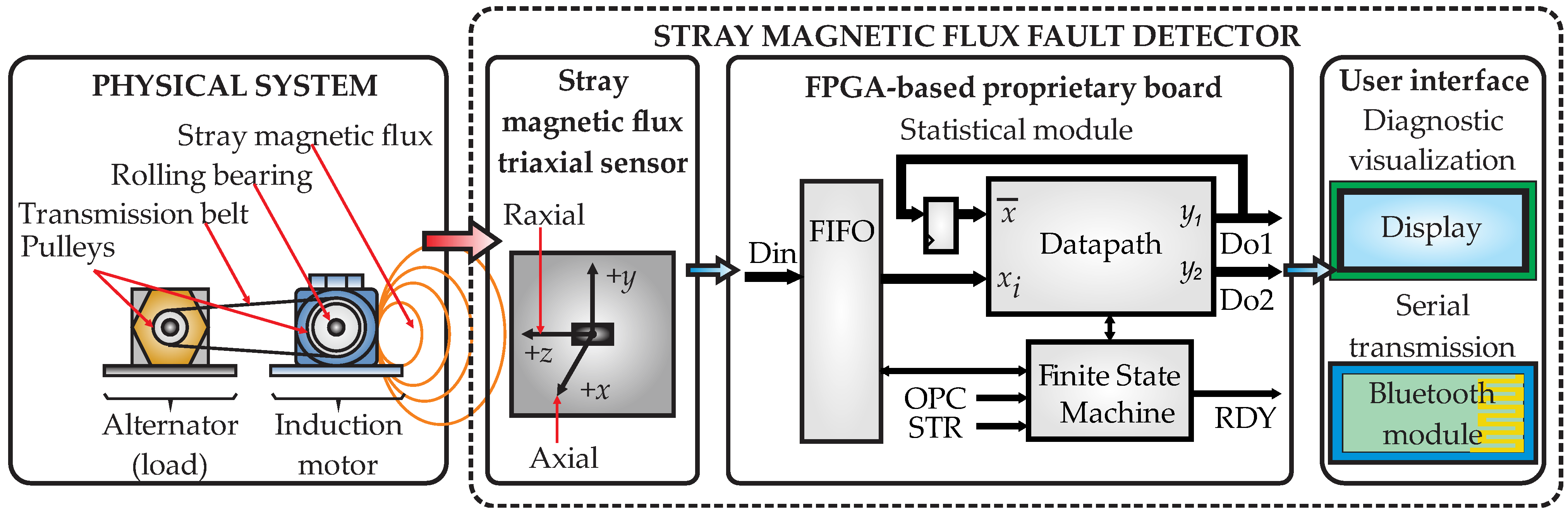
3. Proposed Fault Detector Based on FPGA and Stray Flux Applied on Bearings

In this section, the methodology followed for developing a dedicated system for diagnosing faults in rolling bearings (considering outer race faults according to the standard ISO 15243) of induction motors is described. The monitoring tool is implemented into an FPGA-based proprietary board making use of stray magnetic flux signals measured in the motor’s surroundings and by computing statistical indicators. Figure 1 presents a block diagram of this tool, named the stray magnetic flux fault detector (SMFFD), and the implementation can be revised in four main blocks: (i) physical system, (ii) stray magnetic flux triaxial sensor, (iii) statistical module implemented in the FPGA-based proprietary board, and (iv) user interface. As can be noted from the figure, the last three blocks integrate the SMFFD system.

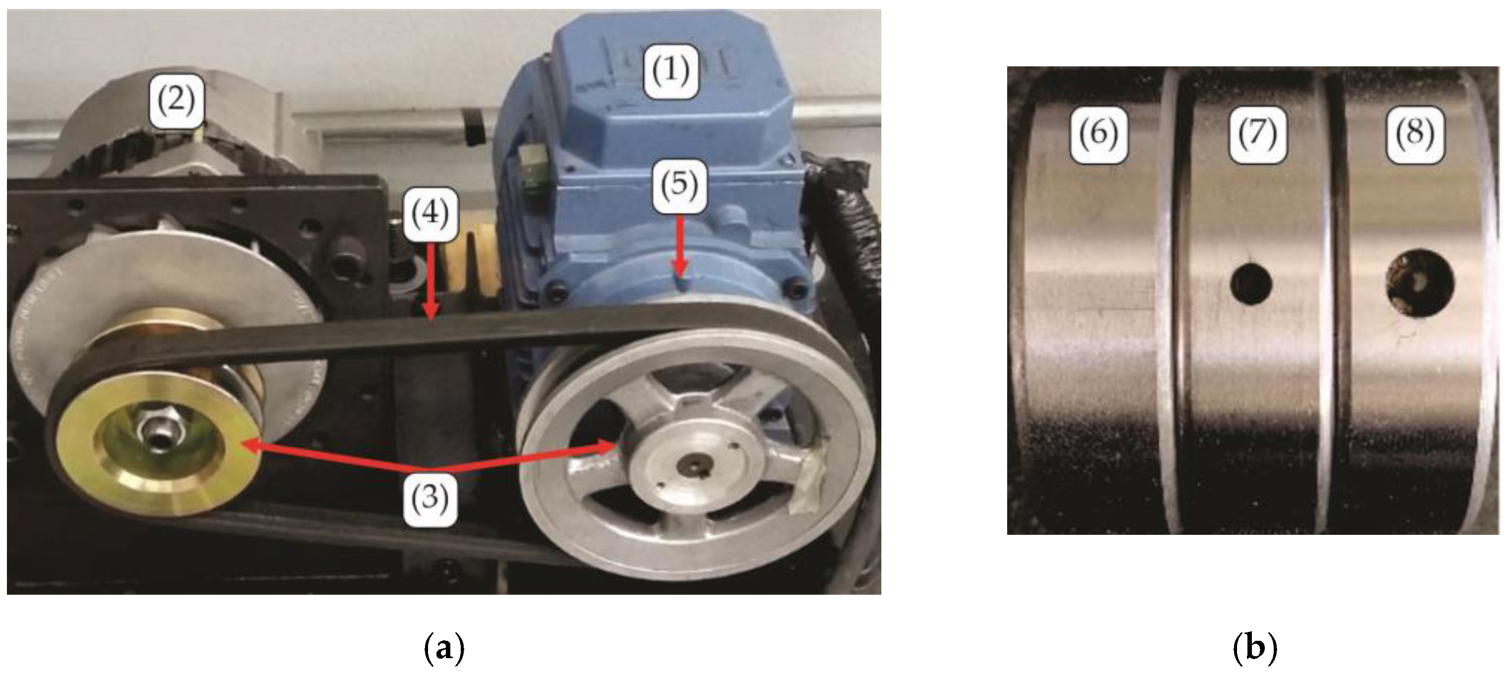
3.1. Physical System

From Figure 1, the first block of the proposed methodology is the physical system consisting of the electromechanical coupling between an induction motor and an automotive alternator used as the load. The coupling is performed through a transmission belt and two pulleys at the motor and alternator shafts. This way, the system will work under industrial operating conditions. Inside the motor, the rolling bearing under analysis supports the rotor frontal shaft, and during the experimental tests, this bearing is substituted by a bearing with its respective fault condition (healthy and fault conditions). As mentioned in the standard ISO 15243, faults in bearings are associated to different failure modes [37]. However, in this work, only those related with fracture and cracking affecting the outer race of the element were considered because of their statistical importance as reported in the literature. In addition, pitting is an outer race affectation due to the fact of electrical erosion, and this failure mode was also considered. Although these failure modes also consider the inner race affectations on bearings, this work begins by analyzing only outer race faults, with the purpose of keeping a simple structure and its online implementation. Nevertheless, the configurability of the proposed SMFFD could allow to expand its functionality, incorporate other sensors, compute and process additional data, and implement additional algorithms with the aim of detecting other types of faults. Thus, three standard steel bearings, model 6203 2RS, manufactured by SKF, with an external diameter of 40 mm, an internal diameter of 17 mm, and 8 caged balls were prepared for testing the conditions considered, i.e., healthy state and two fault conditions in the outer race with increasing severity. The preparation of the bearings is described as follow: The rubber seals were removed from the back of the bearings and the grease inside was completely cleaned with the help of solvents to remove any grease residue. Next, with the help of metallic clamps, the bearing was secured on the bed of a computerized numerical control (CNC) milling machine for drilling holes on the outer race of each bearing, generating the following fault cases: 3 mm hole (fault severity: 1) and 5 mm hole (fault severity: 2). Once the holes were drilled, an exhaustive cleaning was carried out by blowing compressed air into the bearing’s interior; in addition, some solvents were applied to avoid any type of burr that would prevent their correct operation. Finally, BATat-3 grease was applied, which is a high-quality bentone adhesive lubricant designed for the maintenance of bearings operating at high temperatures, and the rubber seals were placed again. The first experimental test used the healthy bearing, and posteriorly the bearing under analysis was changed to one with a fault severity of 1 and next by one with a fault severity of 2. The faults induced defined the controlled experimentations on the physical system, having as advantages the development of rapid tests, adequate and realistic fault design, and variations in the fault severity over short times with the desired graduality. For example, the outer race faults were easily and rapidly induced through a machining process with the desired gradual severity, without the need of waiting for long periods of time over physical system’s operation until a real failure occurs. As a counterpart, of course, induced faults cannot reflect the unpredictable ways in which a real fault may occur and affect the physical system. However, the system can be adjusted to be validated under tests of bearings with real faults because of its configurability. It must be clarified that induced faults are real damage to a bearing, and when it is mounted in a physical system, it causes, in consequence, a behavior different from that described with a healthy bearing.

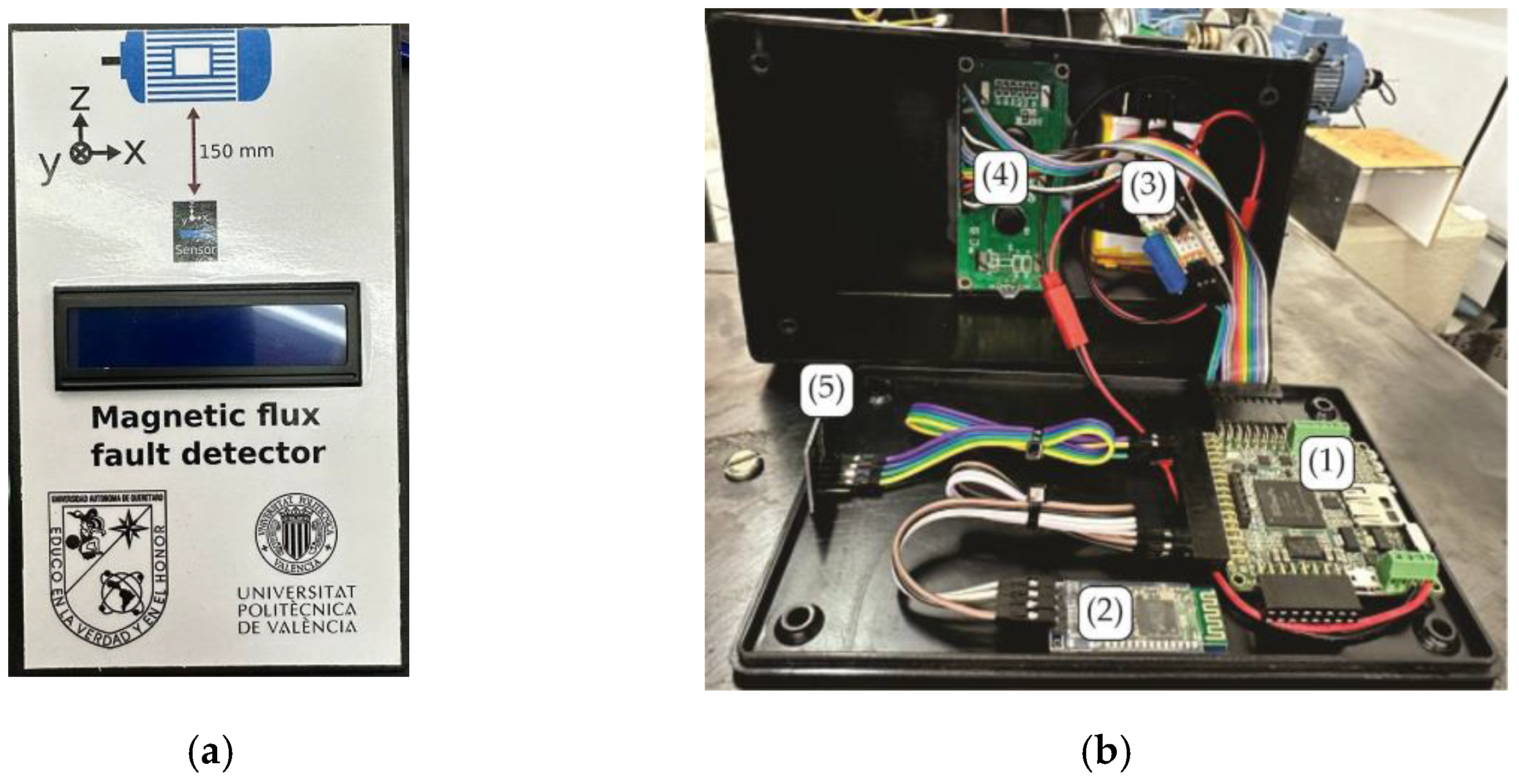
3.2. Stray Magnetic Flux Fault Detector

The second block of the proposed methodology, which is the first part of the SMFFD, is the stray magnetic flux triaxial sensor. Therefore, in order to put the use of the sensor in context, the following must first be mentioned. During the operation of the induction motor, using the healthy bearing, a stray magnetic flux is generated; thus, when this bearing suffers damage, the stray flux has variations in the field magnitude and can be measured. Consequently, a triaxial sensor measures such variations of the stray flux in the motor’s surroundings from sensor axes “x”, “y”, and “z”, which for this work corresponded to the axial, axial–radial, and radial directions, respectively. It is worth mentioning that the useful information that the stray magnetic flux can provide will depend on factors such as the element analyzed in the motor, the sensor’s placement, and the type of fault studied, among others. However, based on previous experimentations and reported works in the literature [41], axial direction measurement was considered in this work. Finally, the measured signal was sent to the digital system for data processing.

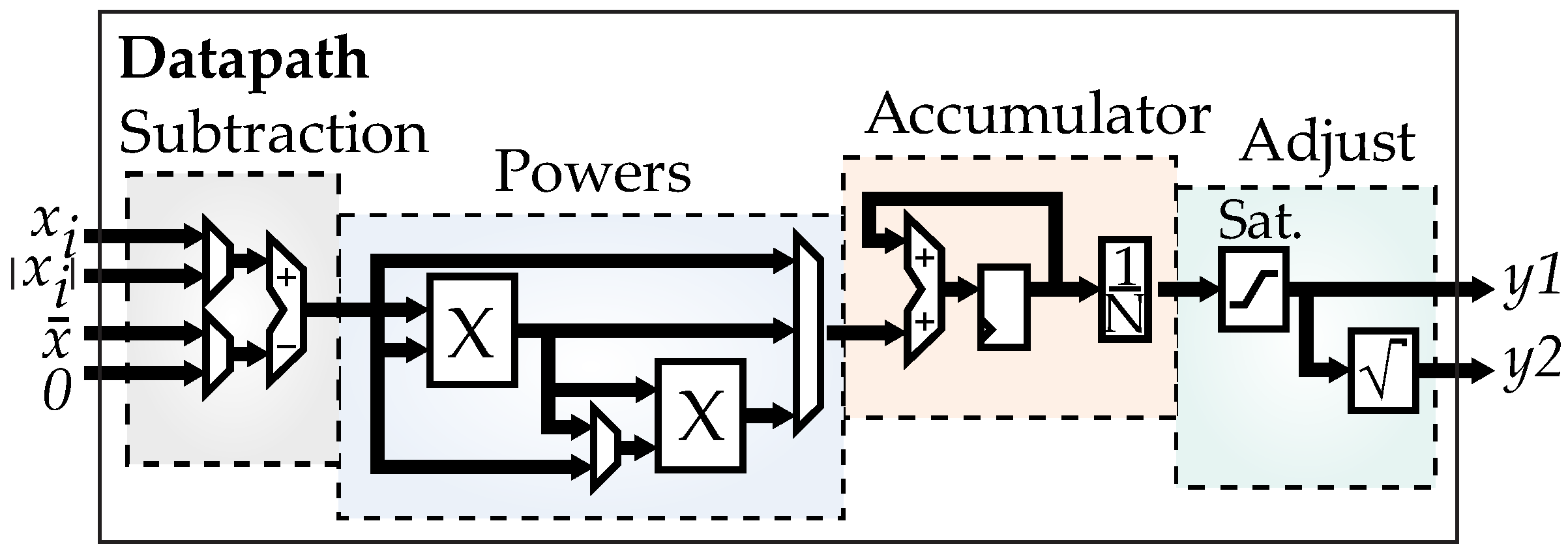
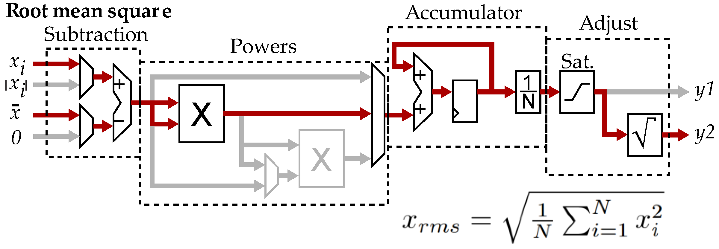
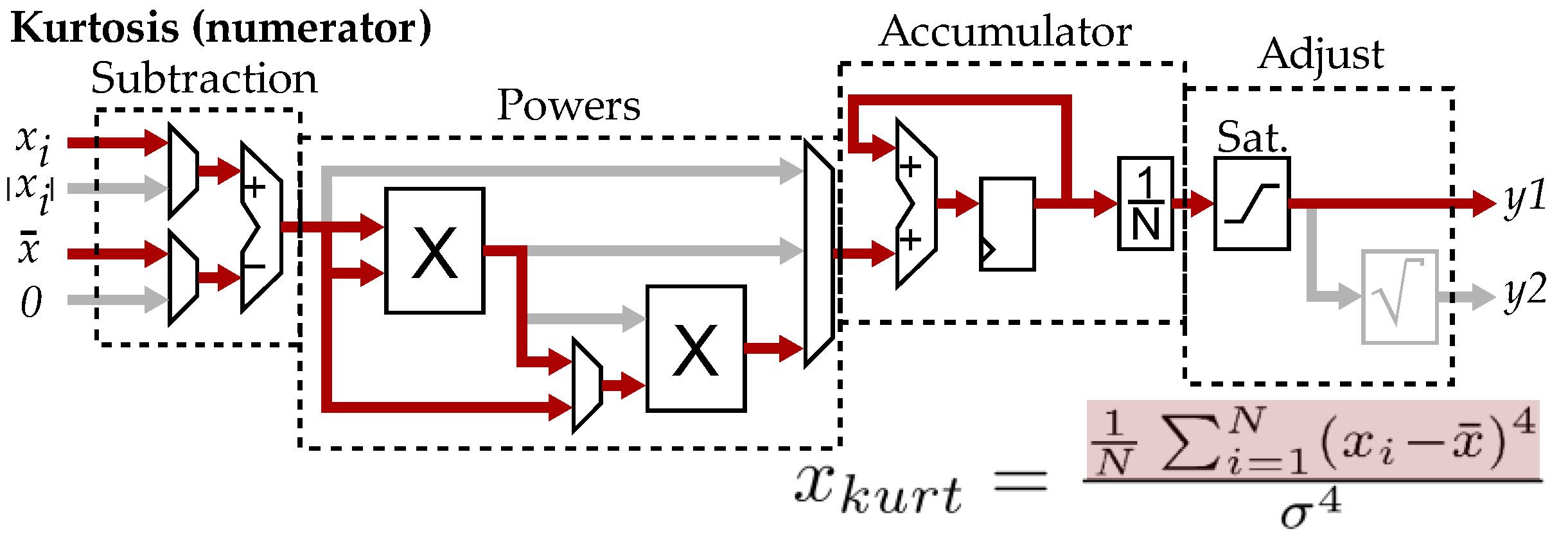
3.3. Statistical Module Implemented into the FPGA-Based Proprietary Board

The third block of the proposed methodology is the statistical module hardware architecture of the SMFFD, which uses the data acquired from the stray magnetic flux sensor to compute the statistical indicators through Equations (1)–(11), as shown in Table 2. To perform this task, the algorithms required in this module are implemented into the FPGA-based proprietary board. Therefore, the hierarchical architecture, developed through hardware description language (HDL), is integrated by the IPcores/soft-cores, such as the first-in, first-out (FIFO) memory, the datapath, a finite states machine (FSM), and pipeline registers. It must be said that the proprietary board implements an embedded processor to control all of the hardware architectures developed for this module and any module required. This embedded processor is not visible in the block diagram in Figure 1, but its function is to drive the data acquisition from the stray magnetic flux sensor, statistical module, and user interface (diagnostic visualization and serial transmission of data). For its part, the FIFO memory stores the input data vector (Din) of the measured signal to speed up the calculation. Meanwhile, the FSM drives the operation of the datapath module and regulates the input of the data from the FIFO. Hence, the embedded processor executes the following sequence, loads the input data to the FIFO memory, defines the operation that the datapath must perform through the OPC command (statistical feature required), and starts the operation process by means of a pulse in the STR terminal. Once the module finishes, it generates a pulse on the RDY terminal and the output data (i.e., result) can be read on terminals Do1 and Do2. In summary, the FSM has the purpose of synchronizing all calculations in case extra steps are required to deliver the expected result.
The main IPcore of the hardware architecture is the datapath, because the statistical features are obtained through this module. Figure 2 shows a simplified diagram of the internal structure of this function, which consists of four main stages: subtraction, powers, accumulator, and adjust. The subtraction stage determines whether the mean, x ¯ , must be subtracted from the input, x i , or if the absolute value, | x i | , is taken. The powers stage determines the power to which the result of the previous operation is raised, and the power values are 1, 2, 3, and 4. The accumulator stage performs the accumulation of the result of the powers module. For the case of the 1 N divisor, this operation is executed as a shift in the fixed-point representation, since N is always considered as an exact power of 2. The adjust stage carries out the rounding and saturation, if applicable, of the accumulated value, and it is the output y 1 ; in addition, if necessary, it applies the square root of the rounded result, and it is the output y 2 . It is important to mention that for every stage, pipeline registers are used with the objective of balancing the latency lines of the computational process.
All operations in the datapath IPcore are performed in a fixed-point format, which is specified in the presynthesis during IPcore instantiation, where the numerical representations are adjusted automatically during the elaboration process. In general, this hardware architecture requires two full word multipliers used in the powers stage and an additional one used by the square root unit, which is carried out through a successive approximations register (SAR). In addition, several adders/subtractors are required in the initial stage: accumulation and rounding. Moreover, another register is used for the accumulator and several multiplexers for routing the data flow. The implementation of the datapath considers the latency balance, where each combinational operation is isolated from the next by a pipeline register, which controls the combinational delays within the FPGA’s structure and maximizes the operation’s frequency. For the multipliers, a latency of 4 clock cycles was considered to maintain data coherence, and balancing registers were placed to synchronize the data paths parallel to the multipliers. Finally, for illustrative purposes and for the sake of not extending too much the explanation of the obtention of the statistical indicators, only two calculus chains are described: root mean square and kurtosis.
Therefore, by taking as the basis the general hardware structure in Figure 2 to calculate the root mean square and using Equation (3) in Table 2, Figure 3 shows the data flow, marked in red, selected by the FSM through the OPC command to obtain this value. From the figure, the calculus chain starts by subtracting the mean, x ¯ , to the input, x i , and this value is then raised to the power of 2, the result is accumulated and divided by N, the square root is obtained from the rounded value, and the output is in terminal y 2 . In this case, the powers stage considers a latency of 8 cycles to maintain datapath synchronization.
Similarly, using the previous example and considering the general diagram in Figure 2 and Equation (11) in the Table 2 to calculate the kurtosis, four steps are necessary: calculation of the mean, calculation of the standard deviation, calculation of the numerator of the kurtosis, and calculation of the kurtosis. Figure 4 shows the data flow, marked in red, to calculate the kurtosis numerator. For this purpose, two multipliers are used in the powers stage to obtain the fourth power term. The final kurtosis value is calculated through the firmware of the floating-point co-processor, in the hardware, by dividing the kurtosis numerator by the standard deviation raised to a power of 4.

3.4. User Interface

The last block of the proposed methodology is the user interface that presents a visualization of the diagnosis results through a liquid crystal display (LCD). In this LCD screen are displayed the statistical indicators obtained by the SMFFD system. Only those indicators that can provide useful information about the faults detected are displayed on the screen. It is worth mentioning that the user can extract the measured signal and the statistical indicators through an additional port of serial communication, since the system has IPcores to drive a Bluetooth module.

4. Results and Discussion

4.1. Experimental Setup

The experimental test bench is an electromechanical system consisting of the coupling between an induction motor and an automotive alternator. Figure 5a presents a picture of the experimental test bench. The characteristics of the induction machine are as follows: manufactured by WEG, triphasic motor, one pair of poles, case type A.E. 00136AP3E48TCT, rated power of 740 W, nominal speed of 3355 RPM, input voltage of 210-230/460 Vac, and operating frequency of 50/60 Hz. For its part, an automotive alternator was used as the mechanical load entailing approximately 30% of the motor capacity. All elements tested were standard steel bearings manufactured by SKF, model 6203 2RS, with an external diameter of 40 mm, internal diameter of 17 mm, and eight caged balls. The bearings’ preparation was described previously in Section 2. Figure 5b presents pictures of the bearings used after such preparation in the three conditions analyzed: healthy bearing and two bearings with severity levels 1 (3 mm hole) and 2 (5 mm hole). As mentioned, inside the motor the bearing under analysis supports the rotor frontal shaft, and during the experimental tests, this bearing is substituted by the bearings with their respective defined condition. According to the standard ISO 15243, these induced faults can be categorized as fractures and cracks but also as pitting phenomenon caused by electrical erosion. For the experimental trials, the electromechanical system was driven through a variable frequency driver (VFD) feeding the motor with a start ramp of 10 s, which was previously programmed, that reached a final operating frequency of 50 Hz. Taking into consideration this ramp, every trial lasted 40 s, with the first 10 s corresponding to the transient response and the last 30 s to the steady state. For the data processing in the SMFFD, only the steady state was considered. This way, a total of 15 runs per bearing condition (healthy state and two outer race severities) were carried out, generating 15 runs × 3 conditions = 45 data sets.

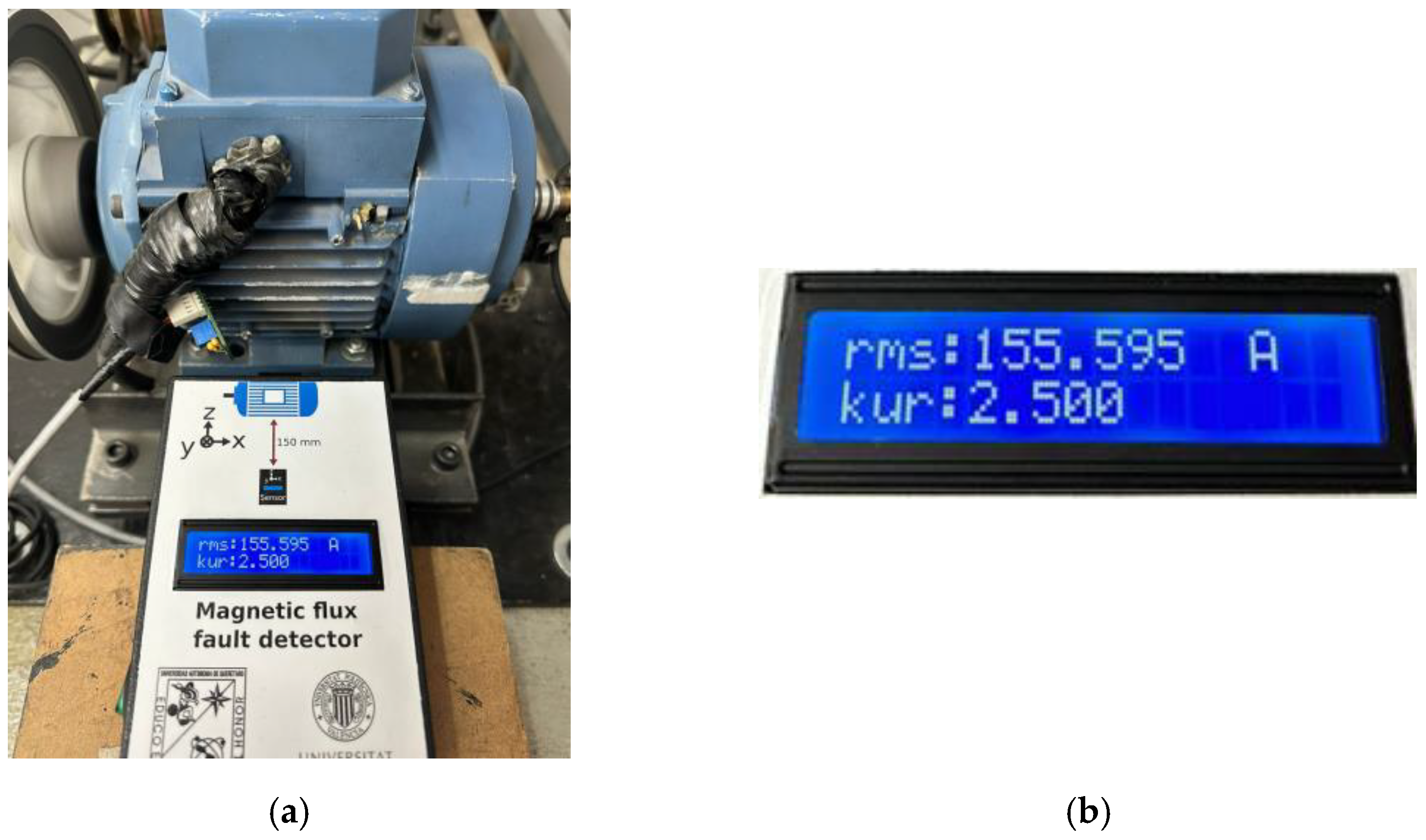
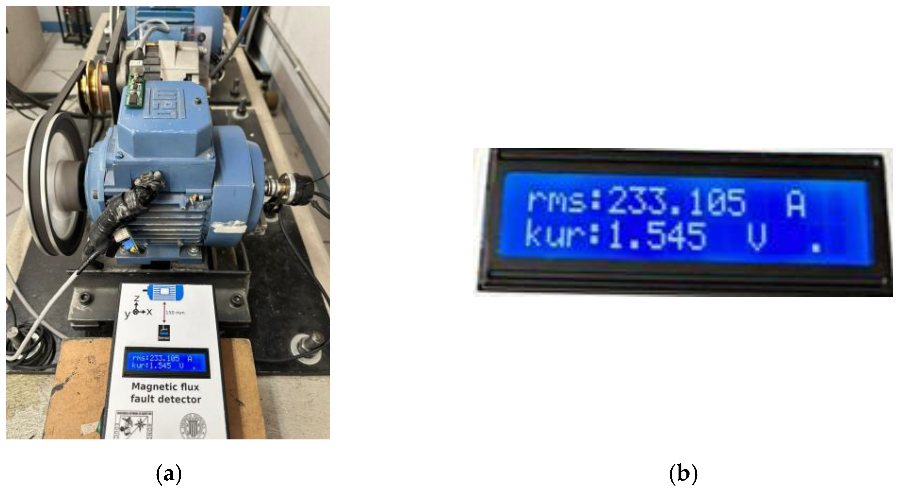
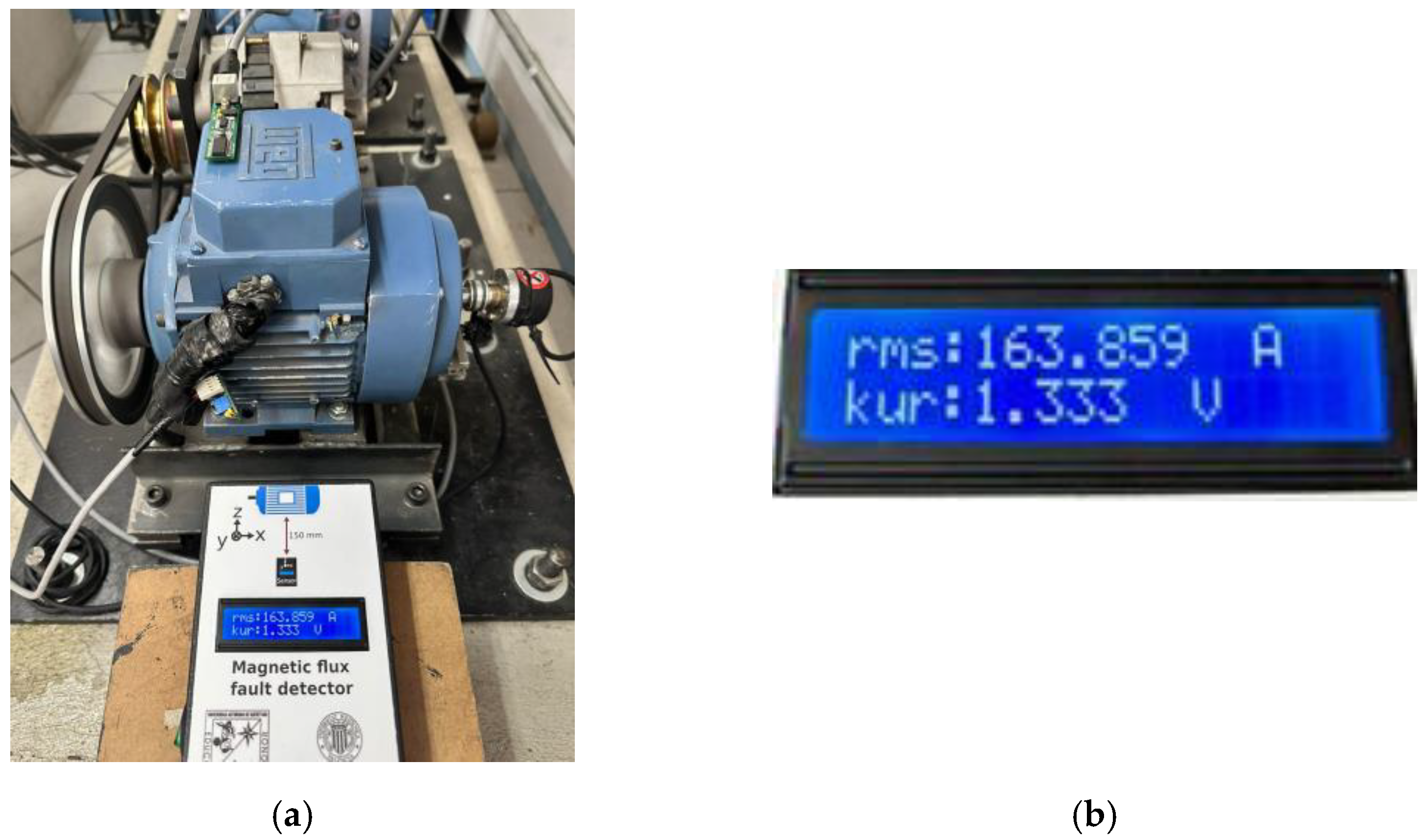
4.2. Stray Magnetic Flux Fault Detector

Regarding this tool developed, Figure 6a presents the physical SMFFD system for diagnosing bearings in induction motors. From the figure, it can be noted that in the final package’s presentation, only the LCD screen is visible to the user. A sticker indicates the way of placing the SMFFD in respect to the motor for a correct analysis; as previously mentioned, the axial flux (“x”-axis) was of interest [41]. Internally, as shown in Figure 6b, the box contains the FPGA-based proprietary board, Bluetooth module, power source, liquid crystal display, and triaxial stray magnetic flux sensor. For its part, the triaxial sensor for measuring the stray magnetic flux is the board BM1422AGMV-EVK-001 from ROHM Semiconductor manufacturer, and it was installed in the SMFFD box making the “x”-, “y”-, and “z”-axes coincident with the axial, axial–radial, and radial directions of the stray flux generated by the motor, respectively. These sensors had the following features: bandwidth of 1 kHz, I2C interface, sensitivity of 0.042 μ T / LSB , sensing range of ± 1200   μ T , and supply voltage of 1.7–3.6 V. The proprietary board characteristics were described previously in Section 3. In relation to the FPGA, the proposed IPcores were implemented as hardware processing units: inter-integrated circuit (I2C) communication for acquiring the data of the stray magnetic flux sensor, statistical module, LCD driver, communication port UART, and embedded system that comprises the processor, memory driver, ISB connection, and USB interface of the programming. Here, the firmware controls all modules for implementing fault detection through the stray magnetic flux.
The SMFFD performed the data acquisition from the sensor at a sampling frequency of 1 kHz, and the data of interest were in the steady state of the machine, as previously mentioned, in the last 30 s of each trial. For the computation of the statistical indicators time windows of 4086 data points were taken with overlaps between the windows of 50%. Therefore, every statistical indicator was obtained and updated approximately every two seconds during the online monitoring process. In this way, 29 indicators were generated per trial, 345 indicators per bearing condition, and a total of 1305 indicators for all three conditions, which were used for validating the diagnosis. The SMFFD monitoring tool indicates in the LCD the information regarding the final diagnosis through the values of the statistical indicators; for instance, on the screen two indicators per row are displayed. The fault severity is known according to a defined range of values to which the statistical indicators belong. Additionally, the measured signal and the statistical indicators can be extracted by the user through serial transmission of the Bluetooth module.
In summary, the Spartan 6 XC6SLX45 is a cost-optimized FPGA, according to the manufacturer, and the hardware resources used by the SMFFD system are presented in Table 3. The resources used consider all of the modules described previously (embedded processor, statistical module, drives for LCD and Bluetooth, etc.). From the table, the column “Logic utilization” refers to the specific hardware elements in the FPGA; the column “Used” indicates the exact number of implemented elements; the column “Available” indicates the total available of each type of element; and the column “Utilization” represents the percentage of elements used in respect to the total available. Finally, the tool for synthetizing the project was Xilinx ISE 14.7, using the Ubuntu 22.04 operating system.
In the case of IOBs, this refers to the physical terminals of the device, where most are IOs connected to external RAM (40 pins), and there are general purpose IOs (16 pins), the rest are connected to the LCD, sensor, communication ports, etc. In general, it can be said that a quarter of the device’s resources are used.

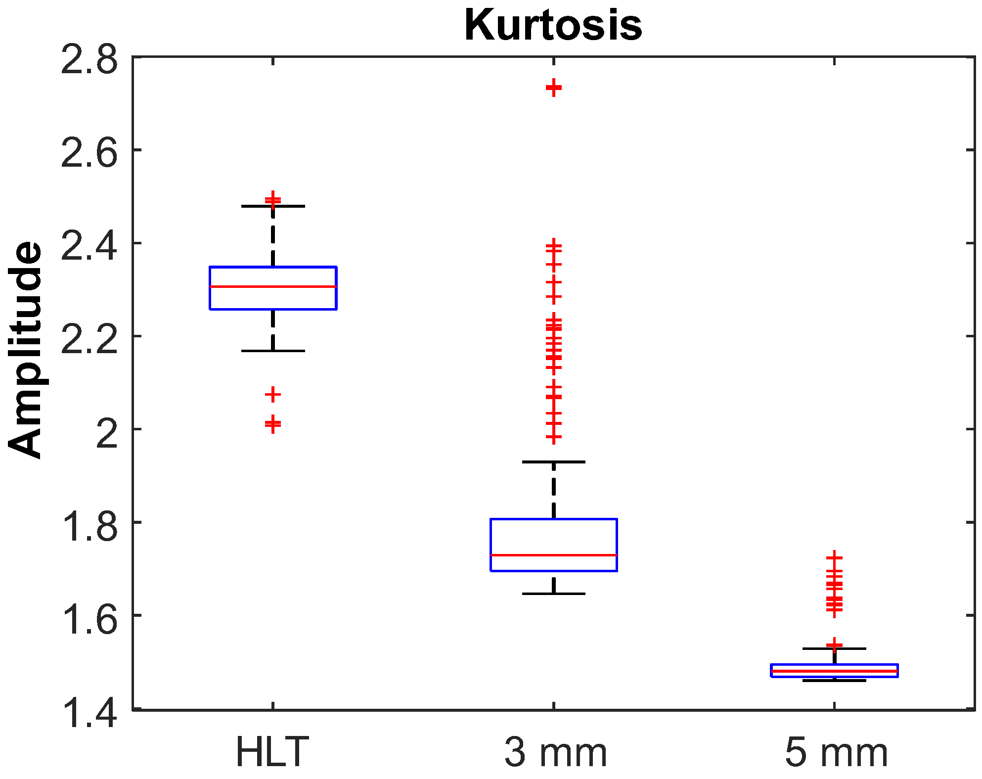
4.3. Results of the Fault Diagnosis through the SMFFD

In the next paragraphs, the fault diagnosis through the SMFFD is described. For performing the diagnosis task, thresholds must be defined as follows: The statistical features’ values vary in a range according to the bearing’s condition in the motor; for instance, the motor with a bearing fault and with a severity level will cause variations in the statistical values different from those when the motor bearing is healthy. Therefore, after several experimental trials, it was found that from the eleven statistical indicators only a few of them present meaningful information related to the fault and its severity; the rest have incipient variations in their values. For this work, the statistical indicators of the RMS and kurtosis provided the best information related to the fault and its severity. Thus, the RMS was used to provide a threshold of whether the kurtosis data were valid, because if the RMS was out of range, then the kurtosis was saturated. This range, which was experimentally defined, established the RMS amplitude between 150 and 250, which corresponds to measurements of the sensor between 5 μ T and 10 μ T , respectively. Thus, if the kurtosis values fell into this range, then data were valid, but for values outside of this range, the kurtosis would not be valid. Meanwhile, the kurtosis was used for defining a set of ranges for indicating the bearing’s condition. To obtain these kurtosis ranges, an independently short experimentation was carried out as follows: The stray magnetic flux signal was acquired in the time domain (1 kHz sampling frequency) at the steady state and a total of 140 time windows were used, each one of 4 s in length, for every bearing condition (healthy, 3 mm hole, and 5 mm hole). Therefore, 140 windows per three conditions resulted in 420 windows that were used to obtain the kurtosis boxplots for differentiating every bearing condition, see Figure 7.
Through the boxplots in Figure 7, it can be noted that on the “x”-axis the labels “HLT”, “3 mm”, and “5 mm” represent the bearing conditions healthy, severity 1, and severity 2, respectively. On the “y”-axis are the amplitude values that every boxplot spans. Congruently, the ranges that determine the severity of the faults are summarized in Table 4.
For the sake of validating the monitoring system’s functionality, the results of the three analyzed conditions are presented. Figure 8a shows an image of the SMFFD system performing online monitoring and diagnosis of the induction motor with a healthy state bearing (element without problems in the outer race) mounted in the rotor’s frontal shaft. From the picture, it can be observed that the placement of the SMFFD in relation to the induction motor was nonintrusive, because the SMFFD stayed in the surroundings of the physical system. Meanwhile, Figure 8b presents a digital zoom in on the SMFFD focused on the LCD screen to better appreciate the results obtained from the fault diagnosis. From this zoom, the statistical indicators shown to the user are the RMS and kurtosis, having magnitudes of 155.595 (kurtosis is a valid value) and 2.5, respectively. Therefore, by taking the value of the kurtosis and comparing it with the ranges in Table 4, the diagnosis is a healthy bearing. The letter “A” that appears on the LCD screen next to the RMS value is not an indication of units, instead this letter indicates that the SMFFD system is performing the analysis. Additionally, the letter “V” appears next to the value of the kurtosis, and this letter indicates that a fault condition was detected. It is worth highlighting, again, the practicality of the monitoring tool because it has the following advantages: it is a nonintrusive system (the sensor in the SMFFD measures the stray magnetic flux in the motor’s surroundings), the fault diagnosis is completely online, the system is portable, its reconfigurability, and the functionality expansion.
In another case, Figure 9a presents a captured image of the SMFFD system performing online monitoring and diagnosis of the induction motor with a bearing, mounted in the rotor’s frontal shaft, having the severity of 1 for an outer race fault (hole of 3 mm). At the same time, Figure 9b presents a digital zoom of the LCD screen for this case, indicating an RMS with a value of 233.105 (kurtosis is a valid value) and the kurtosis with a value of 1.545. Hence, by taking the value of the kurtosis and comparing it with the ranges in Table 4, the diagnosis is effectively the outer race fault on the bearing with a hole of 3 mm.
Figure 10a depicts a photograph of the SMFFD system performing online monitoring and diagnosis of the induction motor with a bearing, mounted in the rotor’s frontal shaft, having the severity of 2 for an outer race fault (hole of 5 mm). Figure 10b shows a digital zoom on the screen of the tool indicating magnitudes for the RMS of 163.859 (kurtosis is a valid value) and a magnitude for the kurtosis of 1.333. Therefore, by taking the value of the kurtosis and comparing it with the ranges in Table 4, the diagnosis is an outer race fault on the bearing with a hole of 5 mm.

5. Conclusions

This work presents a methodology for developing an online monitoring tool for diagnosing outer race faults on bearings in induction motors. The monitoring tool, named the stray magnetic flux fault detector, was developed into an FPGA-based proprietary board, performing an analysis on the data from the acquired stray magnetic flux signal. The are several advantages to using an FPGA-based solution, for example, the design in the hardware for faster data processing, concurrent execution of the IPcores, configurability, portability, functionality expansion according to the application requirements, and high operational frequency, among others. The practicality of the developed tool is observed in its compact design following an all-in-one philosophy, which means that the system includes the FPGA, an embedded processor, the sensor, the user interface, and the power source. Therefore, the user must only put the system near to the induction motor that needs to be analyzed, and the online fault diagnosis will be performed. This is achieved thanks to the sensor integrated into the system’s box, thus measuring the stray magnetic flux from three directions (axial, radial, and axial–radial) in the motor’s surroundings, making the system nonintrusive. Now, in relation to the FPGA potential, the implementation of the IPcore for the calculation of the statistical indicators demonstrates the powerfulness of the programmable logic device, because the system acquires the physical signal and extracts the features related to the faults. As mentioned, the selection of the statistical features is because they are relatively easy to compute and can provide nonvisible information about the data distribution. In this sense, the calculation of the statistical indicators was performed through a generalized hardware architecture in only four stages. It is worth mentioning the potential of computing diverse statistical indicators, for this work from the set of statistical features, two of which became meaningful in the final diagnosis. The RMS validates the kurtosis value and this allows for the differentiation of the bearing conditions; thus, the system is based on these two features. However, if other types of faults need to be analyzed, the rest of the statistical features could be helpful, since the faults could be reflected as different symptoms in the physical system and, consequently, in the acquired data. Thus, the calculation of several statistical indicators is important, because they could be useful for the analysis of other types of faults. In addition, in future work other nonstatistical indicators can be computed and explored for developing fault detection methodologies. Finally, as mentioned, the developed system has an interesting and important characteristic which is the configurability allowing for the inclusion of extra IPcores, allowing the system to be adjusted as required. For this reason, the system is able to be expanded in functionality and with the possibility of being explored for other monitoring applications, because other types of sensors can be added and other hardware structures can be described according to an application’s requirements.

Author Contributions

Conceptualization, R.A.O.-R. and J.A.A.-D.; methodology, L.M.-V.; software, L.M.-V.; validation, J.C.-O. and I.Z.-R.; formal analysis, J.C.-O.; investigation, A.Y.J.-C.; data curation, J.C.-O. and I.Z.-R.; writing—original draft preparation, A.Y.J.-C. and L.M.-V.; writing—review and editing, A.Y.J.-C.; visualization, R.A.O.-R.; supervision, R.A.O.-R. and J.A.A.-D.; project administration, J.A.A.-D.; funding acquisition, J.A.A.-D. All authors have read and agreed to the published version of the manuscript.

Funding

This research was funded by the Spanish “Ministerio de Ciencia e Innovación”, Agencia Estatal de Investigación and FEDER program in the framework of the “Proyectos de Generación de Conocimiento 2021” of the “Programa Estatal para Impulsar la Investigación Científico-Técnica y su Transferencia”, belonging to the “Plan Estatal de Investigación Científica, Técnica y de Innovación 2021-2023” (ref: PID2021-122343OB-I00).

Data Availability Statement

Not applicable.

Acknowledgments

CONACyT scholarship.

Conflicts of Interest

The authors declare no conflict of interest.

References

  1. Melo, A.; Câmara, M.M.; Clavijo, N.; Pinto, J.C. Open Benchmarks for Assessment of Process Monitoring and Fault Diagnosis Techniques: A Review and Critical Analysis. Comput. Chem. Eng. 2022, 165, 107964. [Google Scholar] [CrossRef]
  2. Tidriri, K.; Chatti, N.; Verron, S.; Tiplica, T. Bridging Data-Driven and Model-Based Approaches for Process Fault Diagnosis and Health Monitoring: A Review of Researches and Future Challenges. Annu. Rev. Control 2016, 42, 63–81. [Google Scholar] [CrossRef]
  3. Geng, S.; Wang, X. Predictive Maintenance Scheduling for Multiple Power Equipment Based on Data-Driven Fault Prediction. Comput. Ind. Eng. 2022, 164, 107898. [Google Scholar] [CrossRef]
  4. Entezami, M.; Hillmansen, S.; Weston, P.; Papaelias, M.P. Fault Detection and Diagnosis within a Wind Turbine Mechanical Braking System Using Condition Monitoring. Renew. Energy 2012, 47, 175–182. [Google Scholar] [CrossRef]
  5. Cheshmeh, Z.A.; Bigverdi, Z.; Eqbalpour, M.; Kowsari, E.; Ramakrishna, S.; Gheibi, M. A Comprehensive Review of Used Electrical and Electronic Equipment Management with a Focus on the Circular Economy-Based Policy-Making. J. Clean. Prod. 2023, 389, 136132. [Google Scholar] [CrossRef]
  6. Dong, L.; Liu, S.; Zhang, H. A Method of Anomaly Detection and Fault Diagnosis with Online Adaptive Learning under Small Training Samples. Pattern Recognit. 2017, 64, 374–385. [Google Scholar] [CrossRef]
  7. Seera, M.; Lim, C.P.; Ishak, D.; Singh, H. Offline and Online Fault Detection and Diagnosis of Induction Motors Using a Hybrid Soft Computing Model. Appl. Soft Comput. 2013, 13, 4493–4507. [Google Scholar] [CrossRef]
  8. Hajoary, P.K. Industry 4.0 Maturity and Readiness- A Case of a Steel Manufacturing Organization. Procedia Comput. Sci. 2023, 217, 614–619. [Google Scholar] [CrossRef]
  9. Mykoniatis, K. A Real-Time Condition Monitoring and Maintenance Management System for Low Voltage Industrial Motors Using Internet-of-Things. Procedia Manuf. 2020, 42, 450–456. [Google Scholar] [CrossRef]
  10. Ghosh, P.K.; Sadhu, P.K.; Basak, R.; Sanyal, A. Energy Efficient Design of Three Phase Induction Motor by Water Cycle Algorithm. Ain Shams Eng. J. 2020, 11, 1139–1147. [Google Scholar] [CrossRef]
  11. Boteler, R.; Malinowski, J. Review of Upcoming Changes to Global Motor Efficiency Regulations. In Proceedings of the Conference Record of 2009 Annual Pulp and Paper Industry Technical Conference, Birmingham, AL, USA, 21–26 June 2009; pp. 26–30. [Google Scholar]
  12. Gangsar, P.; Tiwari, R. Signal Based Condition Monitoring Techniques for Fault Detection and Diagnosis of Induction Motors: A State-of-the-Art Review. Mech. Syst. Signal Process. 2020, 144, 106908. [Google Scholar] [CrossRef]
  13. Hakim, M.; Omran, A.A.B.; Ahmed, A.N.; Al-Waily, M.; Abdellatif, A. A Systematic Review of Rolling Bearing Fault Diagnoses Based on Deep Learning and Transfer Learning: Taxonomy, Overview, Application, Open Challenges, Weaknesses and Recommendations. Ain Shams Eng. J. 2023, 14, 101945. [Google Scholar] [CrossRef]
  14. Kumar, P.; Kumar, P.; Hati, A.S.; Kim, H.S. Deep Transfer Learning Framework for Bearing Fault Detection in Motors. Mathematics 2022, 10, 4683. [Google Scholar] [CrossRef]
  15. Gao, Y.; Yu, D. Fault Diagnosis of Rolling Bearing Based on Laplacian Regularization. Appl. Soft Comput. 2021, 111, 107651. [Google Scholar] [CrossRef]
  16. Jayakanth, J.J.; Chandrasekaran, M.; Pugazhenthi, R. Impulse Excitation Analysis of Material Defects in Ball Bearing. Mater. Today Proc. 2021, 39, 717–724. [Google Scholar] [CrossRef]
  17. Wen, C.; Meng, X.; Fang, C.; Gu, J.; Xiao, L.; Jiang, S. Dynamic Behaviors of Angular Contact Ball Bearing with a Localized Surface Defect Considering the Influence of Cage and Oil Lubrication. Mech. Mach. Theory 2021, 162, 104352. [Google Scholar] [CrossRef]
  18. Saxena, M.; Bannet, O.O.; Gupta, M.; Rajoria, R.P. Bearing Fault Monitoring Using CWT Based Vibration Signature. Procedia Eng. 2016, 144, 234–241. [Google Scholar] [CrossRef]
  19. Del Rosario Bautista-Morales, M.; Patiño-López, L.D. Acoustic Detection of Bearing Faults through Fractional Harmonics Lock-in Amplification. Mech. Syst. Signal Process. 2023, 185, 109740. [Google Scholar] [CrossRef]
  20. Zhiyi, H.; Haidong, S.; Xiang, Z.; Yu, Y.; Junsheng, C. An Intelligent Fault Diagnosis Method for Rotor-Bearing System Using Small Labeled Infrared Thermal Images and Enhanced CNN Transferred from CAE. Adv. Eng. Inform. 2020, 46, 101150. [Google Scholar] [CrossRef]
  21. Zhang, J.; Sun, Y.; Guo, L.; Gao, H.; Hong, X.; Song, H. A New Bearing Fault Diagnosis Method Based on Modified Convolutional Neural Networks. Chin. J. Aeronaut. 2020, 33, 439–447. [Google Scholar] [CrossRef]
  22. Ruan, D.; Wang, J.; Yan, J.; Gühmann, C. CNN Parameter Design Based on Fault Signal Analysis and Its Application in Bearing Fault Diagnosis. Adv. Eng. Inform. 2023, 55, 101877. [Google Scholar] [CrossRef]
  23. An, Z.; Li, S.; Wang, J.; Jiang, X. A Novel Bearing Intelligent Fault Diagnosis Framework under Time-Varying Working Conditions Using Recurrent Neural Network. ISA Trans. 2020, 100, 155–170. [Google Scholar] [CrossRef] [PubMed]
  24. Luo, S.; Huang, X.; Wang, Y.; Luo, R.; Zhou, Q. Transfer Learning Based on Improved Stacked Autoencoder for Bearing Fault Diagnosis. Knowl.-Based Syst. 2022, 256, 109846. [Google Scholar] [CrossRef]
  25. Liu, S.; Jiang, H.; Wu, Z.; Li, X. Rolling Bearing Fault Diagnosis Using Variational Autoencoding Generative Adversarial Networks with Deep Regret Analysis. Measurement 2021, 168, 108371. [Google Scholar] [CrossRef]
  26. Kang, M.; Kim, J.; Kim, J.-M. An FPGA-Based Multicore System for Real-Time Bearing Fault Diagnosis Using Ultrasampling Rate AE Signals. IEEE Trans. Ind. Electron. 2015, 62, 2319–2329. [Google Scholar] [CrossRef]
  27. Magyari, A.; Chen, Y. Review of State-of-the-Art FPGA Applications in IoT Networks. Sensors 2022, 22, 7496. [Google Scholar] [CrossRef]
  28. Lopez-Ramirez, M.; Ledesma-Carrillo, L.M.; Rodriguez-Donate, C.; Miranda-Vidales, H.; Mata-Chavez, R.I.; Cabal-Yepez, E. FPGA-Based Online Voltage/Current Swell Segmentation and Measurement. Comput. Electr. Eng. 2023, 107, 108620. [Google Scholar] [CrossRef]
  29. Mitra, J.; Nayak, T.K. An FPGA-Based Phase Measurement System. IEEE Trans. Very Large Scale Integr. VLSI Syst. 2018, 26, 133–142. [Google Scholar] [CrossRef]
  30. Alcaín, E.; Fernández, P.R.; Nieto, R.; Montemayor, A.S.; Vilas, J.; Galiana-Bordera, A.; Martinez-Girones, P.M.; Prieto-de-la-Lastra, C.; Rodriguez-Vila, B.; Bonet, M.; et al. Hardware Architectures for Real-Time Medical Imaging. Electronics 2021, 10, 3118. [Google Scholar] [CrossRef]
  31. Saidi, A.; Ben Othman, S.; Dhouibi, M.; Ben Saoud, S. FPGA-Based Implementation of Classification Techniques: A Survey. Integration 2021, 81, 280–299. [Google Scholar] [CrossRef]
  32. Seng, K.P.; Lee, P.J.; Ang, L.M. Embedded Intelligence on FPGA: Survey, Applications and Challenges. Electronics 2021, 10, 895. [Google Scholar] [CrossRef]
  33. De la Piedra, A.; Braeken, A.; Touhafi, A. Sensor Systems Based on FPGAs and Their Applications: A Survey. Sensors 2012, 12, 12235–12264. [Google Scholar] [CrossRef]
  34. Mihalič, F.; Truntič, M.; Hren, A. Hardware-in-the-Loop Simulations: A Historical Overview of Engineering Challenges. Electronics 2022, 11, 2462. [Google Scholar] [CrossRef]
  35. Ezilarasan, M.R.; Britto Pari, J.; Leung, M.-F. Reconfigurable Architecture for Noise Cancellation in Acoustic Environment Using Single Multiply Accumulate Adaline Filter. Electronics 2023, 12, 810. [Google Scholar] [CrossRef]
  36. Bearing Failure and How to Prevent It|SKF. Available online: https://www.skf.com/us/products/rolling-bearings/bearing-failure-and-how-to-prevent-it (accessed on 13 March 2023).
  37. ISO 15243:2017(En); Rolling Bearings—Damage and Failures—Terms, Characteristics and Causes. ISO 2017, Technical Committee ISO/TC 4 Rolling bearings. Available online: https://www.iso.org/obp/ui/#iso:std:iso:15243:ed-2:v1:en (accessed on 13 March 2023).
  38. Alfredo Osornio-Rios, R.; Yosimar Jaen-Cuellar, A.; Ivan Alvarado-Hernandez, A.; Zamudio-Ramirez, I.; Armando Cruz-Albarran, I.; Alfonso Antonino-Daviu, J. Fault Detection and Classification in Kinematic Chains by Means of PCA Extraction-Reduction of Features from Thermographic Images. Measurement 2022, 197, 111340. [Google Scholar] [CrossRef]
  39. Jaen-Cuellar, A.Y.; Trejo-Hernández, M.; Osornio-Rios, R.A.; Antonino-Daviu, J.A. Gear Wear Detection Based on Statistic Features and Heuristic Scheme by Using Data Fusion of Current and Vibration Signals. Energies 2023, 16, 948. [Google Scholar] [CrossRef]
  40. Clemente-Lopez, D.; Rangel-Magdaleno, J.J.; Munoz-Pacheco, J.M.; Morales-Velazquez, L. A Comparison of Embedded and Non-Embedded FPGA Implementations for Fractional Chaos-Based Random Number Generators. J. Ambient Intell. Hum. Comput. 2022. [Google Scholar] [CrossRef]
  41. Vitek, O.; Janda, M.; Hajek, V.; Bauer, P. Detection of Eccentricity and Bearings Fault Using Stray Flux Monitoring. In Proceedings of the 8th IEEE Symposium on Diagnostics for Electrical Machines, Power Electronics & Drives, Bologna, Italy, 5–8 September 2011; pp. 456–461. [Google Scholar]
Figure 1. Block diagram of the methodology for detecting faults in the outer race of rolling bearings through the SMFFD.
Electronics 12 01924 g001
Figure 2. General hardware architecture of the datapath IPcore.
Electronics 12 01924 g002
Figure 3. Calculus chain to obtain the root mean square of Equation (3).
Electronics 12 01924 g003
Figure 4. Calculus chain to obtain the kurtosis numerator of Equation (11).
Electronics 12 01924 g004
Figure 5. Experimental setup: (a) test bench; (b) rolling bearings conditions. The considered elements were the (1) induction motor, (2) alternator as the motor load, (3) output shaft pulleys, (4) transmission belt, (5) location of the bearing under analysis in the frontal support of the shaft, (6) bearing with a healthy outer race, (7) bearing with a 3 mm hole in the outer race, and (8) bearing with a 5 mm hole in the outer race.
Electronics 12 01924 g005
Figure 6. FPGA-based proprietary SMFD: (a) physical system; (b) hardware components. The hardware components of the SMFD are the (1) FPGA-based proprietary board, (2) Bluetooth module, (3) power source, (4) liquid crystal display, and (5) proprietary triaxial stray magnetic flux sensor.
Electronics 12 01924 g006
Figure 7. Boxplots that determine the range of kurtosis for every condition of the bearing.
Electronics 12 01924 g007
Figure 8. (a) SMFFD performing an online fault diagnosis on the induction motor with the healthy bearing; (b) observing the results in detail through the digital zoom on the LCD screen.
Electronics 12 01924 g008
Figure 9. (a) SMFFD performing an online fault diagnosis on the induction motor with the bearing having a fault severity of 1 (3 mm); (b) observing the results in detail through the digital zoom of the LCD screen.
Electronics 12 01924 g009
Figure 10. (a) SMFFD performing an online fault diagnosis on the induction motor with the bearing having a fault severity of 2 (5 mm); (b) observing the results in detail through the digital zoom of the LCD screen.
Electronics 12 01924 g010
Table 1. Damage and failures in rolling bearings according to ISO 15243 [37].
Failure ModeFailure Subtype
FatigueSubsurface initiated fatigue
Surface initiated fatigue
WearAbrasive wear
Adhesive wear
CorrosionMoisture corrosion
Frictional corrosion
Electrical erosion 1Excessive current erosion
Current leakage erosion
Plastic deformationOverload deformation
Indentations from debris
Fracture and cracking 1Forced fracture
Fatigue fracture
Thermal cracking
1 Failure modes addressed in this work.
Table 2. Statistical indicators adopted for this analysis.
FeatureEquation
Mean x ¯ = 1 N · i = 1 N ( x i ) (1)
Mean of absolutes x ¯ a = 1 N · i = 1 N | x i | (2)
Root mean square x r m s = 1 N · i = 1 N ( x i ) 2 (3)
Standard deviation σ = 1 N · i = 1 N ( x i x ¯ ) 2 (4)
Variance σ 2 = 1 N · i = 1 N ( x i x ¯ ) 2 (5)
RMS shape factor S F r m s = x r m s x ¯ a (6)
Maximum value x p = m a x | x i | (7)
Crest factor x C F = x p x r m s (8)
Impulse factor x I F = x p x ¯ a (9)
Skewness 1 x s k e w = 1 N i = 1 N ( x i x ¯ ) 3 σ 3 (10)
Kurtosis 1 x k u r t = 1 N i = 1 N ( x i x ¯ ) 4 σ 4 (11)
1 High-order moments.
Table 3. Hardware resources of the Spartan 6 XC6SLX45 FPGA used by the SMFFD system.
Logic UtilizationUsedAvailableUtilization
Number of slice registers540154,5769%
Number of slice look up tables (LUTs)736727,28826%
Number of bonded input–output blocks (IOBs)10321847%
Number of block random access memory (RAM)/the first-in, first-out (FIFO)1711614%
Number of digital signal processing multipliers (DSP48A1s)145824%
Table 4. Ranges for condition detection according to the kurtosis statistical indicator.
Bearing ConditionKurtosis Range
Healthy state (HLT)[2.2–2.5]
Fault severity 1—Hole of 3 mm diameter[1.5–1.9]
Fault severity 2—Hole of 5 mm diameter[1.3–1.5]
Disclaimer/Publisher’s Note: The statements, opinions and data contained in all publications are solely those of the individual author(s) and contributor(s) and not of MDPI and/or the editor(s). MDPI and/or the editor(s) disclaim responsibility for any injury to people or property resulting from any ideas, methods, instructions or products referred to in the content.

