
Thermal Analysis of a Modular Permanent Magnet Machine under Open-Circuit Fault with Asymmetric Temperature Distribution

Abstract
:1. Introduction
2. Thermal Analysis Model
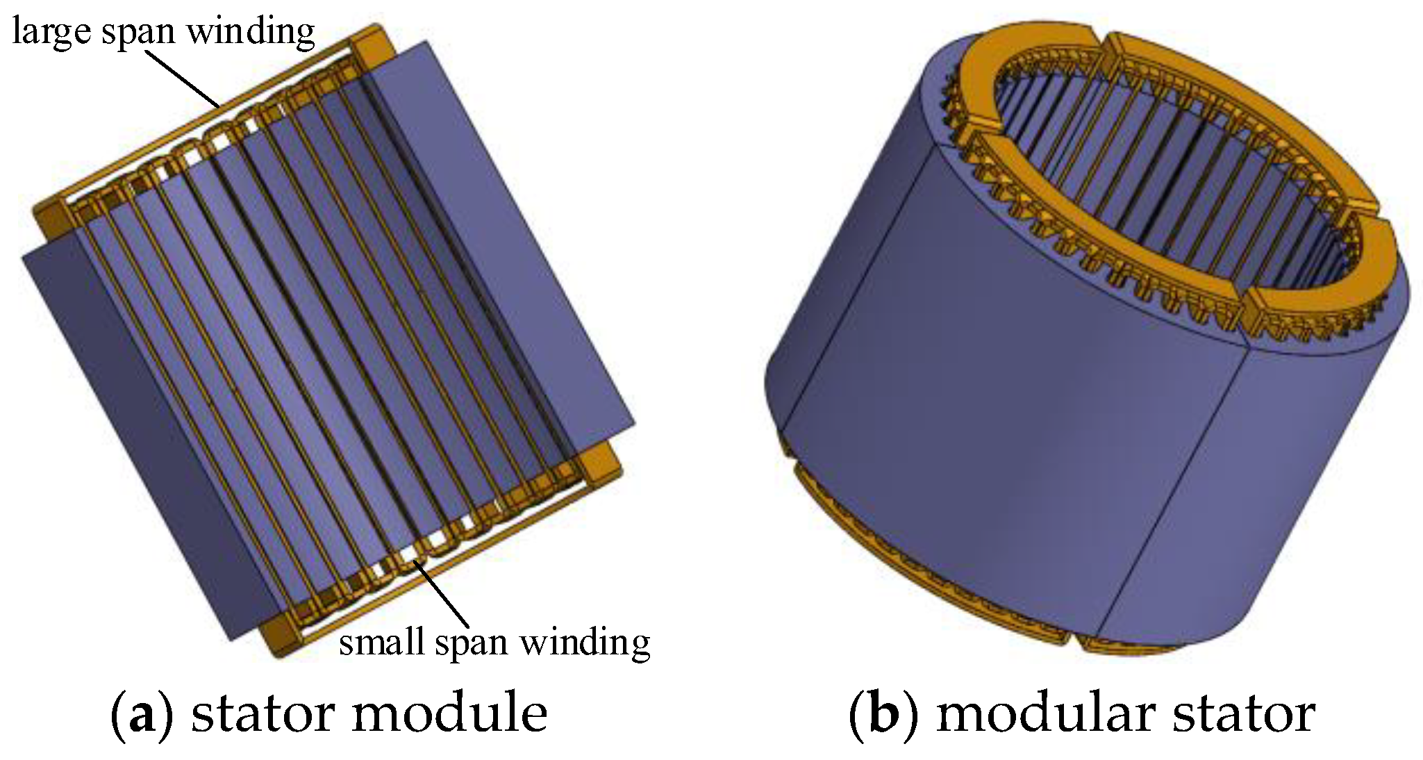
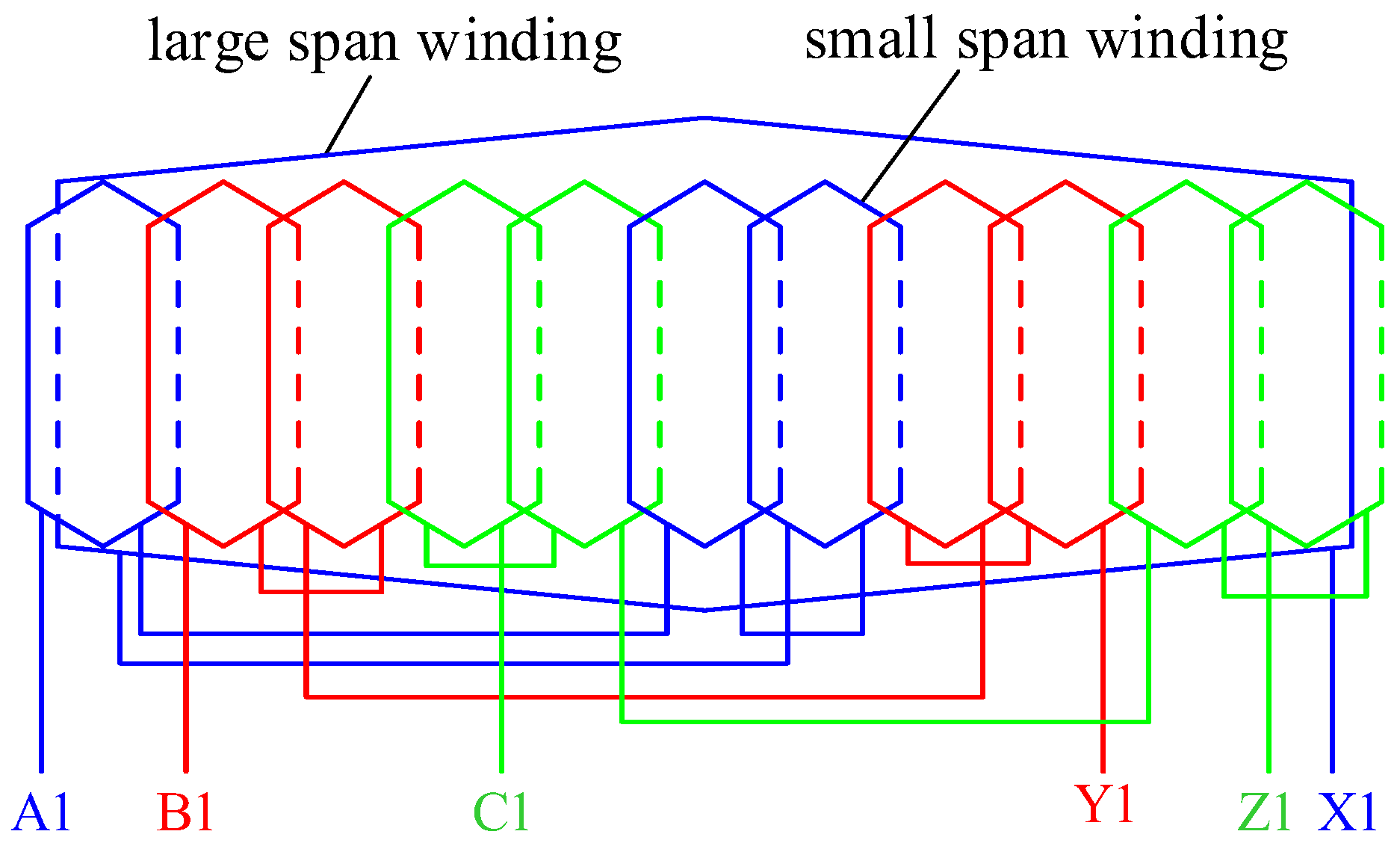
2.1. Structure of Modular Stator
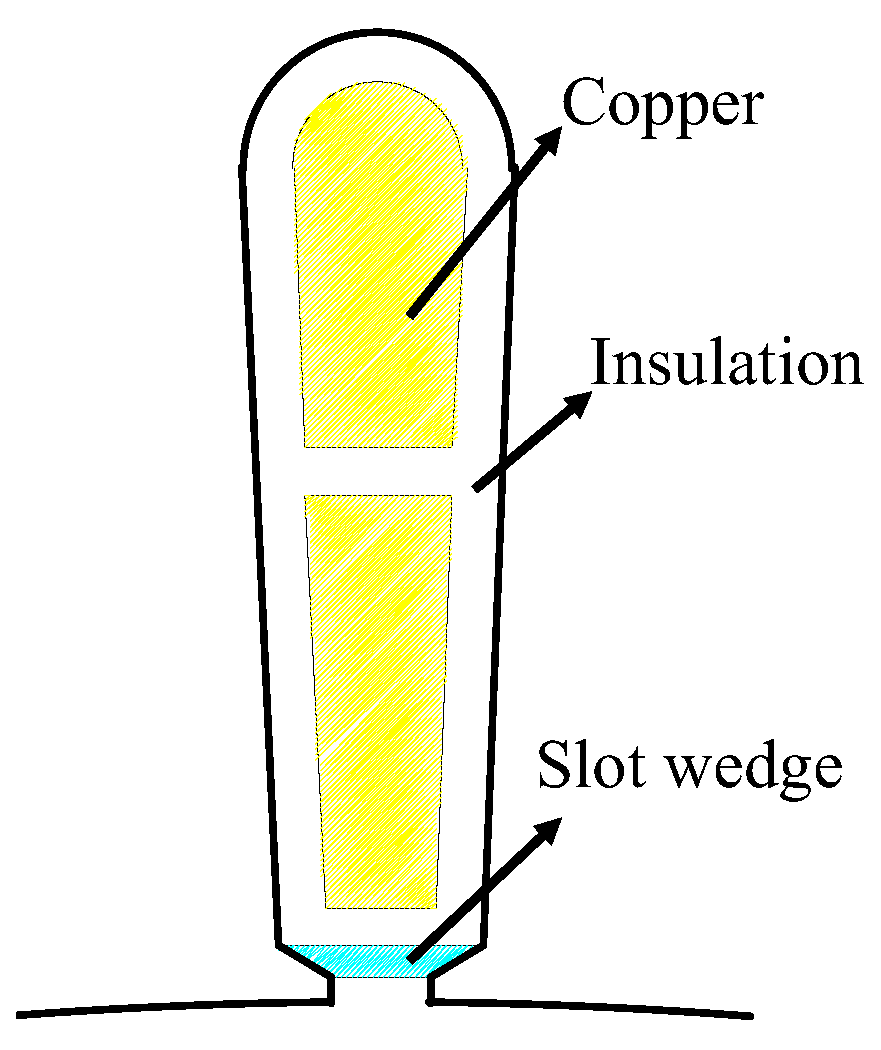
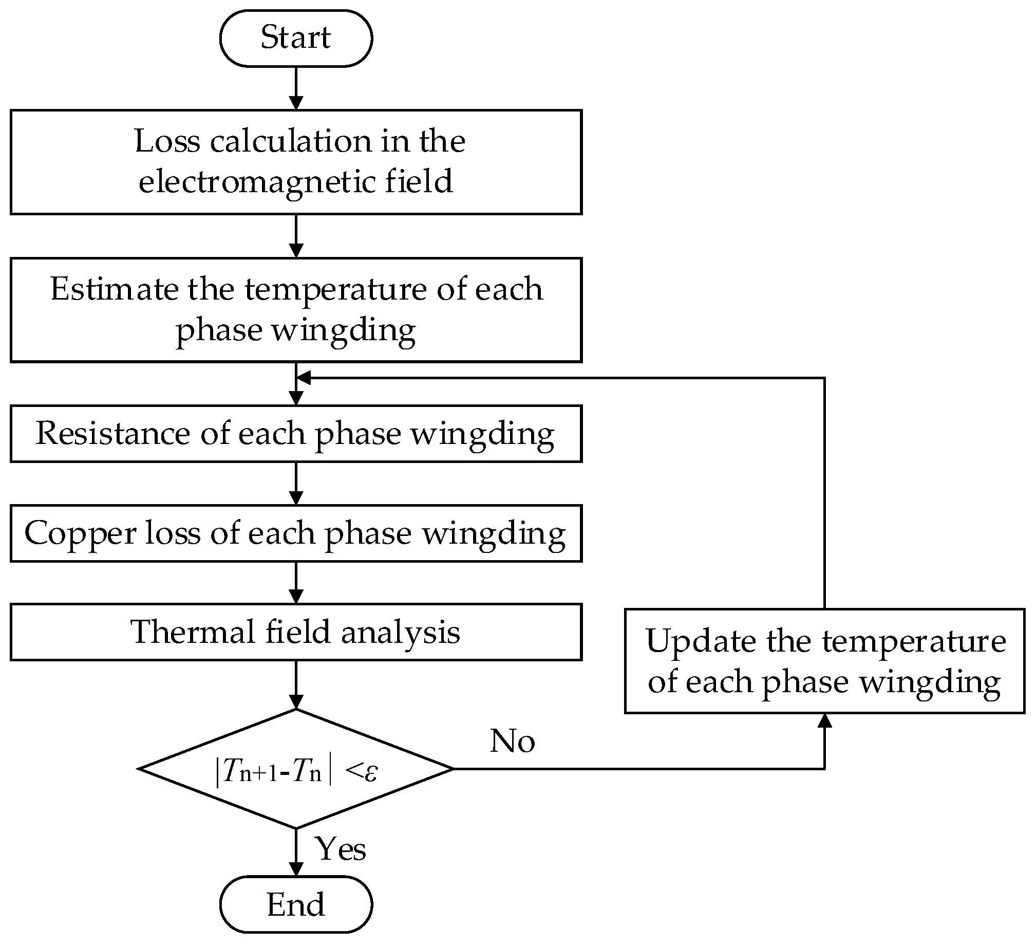
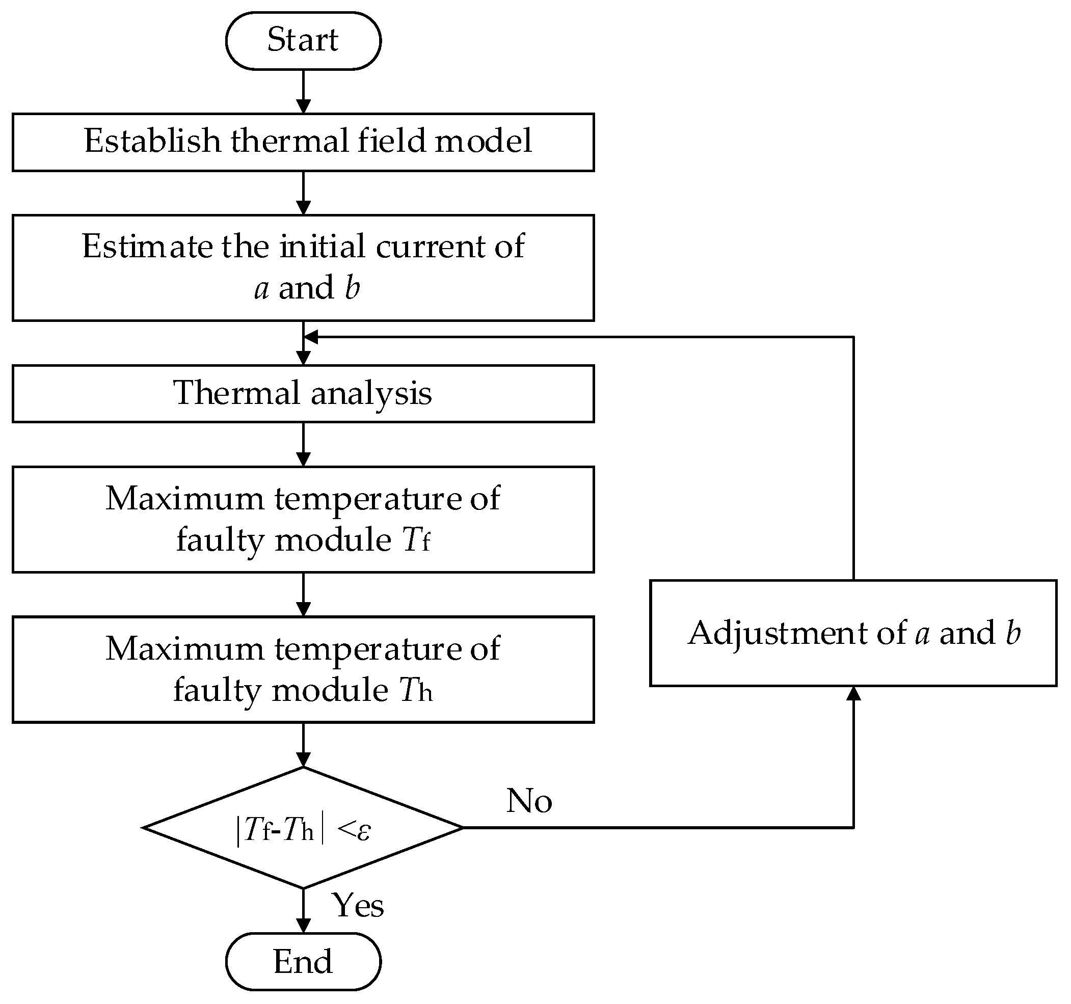
2.2. Thermal Field Model

3. Thermal Analysis
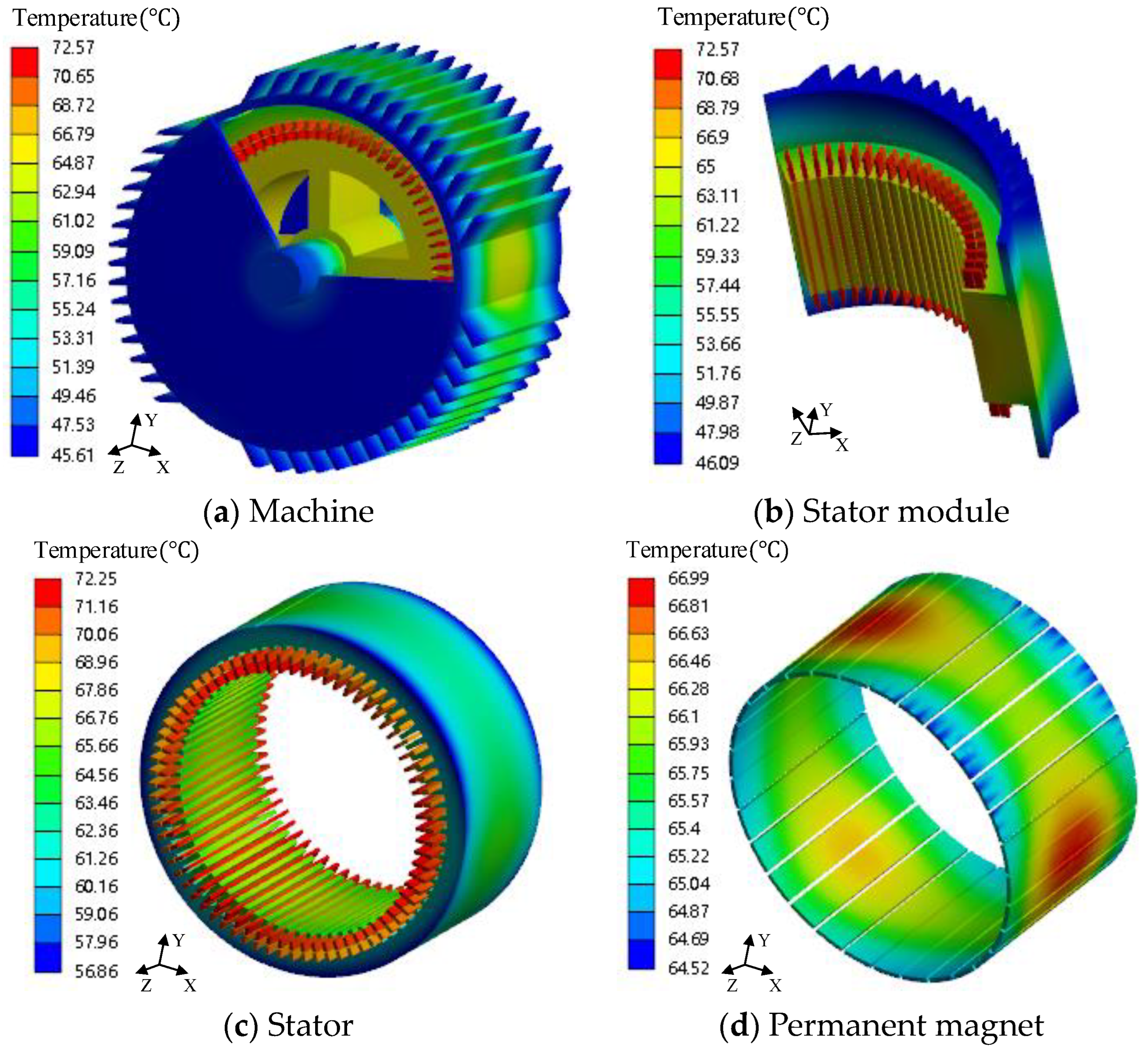
3.1. Thermal Analysis under the Rated Condition
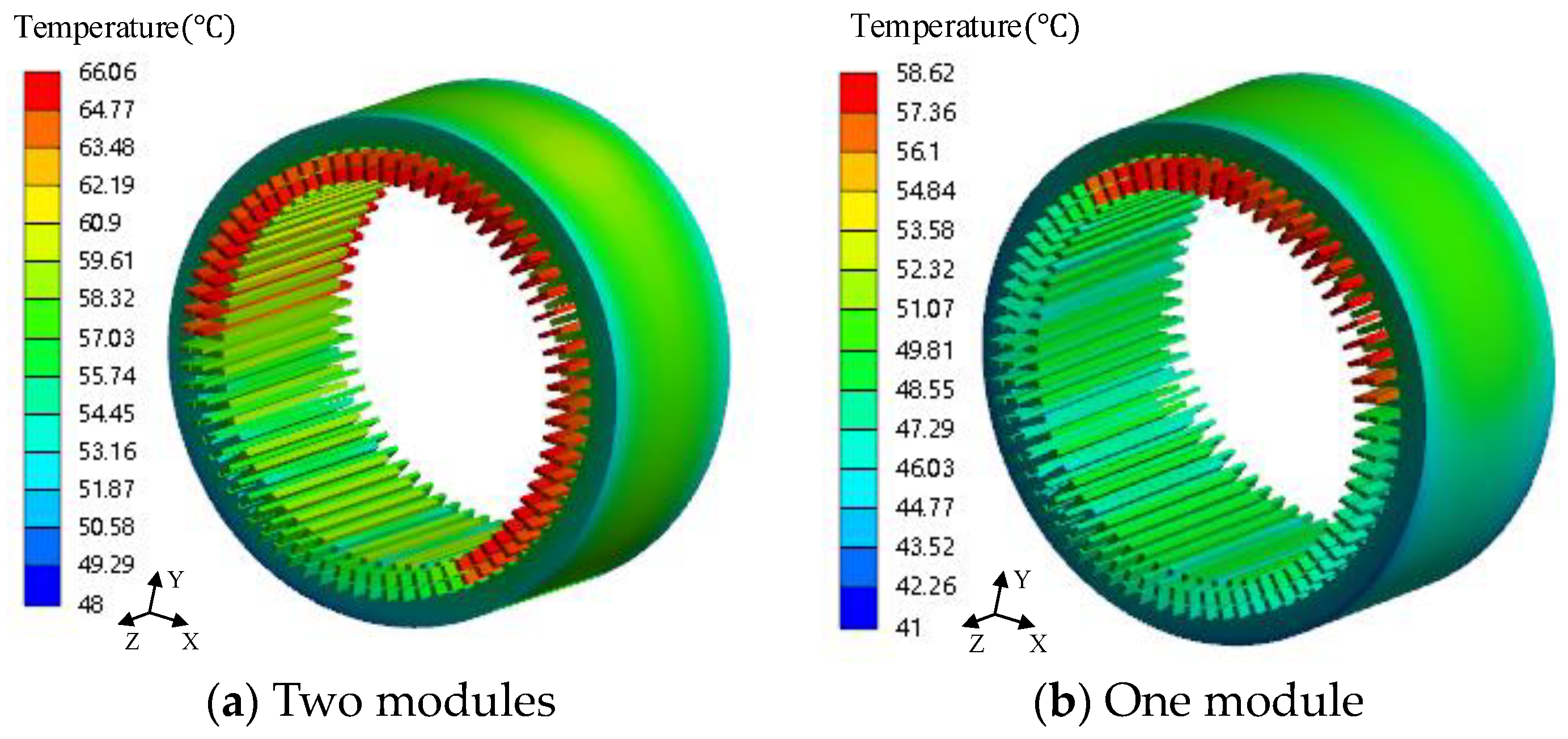
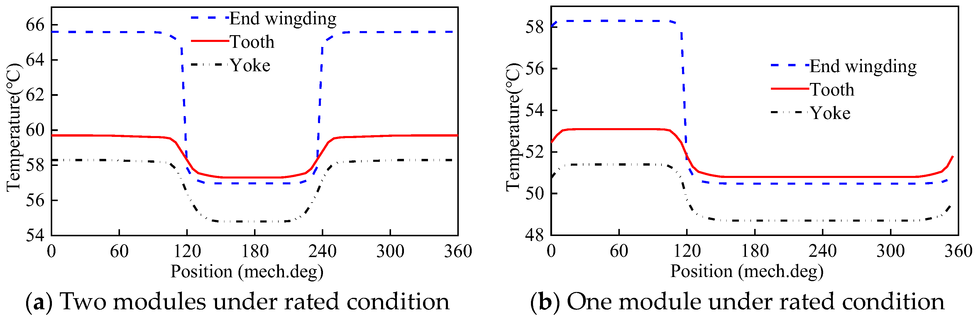
3.2. Thermal Analysis of Two Modules and One Module under the Rated Condition
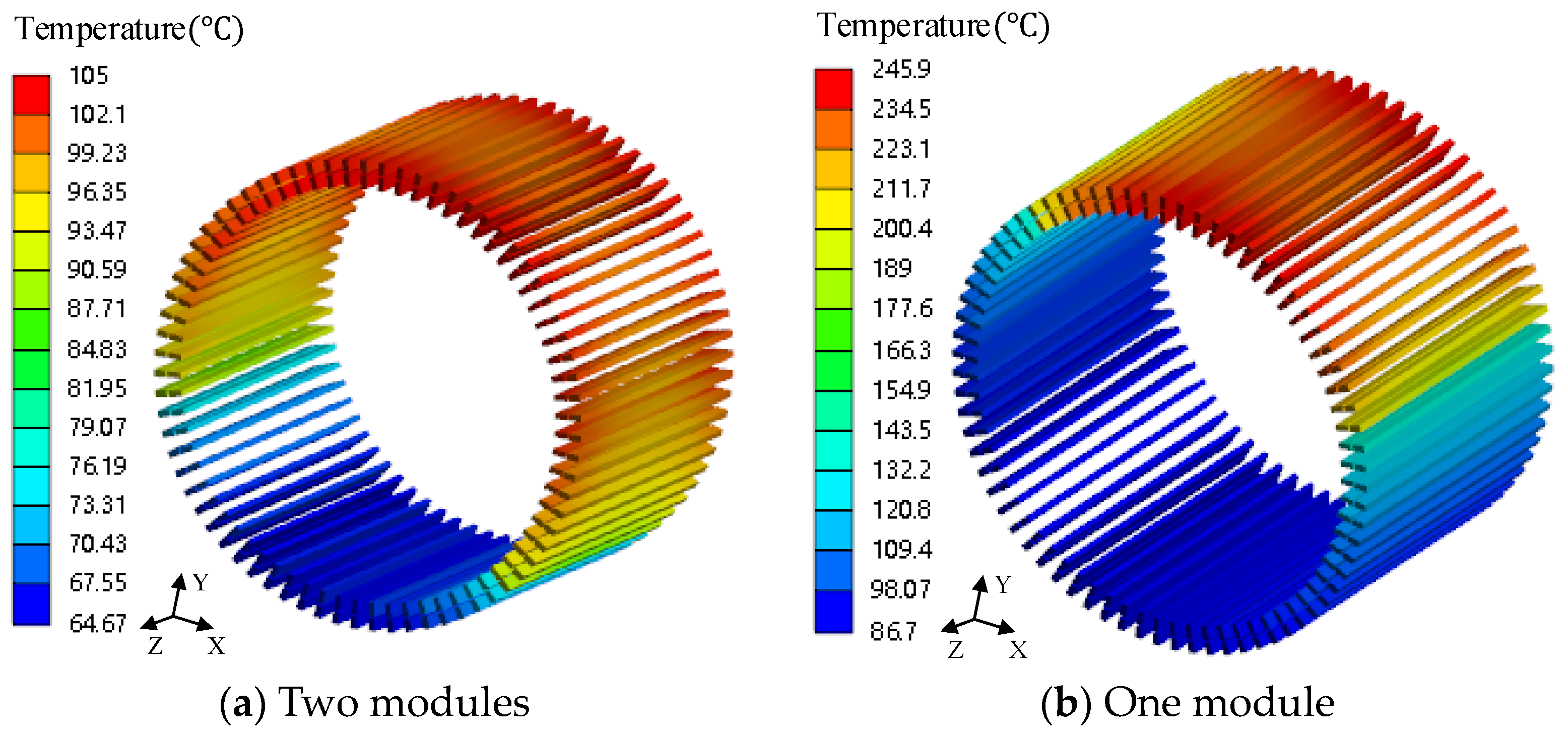
3.3. Thermal Analysis of Two Modules and One Module under the Fault-Tolerance Condition
3.4. Thermal Analysis under One-Phase Open-Circuit Conditions
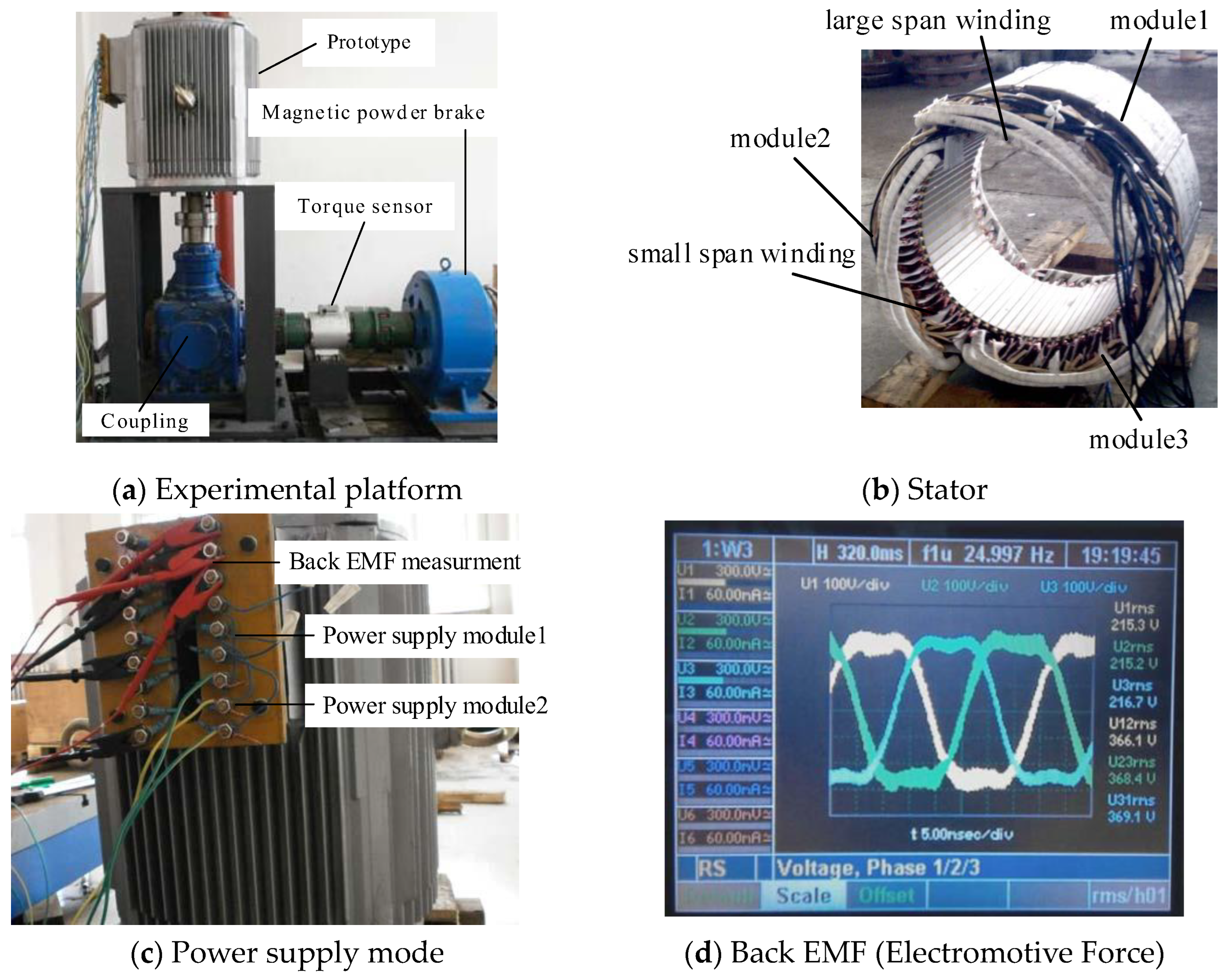
4. Experimental Results
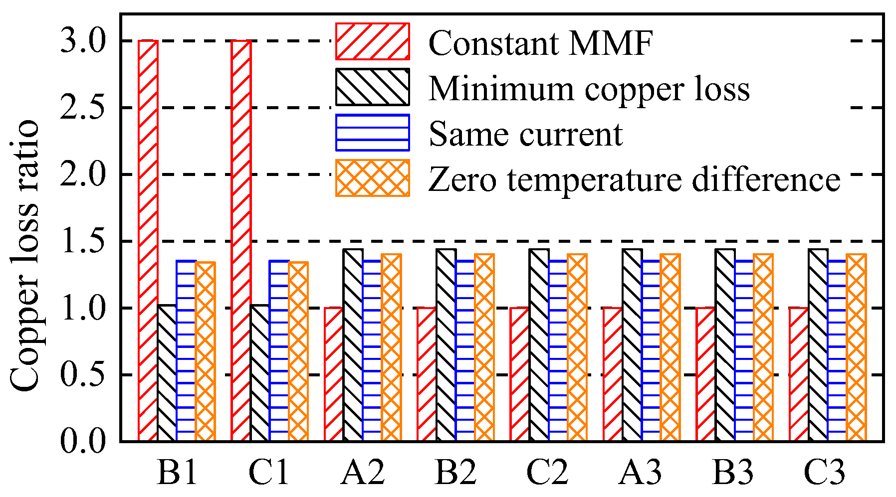
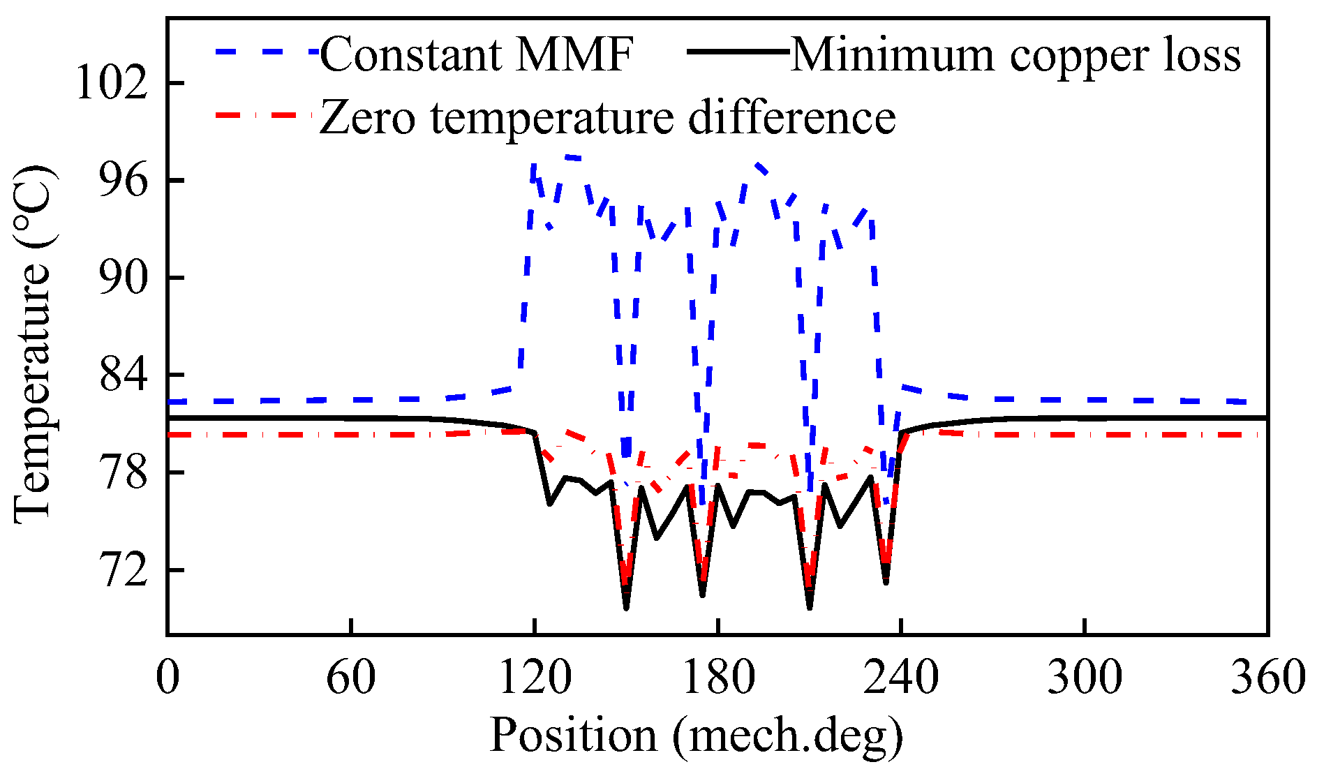
5. Discussion
6. Conclusions
Author Contributions
Funding
Data Availability Statement
Conflicts of Interest
References
- Jiang, X.; Huang, W.; Cao, R.; Hao, Z.; Jiang, W. Electric Drive System of Dual-Winding Fault-Tolerant Permanent-Magnet Motor for Aerospace Applications. IEEE Trans. Ind. Electron. 2015, 62, 7322–7330. [Google Scholar] [CrossRef]
- Wang, Y.; Hao, W. General Topology Derivation Methods and Control Strategies of Field Winding-Based Flux Adjustable PM Machines for Generator System in More Electric Aircraft. IEEE Trans. Transport. Electrific. 2020, 6, 1478–1496. [Google Scholar] [CrossRef]
- Wu, L.; Zhu, J.; Fang, Y. A Novel Doubly-Fed Flux-Switching Permanent Magnet Machine with Armature Windings Wound on Both Stator Poles and Rotor Teeth. IEEE Trans. Ind. Electron. 2020, 67, 10223–10232. [Google Scholar] [CrossRef]
- Sui, Y.; Yin, Z.; Cheng, L.; Zheng, P.; Tang, D. Multiphase Modular Fault-Tolerant Permanent-Magnet Machine with Hybrid Single/Double-Layer Fractional-Slot Concentrated Winding. IEEE Trans. Magn. 2019, 55, 7500506. [Google Scholar] [CrossRef]
- Zhou, H.; Xu, J.; Chen, C.; Tian, X.; Liu, G. Disturbance-Observer-Based Direct Torque Control of Five-Phase Permanent Magnet Motor Under Open-Circuit and Short-Circuit Faults. IEEE Trans. Ind. Electron. 2021, 68, 11907–11917. [Google Scholar] [CrossRef]
- Guo, H.; Guo, S.; Xu, J.; Tian, X. Power Switch Open-Circuit Fault Diagnosis of Six-Phase Fault Tolerant Permanent Magnet Synchronous Motor System under Normal and Fault-Tolerant Operation Conditions Using the Average Current Park’s Vector Approach. IEEE Trans. Power Electron. 2021, 36, 2641–2660. [Google Scholar] [CrossRef]
- Tang, H.; Li, W.; Li, J.; Gao, H.; Wu, Z.; Shen, X. Calculation and Analysis of the Electromagnetic Field and Temperature Field of the PMSM Based on Fault-Tolerant Control of Four-Leg Inverters. IEEE Trans. Energy Convers. 2020, 35, 2141–2151. [Google Scholar] [CrossRef]
- Wang, W.; Zhang, J.; Cheng, M. Common Model Predictive Control for Permanent-Magnet Synchronous Machine Drives Considering Single-Phase Open-Circuit Fault. IEEE Trans. Power Electron. 2017, 32, 5862–5872. [Google Scholar] [CrossRef]
- Zhang, B.; Gan, B.; Li, Q. Analysis of a Fault-Tolerant Module-Combined Stator Permanent Magnet Synchronous Machine. IEEE Access 2020, 8, 70438–70452. [Google Scholar] [CrossRef]
- Gan, B.; Zhang, B.; Li, Q.; Feng, G.; Li, G. Research on Operation of Low-Speed and High-Torque Module Combined Stator Permanent Magnetic Fault-Tolerant Motor with Unequal Span Winding. IEEE Access 2020, 8, 166824–166838. [Google Scholar] [CrossRef]
- Mo, L.; Zhang, T.; Lu, Q. Thermal Analysis of a Flux-Switching Permanent-Magnet Double-Rotor Machine With a 3-D Thermal Network Model. IEEE Trans. Appl. Supercond. 2019, 29, 0600905. [Google Scholar] [CrossRef]
- Zhao, W.; Cao, D.; Ji, J.; Huang, L.; Liu, T. A Generalized Mesh-Based Thermal Network Model for SPM Machines Combining Coupled Winding Solution. IEEE Trans. Ind. Electron. 2021, 68, 116–127. [Google Scholar] [CrossRef]
- Tong, W.; Sun, R.; Li, S.; Tang, R. Loss and Thermal Analysis for High-Speed Amorphous Metal PMSMs Using 3-D Electromagnetic-thermal Bi-Directional Coupling. IEEE Trans. Energy Convers. 2021, 36, 2839–2849. [Google Scholar] [CrossRef]
- Qi, J.; Hua, W.; Zhang, H. Thermal Analysis of Modular-Spoke-Type Permanent-Magnet Machines Based on Thermal Network and FEA Method. IEEE Trans. Magn. 2019, 55, 8104105. [Google Scholar] [CrossRef]
- Taras, P.; Li, G.; Zhu, Z.; Foster, M.; Stone, D. Combined Multiphysics Model of Switched Flux PM Machines under Fault Operations. IEEE Trans. Ind. Electron. 2019, 66, 6737–6745. [Google Scholar] [CrossRef]
- Tang, H.; Di, J.; Wu, Z.; Li, W. Temperature Analysis for the Asymmetric Six-Phase Permanent Magnet Synchronous Motor in Healthy and Fault-Tolerant Modes. IEEE Trans. Ind. Electron. 2023, 70, 6482–6493. [Google Scholar] [CrossRef]
- Shi, Y.; Wang, J.; Wang, B. Transient 3-D Lumped Parameter and 3-D FE Thermal Models of a PMASynRM under Fault Conditions with Asymmetric Temperature Distribution. IEEE Trans. Ind. Electron. 2021, 68, 4623–4633. [Google Scholar] [CrossRef]


| Material | X | Y | Z |
|---|---|---|---|
| Stator core (DW470) | 39 | 39 | 4.43 |
| Rotor core (DW470) | 39 | 39 | 4.43 |
| Winding (Copper) | 385 | 385 | 385 |
| Equivalent insulation | 0.27 | 0.27 | 0.27 |
| PM (N38UH) | 9 | 9 | 9 |
| Slot wedge | 0.2 | 0.2 | 0.2 |
| Shaft (Steel) | 45 | 45 | 45 |
| Parameter | Values and Unit |
|---|---|
| Rated power | 12 kW |
| Rated voltage | 380 V |
| Frequency | 25 Hz |
| Number of poles | 30 |
| Rated current (IN) | 20 A |
| Rated torque (TN) | 1146 Nm |
| Number of stator slots | 72 |
| Stator external diameter | 520 mm |
| Stator inner diameter | 390 mm |
| Core length | 220 mm |
| Air gap length | 0.8 mm |
| Number of rotor slots | 72 |
| No-load back EMF | 212 V |
| Number of modules | 3 |
| Small span | 2 |
| Large span | 22 |
| Efficiency | 90.5% |
| Power factor | 0.98 |
| Control Strategy | a | b | Loss | Temperature (°C) |
|---|---|---|---|---|
| Rated | 1 | 1 | 9I2 R | 72.3 |
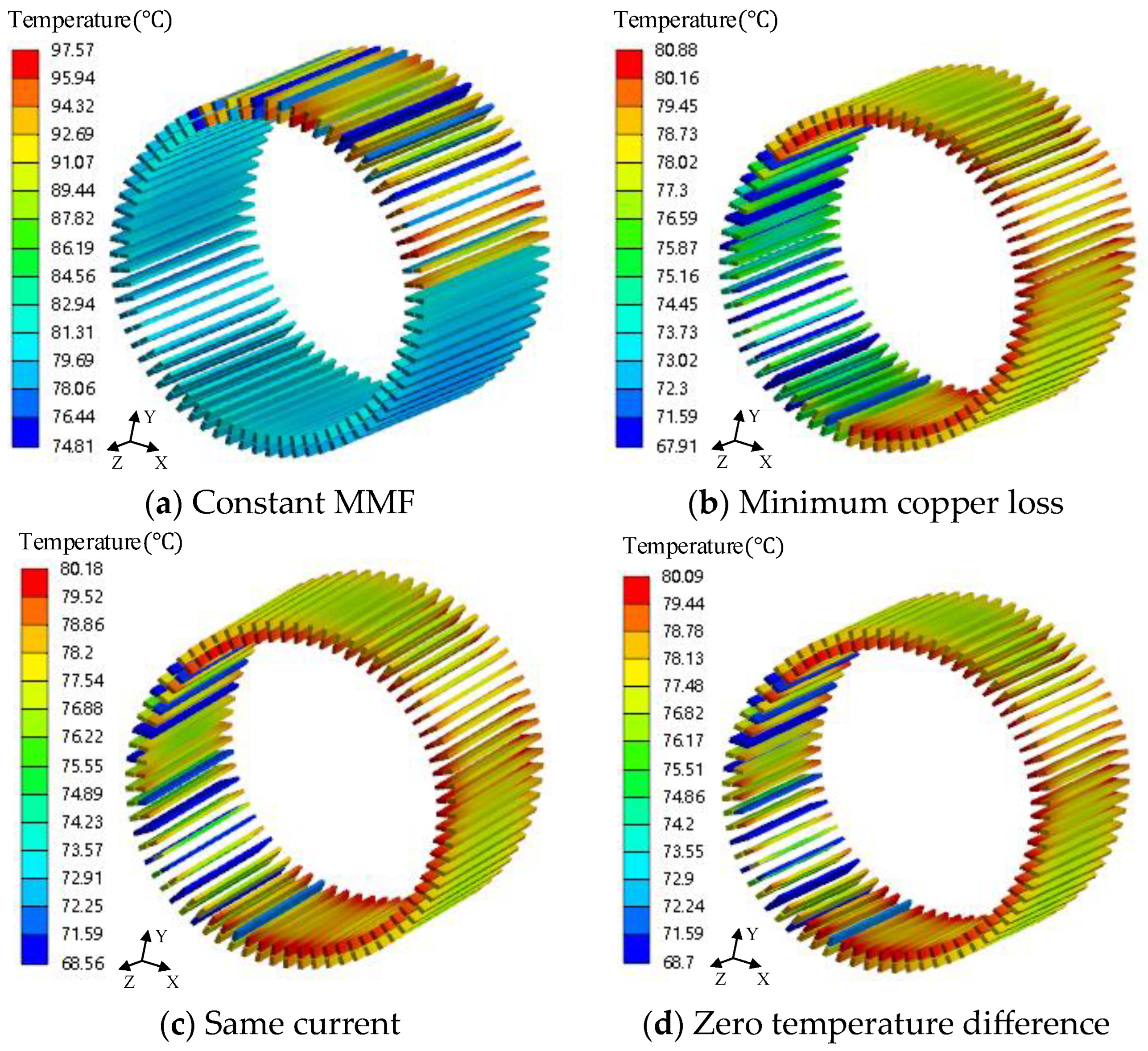
| Constant MMF | 1 | 1.732 | 12I2 R | 97.6 |
| Minimum copper loss | 1.2 | 1.04 | 10.8I2 R | 80.9 |
| Same current | 1.164 | 1.164 | 10.84I2 R | 80.2 |
| Zero temperature difference | 1.159 | 1.181 | 10.85I2 R | 80.1 |
| Operating Conditions | Calculated (°C) | Measured (°C) |
|---|---|---|
| One module under rated condition | 58.6 | 63.8 |
| Two modules under rated condition | 66.1 | 72.6 |
| Three modules under rated condition | 72.2 | 79.6 |
| One module rated under fault-tolerance condition | 150 | 165.2 |
| Two modules rated under fault-tolerance condition | 105 | 114.6 |
Disclaimer/Publisher’s Note: The statements, opinions and data contained in all publications are solely those of the individual author(s) and contributor(s) and not of MDPI and/or the editor(s). MDPI and/or the editor(s) disclaim responsibility for any injury to people or property resulting from any ideas, methods, instructions or products referred to in the content. |
© 2023 by the authors. Licensee MDPI, Basel, Switzerland. This article is an open access article distributed under the terms and conditions of the Creative Commons Attribution (CC BY) license (https://creativecommons.org/licenses/by/4.0/).
Share and Cite
Liu, Y.; Zhang, B.; Zong, M.; Feng, G. Thermal Analysis of a Modular Permanent Magnet Machine under Open-Circuit Fault with Asymmetric Temperature Distribution. Electronics 2023, 12, 1623. https://doi.org/10.3390/electronics12071623
Liu Y, Zhang B, Zong M, Feng G. Thermal Analysis of a Modular Permanent Magnet Machine under Open-Circuit Fault with Asymmetric Temperature Distribution. Electronics. 2023; 12(7):1623. https://doi.org/10.3390/electronics12071623
Chicago/Turabian StyleLiu, Yunfei, Bingyi Zhang, Ming Zong, and Guihong Feng. 2023. "Thermal Analysis of a Modular Permanent Magnet Machine under Open-Circuit Fault with Asymmetric Temperature Distribution" Electronics 12, no. 7: 1623. https://doi.org/10.3390/electronics12071623