

Model Predictive Control Based Energy Management Strategy of Series Hybrid Electric Vehicles Considering Driving Pattern Recognition
Abstract
:1. Introduction
1.1. Literature Review
- As a complex power component, the performance of the engine in dynamic response is often unsatisfactory. In addition to the characteristics of preheating before stable operation, the battery output can be dominant when the vehicle is started. This is due to the fast response of the battery and the characteristics of the motor-low speed and large torque. Under this condition, the vehicle can start quickly and smoothly, the acceleration performance is significantly improved, the power output is stable, and the emission reduction of the vehicle is also significantly improved [3].
- The service life of the engine will be correspondingly increased because it can avoid the engine working in the inefficient area.
- During braking and downhill deceleration, the braking energy can be recovered and stored in the battery.
- The system description of vehicles is often complex and nonlinear, which has caused a huge obstacle to simulation modeling and control strategy design. How to describe the system reasonably, reasonable simplification, and mathematical processing are essential.
- The conditions encountered by the vehicle during the driving process are changeable and the speed of change is extremely fast, and the basis of energy management decision-making is difficult to accurately determine.
- The driving styles of drivers are different, and the terrain that vehicles encounter at every moment is also changeable [4,5]. Therefore, in future research, vehicles should be considered as a part of a larger system, and energy management should be allocated in combination with various information.
1.2. Motivation and Contribution
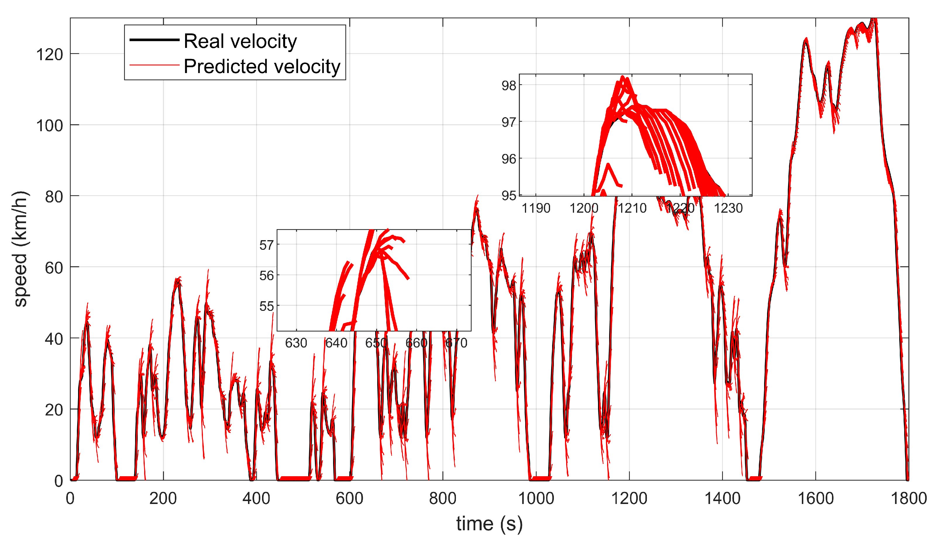
2. Driving Pattern Recognition and Speed Prediction
3. MPC-Based Energy Management Strategy
3.1. Demanded Power Calculation
3.2. System Model
3.3. Linearizing Predictive Model
3.4. Optimization Process
3.5. Interior Point Method
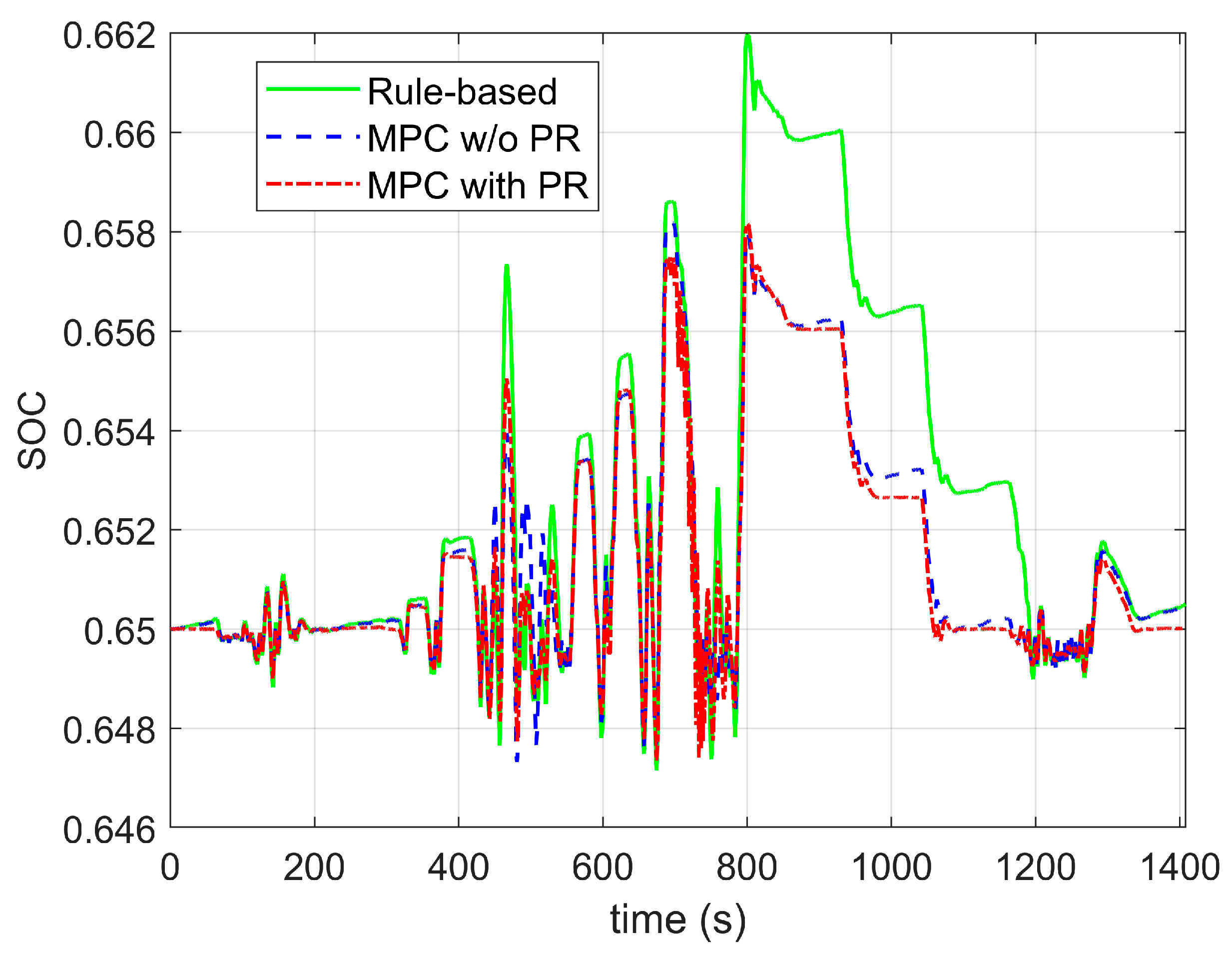
3.6. Simulation Results
4. Conclusions
Author Contributions
Funding
Data Availability Statement
Conflicts of Interest
Nomenclature
| HEV | hybrid electric vehicle |
| EMS | energy management strategy |
| EM | expectation maximization |
| SOC | state of charge |
| MPC | model predictive control |
| ECMS | equivalent consumption minimization strategy |
| DP | dynamic programming |
| PR | pattern recognition |
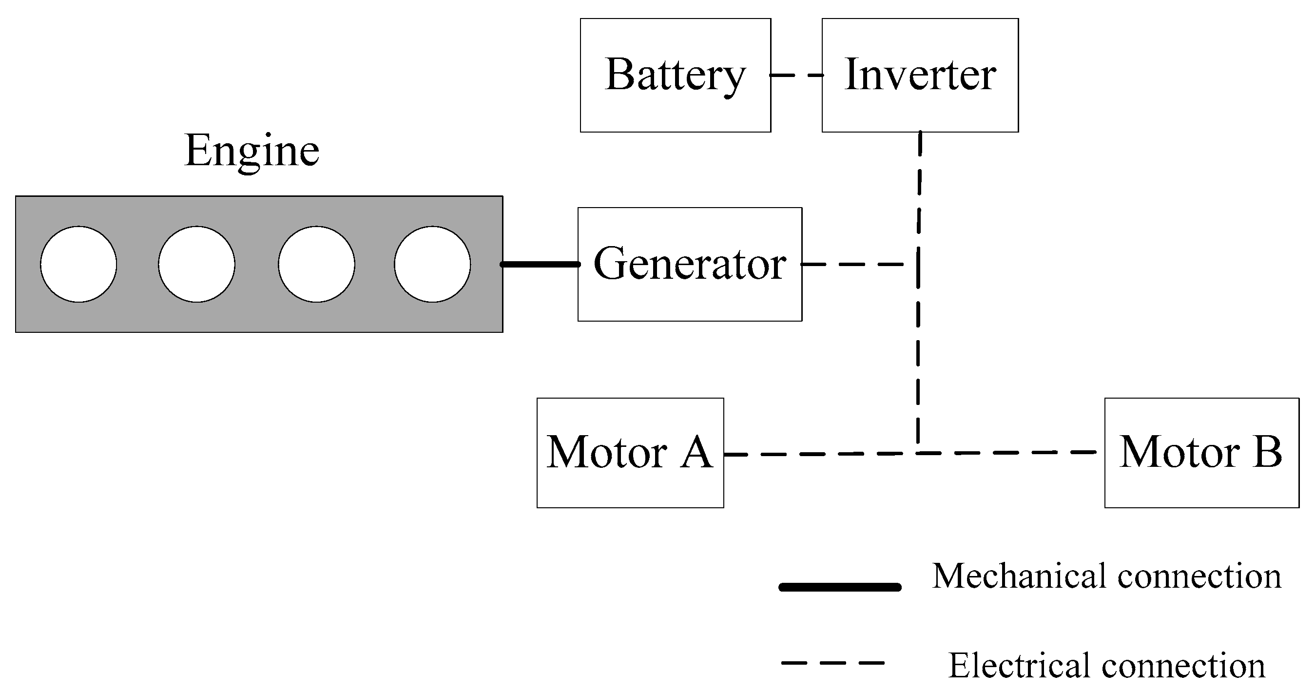
| EGS | engine generator set |
| DB | Davies-Bouldin index |
References
- Peng, J.; He, H.; Xiong, R. Rule based energy management strategy for a series-parallel plug-in hybrid electric bus optimized by dynamic programming. Appl. Energy 2017, 185, 1633–1643. [Google Scholar] [CrossRef]
- Ruan, S.; Ma, Y. Real-Time Energy Management Strategy Based on Driver-Action-Impact MPC for Series Hybrid Electric Vehicles. Complexity 2020, 2020, 8843168. [Google Scholar] [CrossRef]
- Sorrentino, M.R.G.; Arsie, I. Analysis of a rule-based control strategy for on-board energy management of series hybrid vehicles. Control. Eng. Pract. 2011, 19, 1433–1441. [Google Scholar] [CrossRef]
- Li, L.; Coskun, S.; Zhang, F.; Langari, R.; Xi, J. Energy management of hybrid electric vehicle using vehicle lateral dynamic in velocity prediction. IEEE Trans. Veh. Technol. 2019, 68, 3279–3293. [Google Scholar] [CrossRef]
- Liu, K.; Asher, Z.; Gong, X.; Huang, M.; Kolmanovsky, I. Vehicle Velocity Prediction and Energy Management Strategy Part 1: Deterministic and Stochastic Vehicle Velocity Prediction Using Machine Learning; 0148-7191; SAE Technical Paper: Warrendale, PA, USA, 2019. [Google Scholar]
- Frambach, T.; Liedtke, R.; Dechent, P.; Sauer, D.U.; Figgemeier, E. A Review on Aging-Aware System Simulation for Plug-In Hybrids. IEEE Trans. Transp. Electrif. 2022, 8, 1524–1540. [Google Scholar] [CrossRef]
- Biswas, A.; Emadi, A. Energy Management Systems for Electrified Powertrains: State-of-The-Art Review and Future Trends. IEEE Trans. Veh. Technol. 2019, 68, 6453–6467. [Google Scholar] [CrossRef]
- Huang, Y.; Wang, H.; Khajepour, A.; Li, B.; Hu, C. A review of power management strategies and component sizing methods for hybrid vehicles. Renew. Sustain. Energy Rev. 2018, 96, 132–144. [Google Scholar] [CrossRef]
- Silvas, E.; Hofman, T.; Murgovski, N.; Etman, L.F.P.; Steinbuch, M. Review of Optimization Strategies for System-Level Design in Hybrid Electric Vehicles. IEEE Trans. Veh. Technol. 2017, 66, 57–70. [Google Scholar] [CrossRef]
- Martinez, C.M.; Hu, X.; Cao, D.; Velenis, E.; Gao, B.; Wellers, M. Energy Management in Plug-in Hybrid Electric Vehicles: Recent Progress and a Connected Vehicles Perspective. IEEE Trans. Veh. Technol. 2017, 66, 4534–4549. [Google Scholar] [CrossRef] [Green Version]
- Pérez, L.V.; Bossio, G.R.; Moitre, D.; García, G.O. Optimization of power management in an hybrid electric vehicle using dynamic programming. Math. Comput. Simul. 2006, 73, 244–254. [Google Scholar] [CrossRef]
- Bertsekas, D.P. Dynamic Programming and Optimal Control, 3rd ed.; Athena Scientific: Belmont, MA, USA, 2011; Volume II. [Google Scholar]
- Bellman, R. Dynamic programming. Science 1966, 153, 34–37. [Google Scholar] [CrossRef]
- Serrao, S.O.a.G.R.L. ECMS as a realization of Pontryagin’s minimum principle for HEV control. In Proceedings of the 2009 American Control Conference, St. Louis, MO, USA, 10–12 June 2009; pp. 3964–3969. [Google Scholar]
- Musardo, C.; Rizzoni, G.; Guezennec, Y.; Staccia, B. A-ECMS: An Adaptive Algorithm for Hybrid Electric Vehicle Energy Management. In Proceedings of the 44th IEEE Conference on Decision and Control, Seville, Spain, 15 December 2005; pp. 1816–1823. [Google Scholar]
- Huang, Y.; Wang, H.; Khajepour, A.; He, H.; Ji, J. Model predictive control power management strategies for HEVs: A review. J. Power Sources 2017, 341, 91–106. [Google Scholar] [CrossRef]
- Capata, R. Urban and Extra-Urban Hybrid Vehicles: A Technological Review. Energies 2018, 11, 2924. [Google Scholar] [CrossRef] [Green Version]
- Meng, J.; Yue, M.; Diallo, D. Nonlinear extension of battery constrained predictive charging control with transmission of Jacobian matrix. Int. J. Electr. Power Energy Syst. 2023, 146, 108762. [Google Scholar] [CrossRef]
- Xiang, C.L.; Ding, F.; Wang, W.D.; He, W. Energy management of a dual-mode power-split hybrid electric vehicle based on velocity prediction and nonlinear model predictive control. Appl. Energy 2017, 189, 640–653. [Google Scholar] [CrossRef]
- Doff-Sotta, M.; Cannon, M.; Bacic, M. Predictive Energy Management for Hybrid Electric Aircraft Propulsion Systems. IEEE Trans. Control. Syst. Technol. 2022, 31, 602–614. [Google Scholar] [CrossRef]
- Guo, N.; Zhang, X.; Zou, Y.; Guo, L.; Du, G. Real-time predictive energy management of plug-in hybrid electric vehicles for coordination of fuel economy and battery degradation. Energy 2021, 214, 119070. [Google Scholar] [CrossRef]
- Wang, H.; Huang, Y.; Khajepour, A.; Song, Q. Model predictive control-based energy management strategy for a series hybrid electric tracked vehicle. Appl. Energy 2016, 182, 105–114. [Google Scholar] [CrossRef] [Green Version]
- Wang, W.; Guo, X.; Yang, C.; Zhang, Y.; Zhao, Y.; Huang, D.; Xiang, C. A multi-objective optimization energy management strategy for power split HEV based on velocity prediction. Energy 2021, 238, 121714. [Google Scholar] [CrossRef]
- Schmid, R.; Buerger, J.; Bajcinca, N. Energy Management Strategy for Plug-in-Hybrid Electric Vehicles Based on Predictive PMP. IEEE Trans. Control. Syst. Technol. 2021, 29, 2548–2560. [Google Scholar] [CrossRef]
- Ruan, S.; Ma, Y.; Yang, N.; Xiang, C.; Li, X. Real-time energy-saving control for HEVs in car-following scenario with a double explicit MPC approach. Energy 2022, 247, 123265. [Google Scholar] [CrossRef]
- Xiao, J.; Lu, J.; Li, X. Davies Bouldin Index based hierarchical initialization K-means. Intell. Data Anal. 2017, 21, 1327–1338. [Google Scholar] [CrossRef]
- Jain, S. Markov chain model and its application. Comput. Biomed. Res. 1986, 19, 374–378. [Google Scholar] [CrossRef]
- Mitschke, M.; Wallentowitz, H. Dynamik der Kraftfahrzeuge; Springer: Berlin/Heidelberg, Germany, 1972; Volume 4. [Google Scholar]
- Boyd, S.; Boyd, S.P.; Vandenberghe, L. Convex Optimization; Cambridge University Press: Cambridge, UK, 2004. [Google Scholar]


| Time Error | 1st | 2nd | 3rd | 4th | 5th |
|---|---|---|---|---|---|
| Max error (km/h) | 0.3572 | 0.5236 | 0.7692 | 1.0751 | 1.7846 |
| Ave error (km/h) | 0.2918 | 0.3982 | 0.6732 | 0.8736 | 1.2358 |
| Time Error | 1st | 2nd | 3rd | 4th | 5th |
|---|---|---|---|---|---|
| Max error (km/h) | 0.6723 | 0.9762 | 1.3674 | 2.3268 | 3.1469 |
| Ave error (km/h) | 0.4174 | 0.7214 | 0.9826 | 1.6746 | 2.3478 |
| Condition Predict Method | RMSE |
|---|---|
| Prediction error with recognition | 1.1834 |
| Prediction error without recognition | 2.0762 |
| Parameter | Value | Unit |
|---|---|---|
| Vehicle mass m | 8000 | kg |
| Radius of wheels rw | 0.38 | m |
| Windward area A | 3.24 | m2 |
| Air resistance coefficient CD | 0.38 | - |
| rolling resistance coefficient f | 0.015 | - |
| Capacity of battery pack Cmax | 20 | Ah |
| Voltage of battery pack Voc | 360 | V |
| Rated power of the engine | 120 | kW |
| Rated power of the generator | 120 | kW |
| Rated power of the motor | 160 | kW |
Disclaimer/Publisher’s Note: The statements, opinions and data contained in all publications are solely those of the individual author(s) and contributor(s) and not of MDPI and/or the editor(s). MDPI and/or the editor(s) disclaim responsibility for any injury to people or property resulting from any ideas, methods, instructions or products referred to in the content. |
© 2023 by the authors. Licensee MDPI, Basel, Switzerland. This article is an open access article distributed under the terms and conditions of the Creative Commons Attribution (CC BY) license (https://creativecommons.org/licenses/by/4.0/).
Share and Cite
Hao, J.; Ruan, S.; Wang, W. Model Predictive Control Based Energy Management Strategy of Series Hybrid Electric Vehicles Considering Driving Pattern Recognition. Electronics 2023, 12, 1418. https://doi.org/10.3390/electronics12061418
Hao J, Ruan S, Wang W. Model Predictive Control Based Energy Management Strategy of Series Hybrid Electric Vehicles Considering Driving Pattern Recognition. Electronics. 2023; 12(6):1418. https://doi.org/10.3390/electronics12061418
Chicago/Turabian StyleHao, Jinna, Shumin Ruan, and Wei Wang. 2023. "Model Predictive Control Based Energy Management Strategy of Series Hybrid Electric Vehicles Considering Driving Pattern Recognition" Electronics 12, no. 6: 1418. https://doi.org/10.3390/electronics12061418