
Automated Guided Vehicle (AGV) Driving System Using Vision Sensor and Color Code

Abstract
:1. Introduction
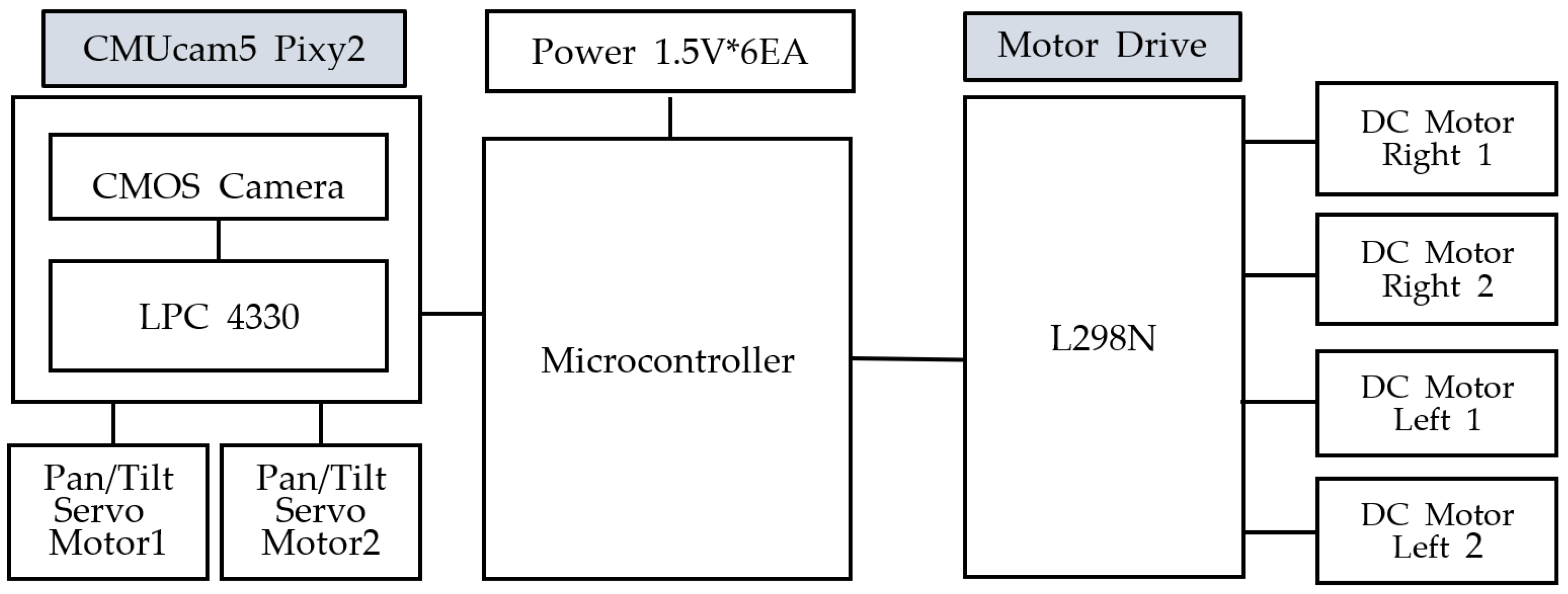
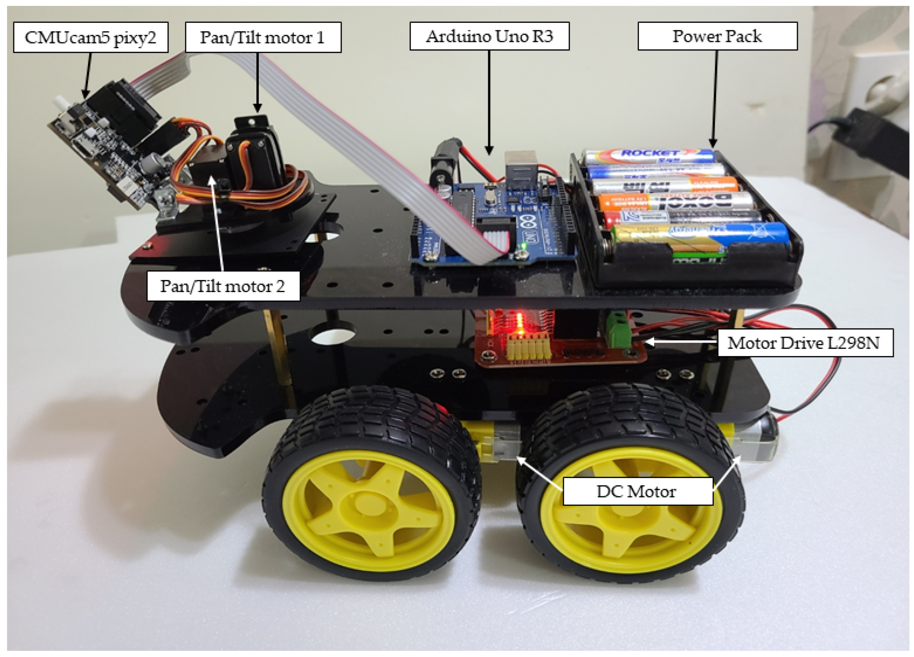
2. AGVA-Robot Driving System
2.1. Materials
2.1.1. CMUcam5 Pixy2
2.1.2. Arduino Uno R3
2.1.3. L298N Motor Driver
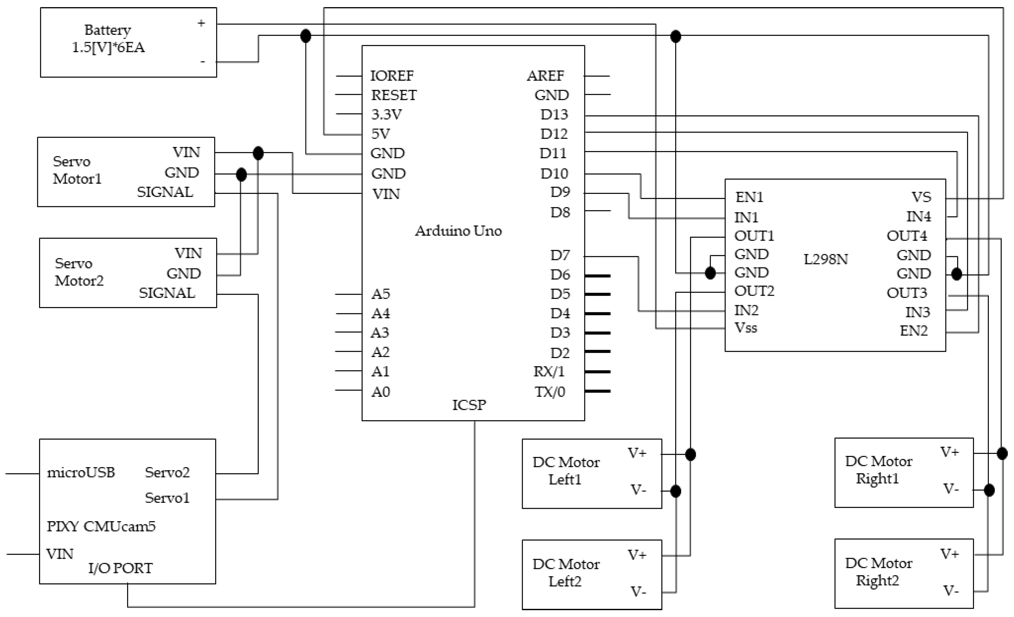
2.2. Circuit Design
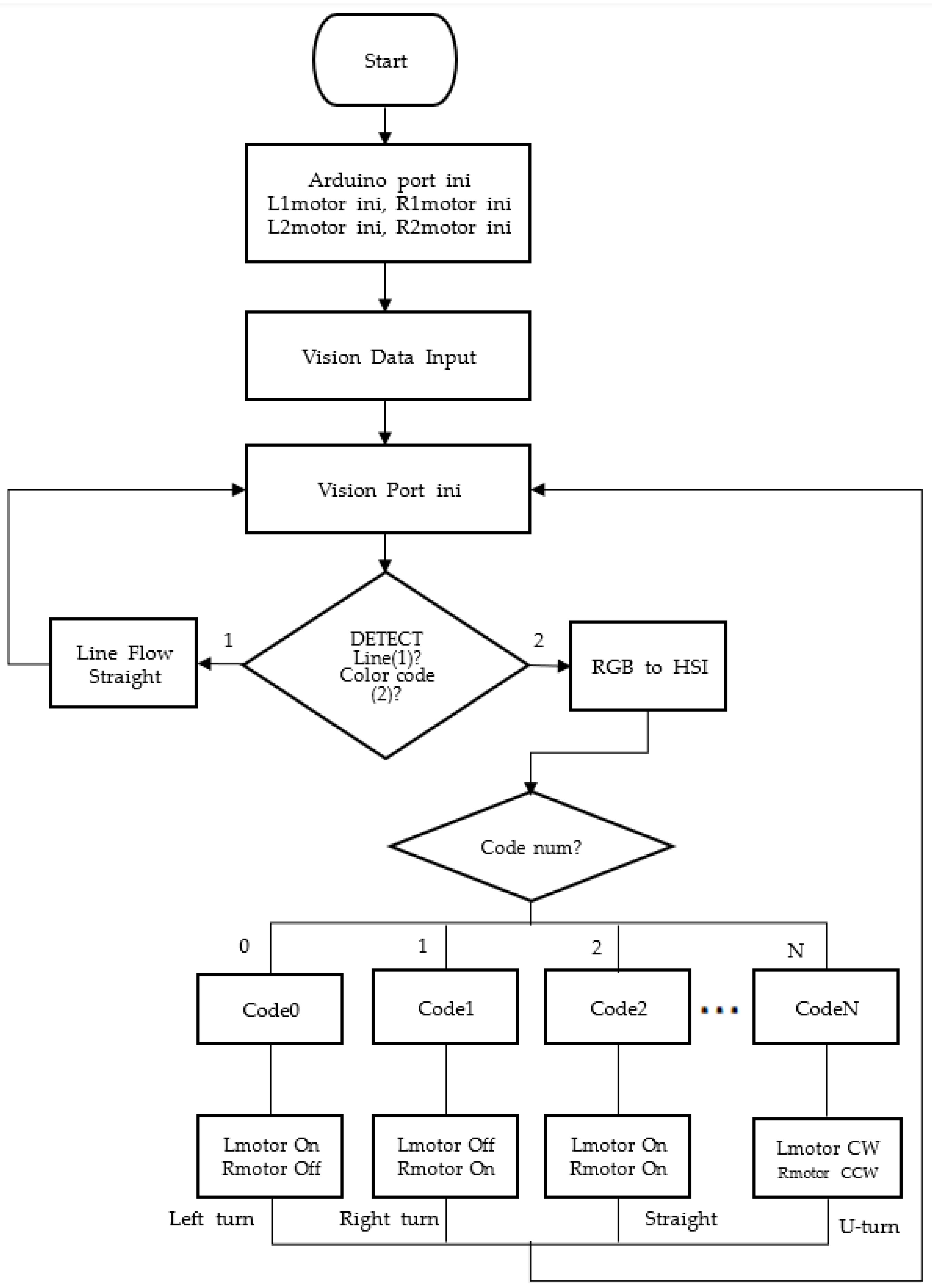
2.3. Operating Flowchart
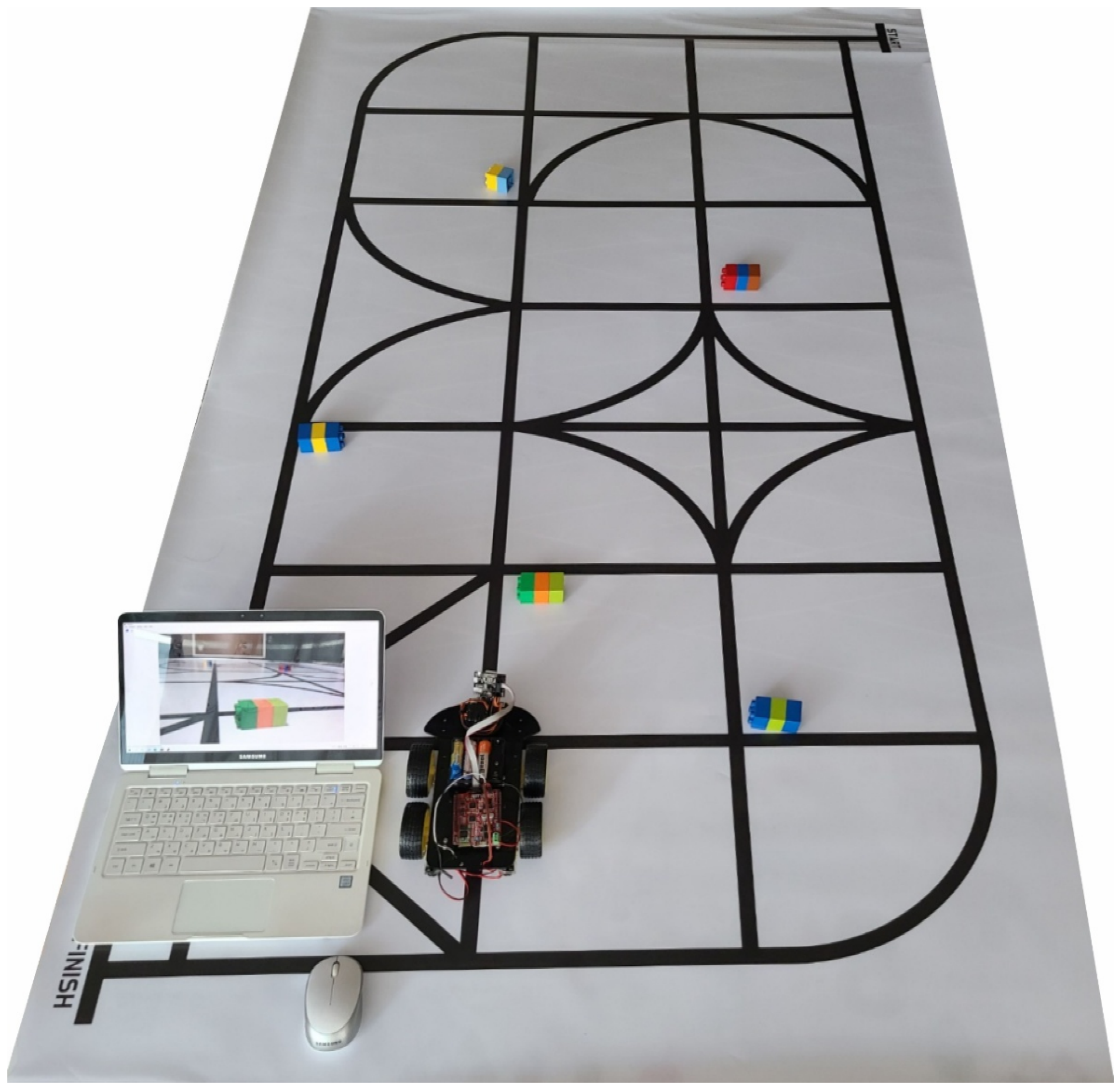
2.4. Experimental Environment
3. Color Model
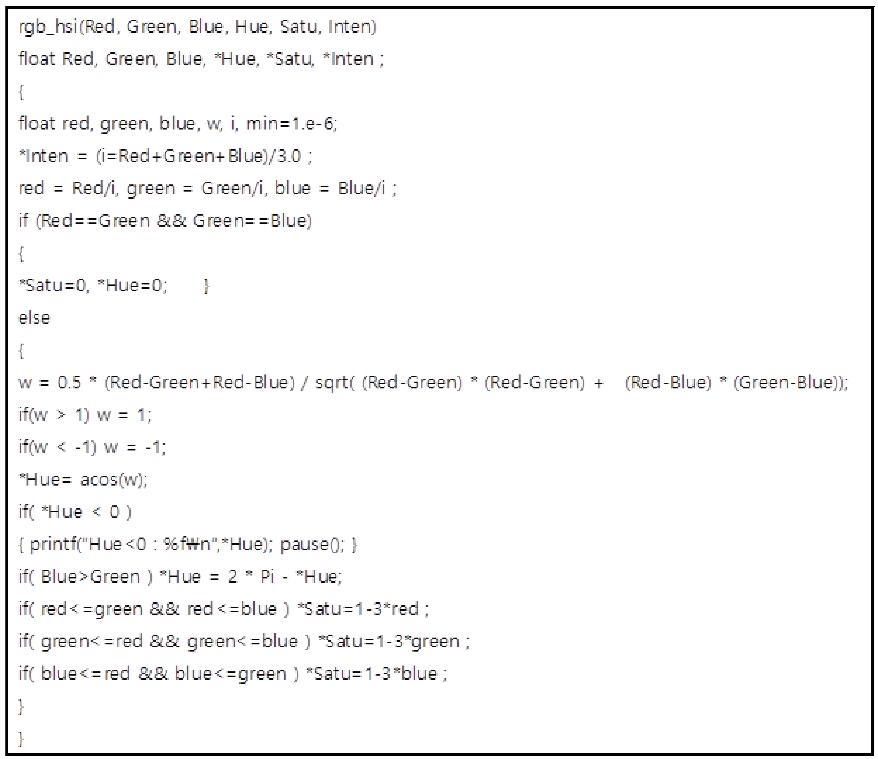
3.1. RGB to HSI
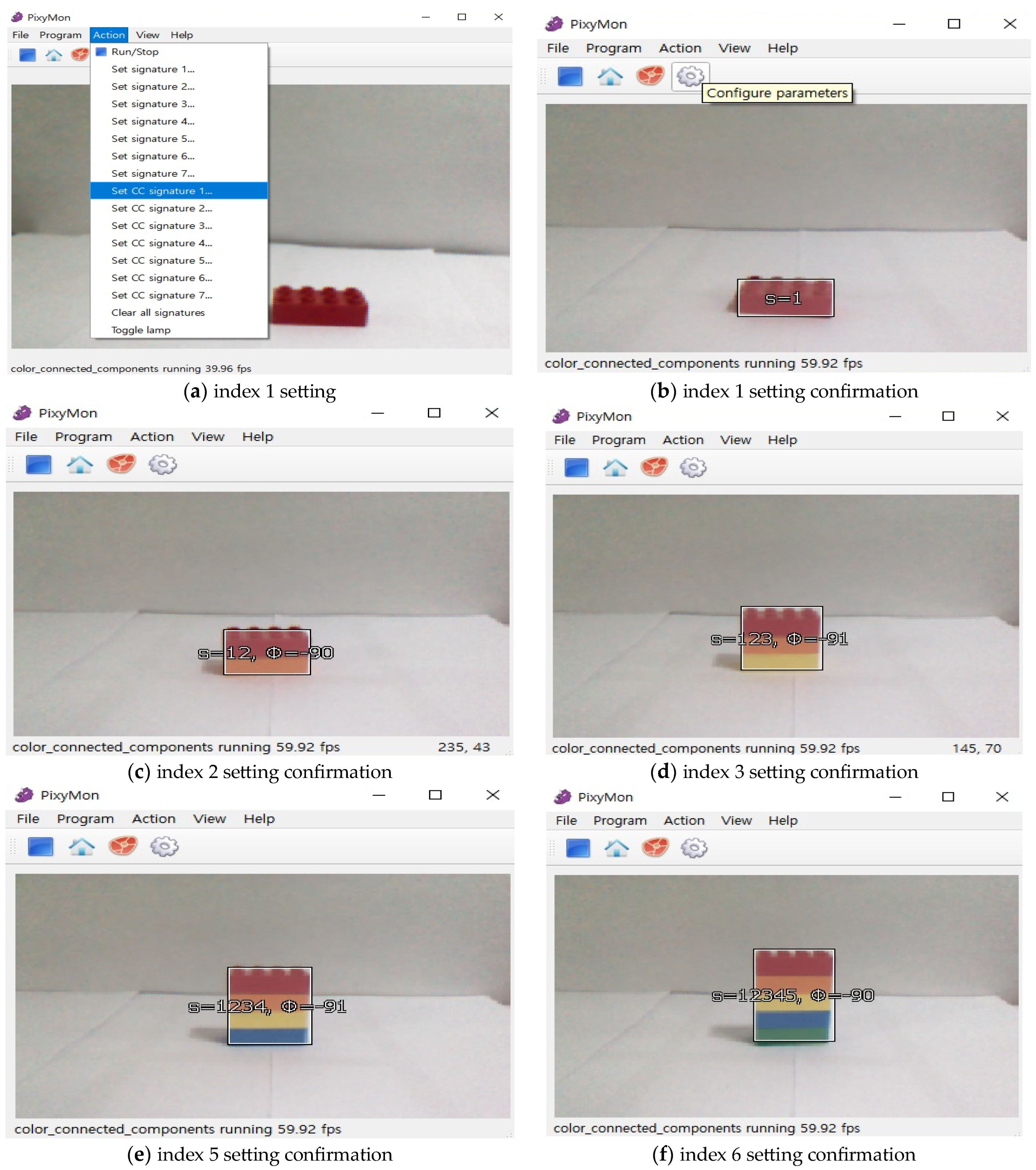
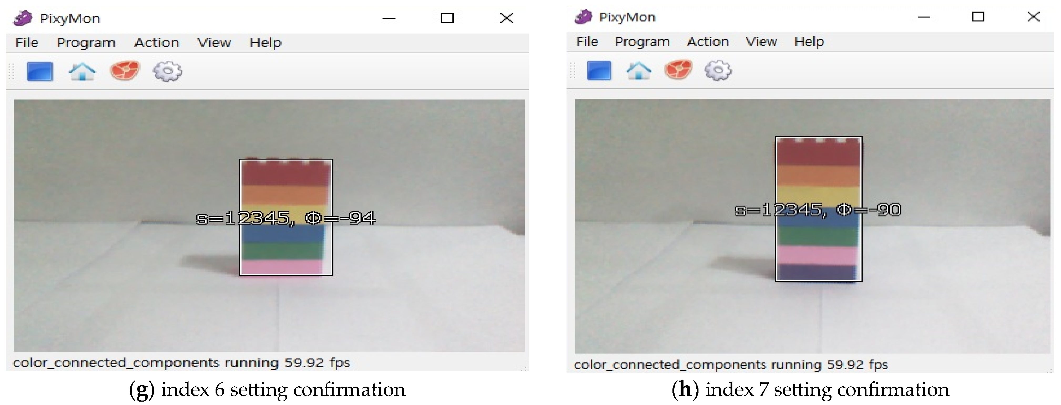
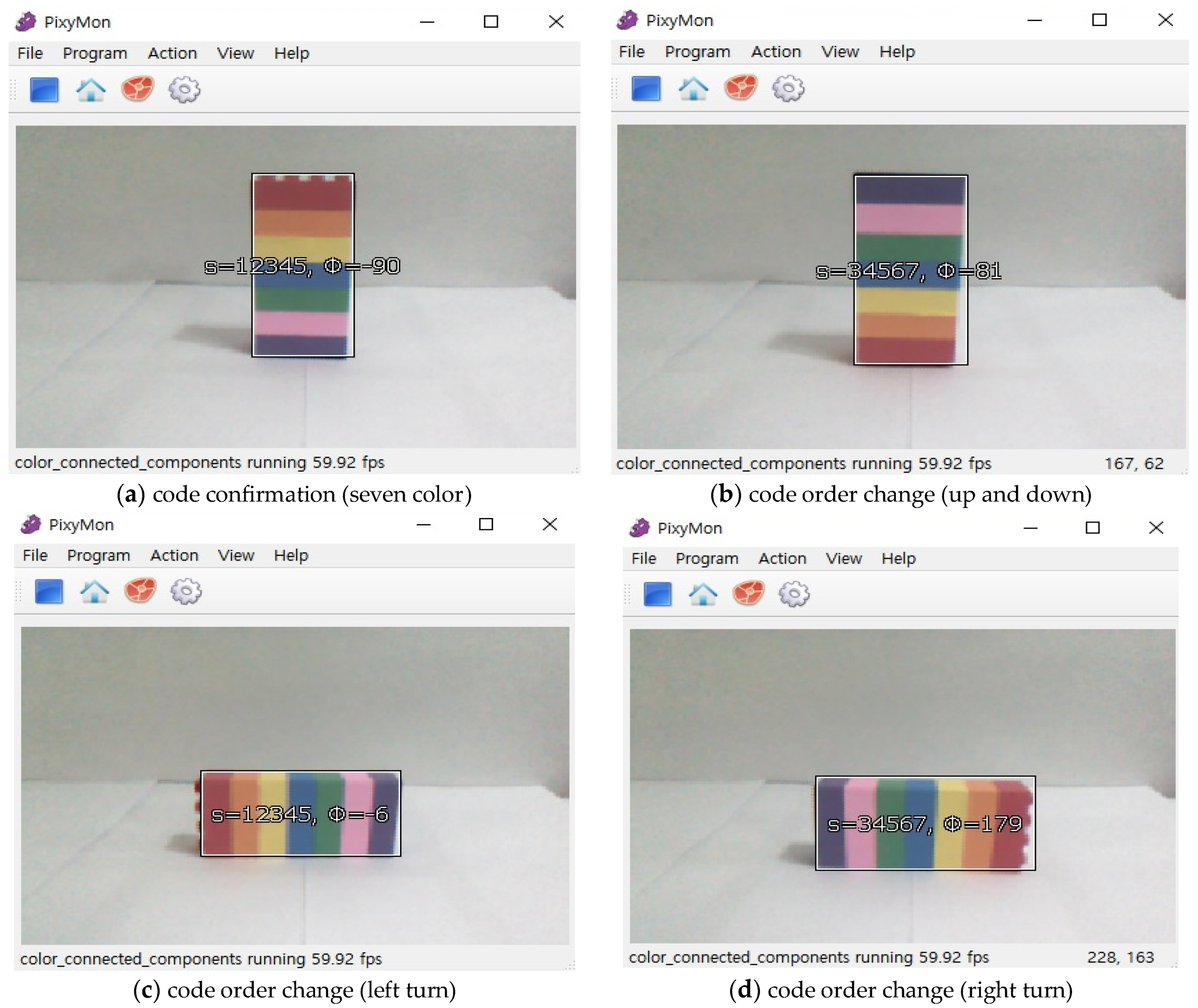
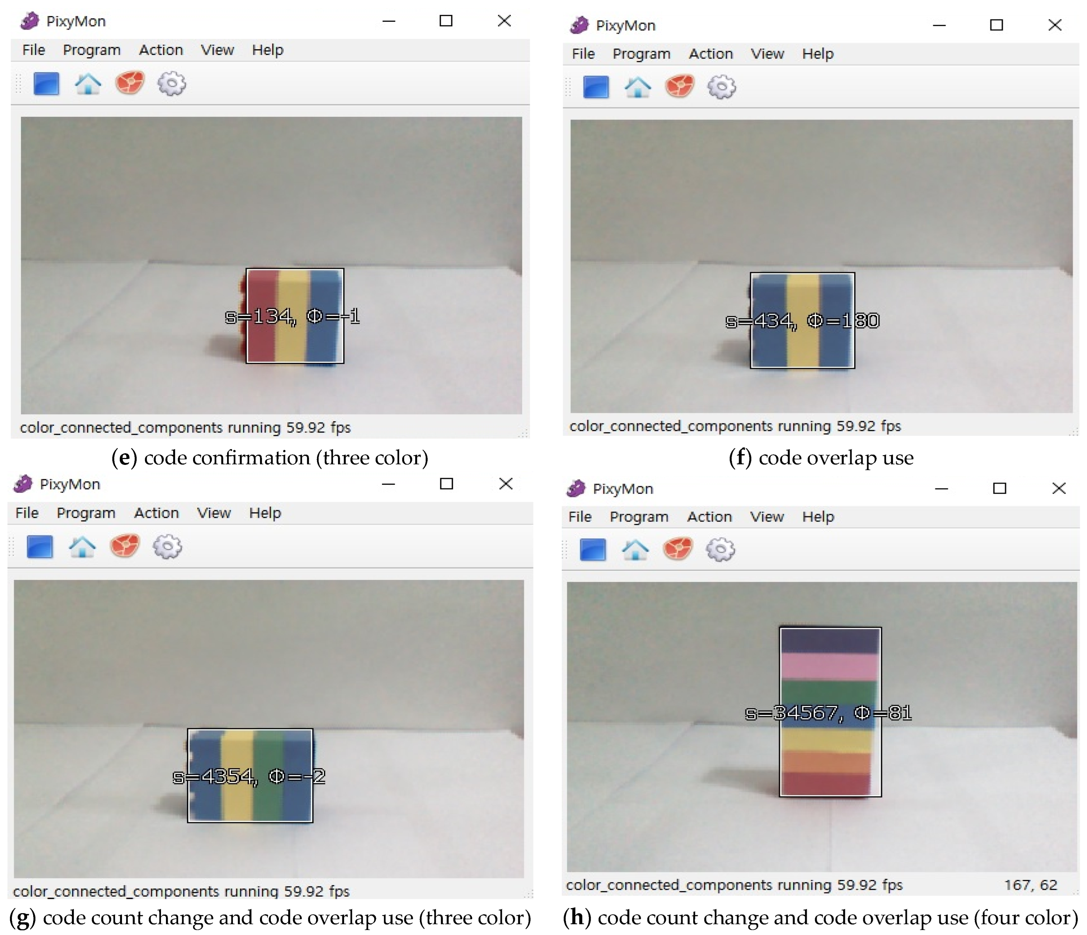
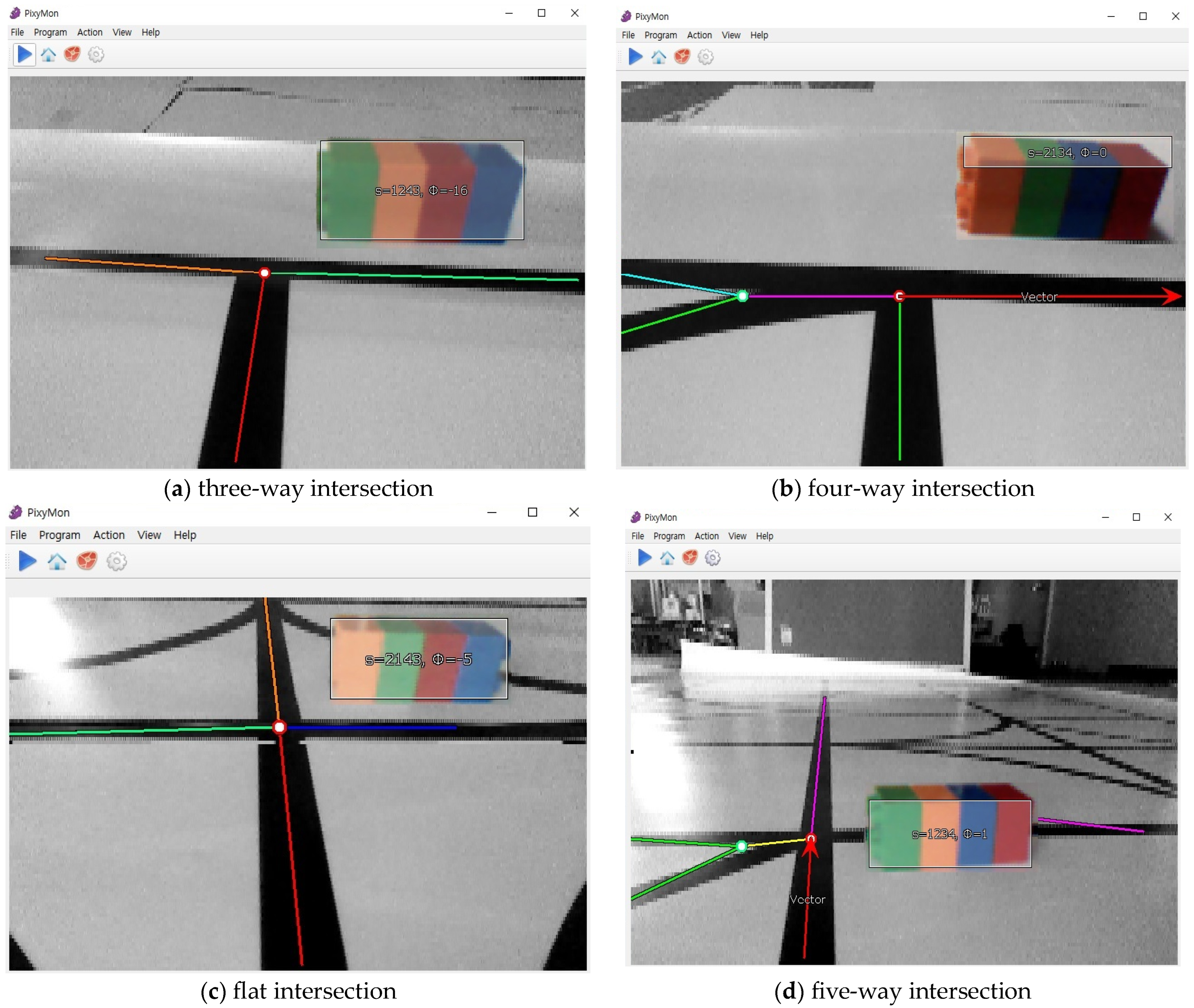
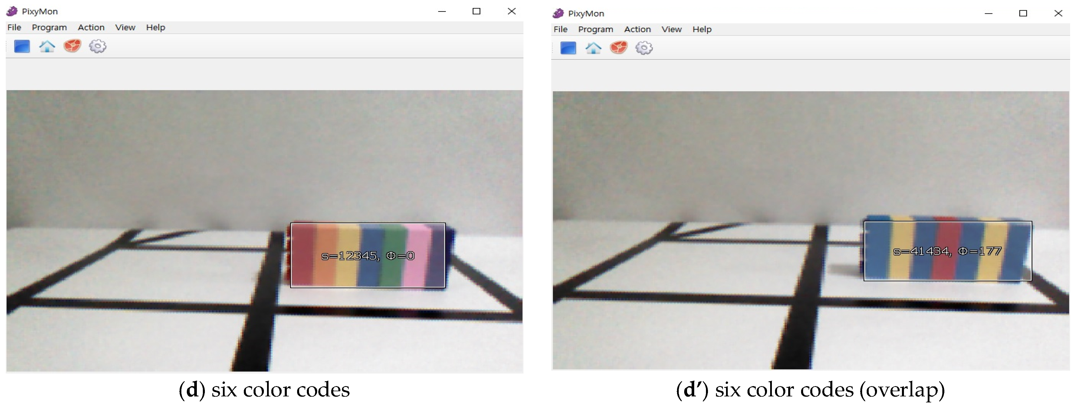
3.2. Color Code
4. Experimental Results
5. Conclusions
Author Contributions
Funding
Institutional Review Board Statement
Informed Consent Statement
Data Availability Statement
Conflicts of Interest
References
- Vis, I.A. Survey of research in the design and control of automated guided vehicle systems. Eur. J. Oper. Res. 2006, 170, 677–709. [Google Scholar] [CrossRef]
- Le-Anh, T.; De Koster, M.B.M. A review of design and control of automated guided vehicle system. Eur. J. Oper. Res. 2006, 171, 1–23. [Google Scholar] [CrossRef]
- Qui, L.; Hsu, W.J.; Huang, S.-Y.; Wang, H. Scheduling and routing algorithms of AGVs: A survey. Int. J. Prod. Res. 2002, 40, 745–760. [Google Scholar] [CrossRef]
- Ho, T.-C. A dynamic-zone strategy for vehicle collision prevention and load balancing in an AGV system with a single-loop guide path. Comput. Ind. 2000, 42, 159–176. [Google Scholar] [CrossRef]
- Kim, S.H.; Hwang, H.; Kim, Y.-D.; Hahn, K.H. Development of operating rules for automated guided vehicle systems in heterarchical manufacturing system. J. Korean Inst. Ind. Eng. 1997, 2, 343–357. [Google Scholar]
- Moorthy, R.L.; Hock-Guan, W.; Wing-Cheong, N.; Chung-Piaw, T. Cyclic deadlock prediction and avoidance for zone-controlled AGV system. Int. J. Prod. Econ. 2003, 83, 309–324. [Google Scholar] [CrossRef]
- Borenstein, J. The OmniMate: A guidewire and beacon-free AGV for highly reconfigurable applications. Int. J. Prod. Res. 2000, 38, 1993–2010. [Google Scholar] [CrossRef]
- Caruso, M.J.; Smith, C.H.; Bratland, T.; Schneider, R. A new perspective on magnetic field sensing. Sensors 1998, 15, 34–46. [Google Scholar]
- Chan, C.-Y.; Tan, H.-S. Evaluation of Magnetic as a Position Reference System for Ground Vehicle Guidance and Control; California PATH Research Report, UCB-ITS-PRR-2003-8; Institute of Transportation Studies, UC Berkeley: Berkeley, CA, USA, 2003. [Google Scholar]
- Jing, L.; Yang, P. A Localization Algorithm for Mobile Robots in RFID System. In Proceedings of the 2007 International Conference on Wireless Communications, Shanghai, China, 21–25 September 2007; pp. 2109–2112. [Google Scholar] [CrossRef]
- Want, R.; Hopper, A.; Falcao, V.; Gibbons, J. The active badge location system. ACM Trans. Inf. Sys. 1992, 10, 91–102. [Google Scholar] [CrossRef]
- Priyantha, N.B.; Chakraborty, A.; Balakrishnan, H. The cricket location-support system. In Proceedings of the 6th Annual International Conference on Mobile Computing and Networking, Boston, MA, USA, 6–11 August 2000; pp. 32–43. [Google Scholar] [CrossRef]
- Gezici, S.; Tian, Z.; Giannakis, G.B.; Kobayashi, H.; Molisch, A.F.; Poor, H.V.; Sahinoglu, Z. Localization via ultra-wideband radios: A look at positioning aspects for future sensor networks. IEEE Signal Process. Mag. 2005, 22, 70–84. [Google Scholar] [CrossRef]
- Jung, K.-H.; Kim, J.-M.; Park, J.-J.; Kim, S.-S.; Bae, S.-I. Line tracking method of AGV using Sensor Fusion. J. Korean Inst. Intell. Syst. 2010, 20, 54–59. [Google Scholar] [CrossRef]
- Heo, S.W.; Park, T.-H. Localization system for AGVs using laser scanner and marker sensor. J. Inst. Control Robot. Syst. 2017, 23, 866–872. [Google Scholar] [CrossRef]
- Yang, K.-M.; Gwak, D.-G.; Han, J.-B.; Hahm, J.H.; Seo, K.-H. A study on position estimation of movable marker for localization and environment visualization. J. Korea Robot. Soc. 2020, 15, 357–364. [Google Scholar] [CrossRef]
- Choi, B.-H.; Kim, B.-S.; Kim, E.-T. Location estimation and obstacle tracking using laser scanner for indoor mobile robots. J. Korean Inst. Intell. Syst. 2011, 21, 329–334. [Google Scholar] [CrossRef] [Green Version]
- Kawano, T.; Hara, M.; Sugisaka, M. Generating target path for tracing a line before missing the traced line of dead angle of camera. In Proceedings of the 2006 SICE-ICASE International Joint Conference, Busan, Republic of Korea, 18–21 October 2006; pp. 5286–5289. [Google Scholar] [CrossRef]
- Lee, J.-H.; Jung, K.-H.; Kim, J.-M.; Kim, S.-S. Sensor fusion of localization using Unscented Kalman Filter. J. Korean Inst. Intell. Syst. 2011, 21, 667–672. [Google Scholar] [CrossRef]
- Beccari, G.; Caselli, S.; Zanichelli, F.; Calafiore, A. Vision-based line tracking and navigation in structured environments. In Proceedings of the 1997 IEEE International Symposium on Computational Intelligence in Robotics and Automation CIRA’97. ‘Towards New Computational Principles for Robotics and Automation’, Monterey, CA, USA, 10–11 July 1997; pp. 406–411. [Google Scholar] [CrossRef]
- Man, Z.G.; Ye, W.H.; Zhao, P.; Lou, P.H.; Wu, T.J. Research on RFID and vision based AGV navigation. Adv. Mat. Res. 2010, 136, 298–302. [Google Scholar] [CrossRef]
- Jang, J.Y.; In, C.H. Design and Implementation of AGV-UNO-CAR Using a Line Scan Algorithm. J. Korean Inst. Commun. Inf. Sci. 2021, 46, 1346–1354. [Google Scholar] [CrossRef]
- Kim, S.H.; Lee, H.G. Implementation of Pattern Recognition Algorithm Using Line Scan Camera for Recognition of Path and Location of AGV. J. Korea Indust. Inf. Sci. 2018, 23, 13–21. [Google Scholar] [CrossRef]
- Lee, G.W.; Lee, H.; Cheong, H.W. Object Detection of AGV in Manufacturing Plants using Deep Learning. J. Korea Inst. Commun. Eng. Sci. 2021, 25, 36–43. [Google Scholar] [CrossRef]
- Kim, C.M.; Cho, H.Y.; Yun, T.S.; Shin, H.J.; Park, H.K. RFID-based Shortest Time Algorithm linetracer. J. Korea Inst. Elec. Commun. Sci. 2022, 17, 1221–1228. [Google Scholar] [CrossRef]
- Arduino.cc. Available online: https://docs.arduino.cc/hardware/uno-rev3 (accessed on 14 August 2021).
- Pixy2 Camera. Available online: https://dronebotworkshop.com/pixy2-camera/ (accessed on 23 July 2021).
- Motor Driver Module-L298N. Available online: http://wiki.sunfounder.cc/index.php?title=Motor_Driver_Module-L298N (accessed on 23 July 2021).
- Byun, S.; Kim, M. A vision based guideline interpretation technique for AGV navigation. J. Korea Multimed. Soc. 2012, 15, 1319–1329. [Google Scholar] [CrossRef] [Green Version]
- Kim, M.H.; Byun, S. A guideline tracing technique based on a virtual tracing wheel for effective navigation of vision-based AGVs. J. Korea Multimed. Soc. 2016, 19, 539–547. [Google Scholar] [CrossRef] [Green Version]
- Gonzales, R.C.; Woods, R.E.; Eddins, S.L. Digital Image Processing Using MATLAB; Pearson/Prentice Hall: Upper Saddle River, NJ, USA, 2004. [Google Scholar]
- Cheng, H.D.; Jiang, X.H.; Sun, Y.; Wang, J. Color image segmentation: Advances and prospects. Pattern Recognit. 2001, 34, 2259–2281. [Google Scholar] [CrossRef]
- Lee, J.S. Velocity measurement of fast moving object for traffic information acquisition. J. Korean Inst. Commun. Inf. Sci. 2004, 29, 1527–1540. [Google Scholar]


| Index Number | Color 0 | Color 1 | Color 2 | … | Color N |
|---|---|---|---|---|---|
| Index 1 | red | red | Gold | … | random |
| Index 2 | orange | blue | Aqua | … | random |
| Index 3 | yellow | green | Brown | … | random |
| Index 4 | blue | orange | Gray | … | random |
| Index 5 | green | purple | Magenta | … | Random |
| Index 6 | pink | yellow | Navy | … | random |
| Index 7 | purple | pink | Pick | … | random |
Disclaimer/Publisher’s Note: The statements, opinions and data contained in all publications are solely those of the individual author(s) and contributor(s) and not of MDPI and/or the editor(s). MDPI and/or the editor(s) disclaim responsibility for any injury to people or property resulting from any ideas, methods, instructions or products referred to in the content. |
© 2023 by the authors. Licensee MDPI, Basel, Switzerland. This article is an open access article distributed under the terms and conditions of the Creative Commons Attribution (CC BY) license (https://creativecommons.org/licenses/by/4.0/).
Share and Cite
Jang, J.-Y.; Yoon, S.-J.; Lin, C.-H. Automated Guided Vehicle (AGV) Driving System Using Vision Sensor and Color Code. Electronics 2023, 12, 1415. https://doi.org/10.3390/electronics12061415
Jang J-Y, Yoon S-J, Lin C-H. Automated Guided Vehicle (AGV) Driving System Using Vision Sensor and Color Code. Electronics. 2023; 12(6):1415. https://doi.org/10.3390/electronics12061415
Chicago/Turabian StyleJang, Jun-Yeong, Su-Jeong Yoon, and Chi-Ho Lin. 2023. "Automated Guided Vehicle (AGV) Driving System Using Vision Sensor and Color Code" Electronics 12, no. 6: 1415. https://doi.org/10.3390/electronics12061415