1. Introduction
Metasurface technology is now seeing widespread application in the realization of novel antennas and devices, as well as in the creation of smart electromagnetic environments. Since metasurfaces can also be reconfigured in real time, the technology referred to as a reconfigurable intelligent surface (RIS) or large intelligent surface (LIS, with reference to the electrically large size) has emerged as a promising option to dynamically “customize” the environment and therefore the propagation channel [
1,
2].
A metasurface is a thin structure consisting of a substrate made of an insulating layer with a distribution of electrically small (i.e., smaller than the wavelength) metal or dielectric patches printed on it; these are called meta-atoms. Meta atoms can have various shapes, such as spiral, square, rectangular, H-shape, etc., and their shape and size vary over the surface in order to achieve the desired effect on the wavefront of the reflected or transmitted wave when the surface is illuminated by an incident wave within a given frequency range, including non-specular (or anomalous) reflection, focalization, polarization change, etc. An alternative realization is achieved through a more traditional reflect-array or transmit-array technology, where antenna elements, usually half a wavelength apart from each other, are connected to variable reactive loads (e.g., varactors).
Aside from the circuitry necessary to reconfigure them—usually consisting of a control network with PIN diodes or varactors—RISs are usually passive, relay-type devices that must be mounted in strategic locations or on a building’s surfaces: in the latter case, they are usually referred to as “Smart Skins”.
From a technological standpoint, the most common type of metasurface is the so-called phase gradient metasurface (PGM) or periodic metasurface, which is designed to apply a constant phase gradient to the reradiated wave by means of a periodic meta-atom pattern along a given direction on the surface, therefore realizing anomalous reflection or refraction (transparent metasurfaces) along the same direction. If the applied phase gradient is not constant and varies slowly over the surface with respect to the wavelength, the metasurface is defined locally periodic.
Metasurfaces are defined as “local” if their effect on the reradiated wave, as well as the power balance between the incident, dissipated, and reradiated power fluxes at a given surface spot, only depends on the local characteristics of the metasurface, i.e., there is no relevant power transfer between electrically distant surface elements through surface waves propagating within the substrate.
Unfortunately, periodic or locally periodic metasurfaces do not reradiate only a single wave in the desired direction, but rather reradiate a spectrum of parasitic waves corresponding to the propagating Floquet modes. Parasitic modes are a function of the incident direction and can be suppressed at the expense of power efficiency [
3]. Recent metasurface technologies can exploit surface-wave propagation to realize non-local designs that can suppress parasitic modes without sacrificing power efficiency, in addition to realizing quasi-perfect anomalous reflectors [
3]. However, their ideal behavior only takes place for a single illumination direction of the design. Moreover, real-world RISs have a finite size that generates edge diffraction, while illumination conditions can, far from being far-field, be plane-wave conditions with a single incident direction.
Given the above-mentioned considerations, it is evident that:
- (i).
Electromagnetic propagation in the presence of a metasurface is a complex process that involves microscopic propagation phenomena (coupling between meta-atoms, surface waves, etc.) within the metasurface structure.
- (ii).
Metasurfaces, and therefore RISs, show far-from-ideal behavior: in fact, they show dissipation, diffraction, diffuse scattering, and multiple reradiation modes, even though only one of these is usually the desired effect.
Although the phenomena detailed in (i) are crucial for the small-scale application of metasurface technology to antennas and devices, only the overall, macroscopic behavior in terms of radiative near-field and far-field scattering is relevant to their large-scale application to wireless networks. Full-wave electromagnetic methods that are necessary for proper simulation of the microscopic propagation phenomena (i) are impractical for the design and simulation of large-scale applications due to their computational burden.
At the same time, the analysis of the actual behavior of an RIS within a wireless network and its impact in terms of coverage or spectral efficiency requires electromagnetically consistent, realistic models that can take into account the non-ideal phenomena (ii), the RIS’s main parameters, the wave transformations it applies, and its size, losses, illumination conditions, and reradiation distance [
1]. In particular, accurate RIS modeling is crucial to addressing the question of whether RIS technology can really be advantageous in terms of good performance and lower costs with respect to solutions based on network densification.
Motivated by these considerations, some research investigations have recently addressed the “macroscopic modeling” of finite-size metasurfaces based on different methods and modeling assumptions, with the aim of simplifying or bypassing the description of microscopic phenomena (i) and therefore minimizing computational complexity, while retaining an accurate radiative near-field and far-field description including non-ideal mechanisms (ii).
Some studies propose equivalent circuit models where meta-atoms and tuning devices are replaced by their equivalent circuit representations [
4]. Then, microwave network theory is applied to compute the reflection coefficient and the far-field pattern of the RIS. However, these methods start from a detailed description of the meta-atom layout and require electromagnetic simulation to derive their circuit representations. The study reported in [
5] explicitly accounts for the existence of multiple directions of propagation based on Floquet’s theory for the case of periodic metasurfaces. The main analysis is specialized to the far field of the RIS. In [
6], a ray-based representation of scattering from a finite-size RIS, assumed to be locally periodic, is developed. In [
7], physical optics and the vector Huygens principle are applied to model near-field and far-field scattering from a finite-size RIS. Although not as rigorous as those mentioned above, the model proposed in [
8] is simpler and also takes into account the presence and impact of diffuse scattering that may be caused by, e.g., design tradeoffs, construction inaccuracies, or phase errors with respect to the value of design, which are common when using control networks with discrete-phase rotation states.
Several studies, such as [
9,
10,
11,
12,
13], use the ideal antenna array theory to model and/or to optimize path loss and channel capacity in RIS-assisted wireless networks, assuming that the RIS is realized as a reflect array of independent antenna elements with a given radiation pattern and a complex reflection coefficient. In [
13], under similar assumptions, the problem of optimizing coverage in indoor networks over non-line-of-sight (NLoS) locations using multiple RIS is addressed. However, the approach of the previously mentioned studies cannot be applied to the case of RIS realized using metasurface technology with electrically small unit cells, and it neglects antenna coupling and scattering effects.
In this paper, we use the approach detailed in [
8], section II.B, which describes the RIS through a parametric power balance and a spatial modulation coefficient to compute the reradiated field with a Huygens-based “Antenna-Array-Like” (AAL) method; we carry out realistic RF coverage assessments in an indoor environment. Although the approach is seemingly similar to the cited studies [
9,
10,
11,
12,
13], it is designed to be applied in a way that is electromagnetically consistent to any kind of RIS, regardless of the technology, and is able to account for parasitic modes, dissipation, and diffuse scattering. The approach is based on a simple theory and is limited to single-bounce scattering. However, we embedded it in a 3D ray-tracing (RT) tool and, leveraging radio link reciprocity, we take into account multiple-bounce rays with RIS scattering as the first or the last interaction. Then, we used the resulting enhanced ray tracing model to carry out some evaluations of the RF coverage gain that can be achieved in a reference indoor environment; we used RIS panels configured as anomalous reflectors or as a focalizing reflectors, as shown in
Section 3. We found that a gain of about 10–15 dB can be obtained in blind-spot locations with proper RIS placement and configuration, even using lossy phase-gradient metasurfaces.
2. Antenna-Array-like Macroscopic Modeling
The modeling approach presented here is a simplified version of the parametric approach described in [
8], which can nevertheless give realistic results if properly tuned. As a first step, the RIS is discretized into surface elements. For the generic element at position (x, y) on the surface, a local power balance is defined so that the power amplitude
mn of each of the reradiation modes of the metasurface relative to the incident power
Pi is consistently defined:
where
τ represents the fraction of the incident power that is dissipated into heat, S
2 is the fraction of the incident power that is scattered due to design or realization imperfections, and R
2 accounts for the corresponding attenuation of reradiation modes according to the effective roughness scattering model [
14]. Note that, typically, one of the
N reradiation modes in (1) is actually specular reflection and, therefore, can be taken into account using the traditional ray-tracing method, as highlighted in [
8]. Additionally, all parameters in (1) are in theory functions of position (x, y) due to the different illumination direction of the different surface elements. Under far-field illumination conditions, however, the incident wave can be assumed plane, and therefore the parameters in (1) will be constant over the whole RIS. Considering that a perfectly smooth RIS would have
S = 0 and
R = 1 but the reradiation and dissipation parameters would remain the same, the following relationship can be easily obtained [
8]:
The parameters in (1) and (2) can be defined using Floquet’s theory for locally periodic metasurfaces, measured on a prototype, or computed using electromagnetic simulation. In the first case, Floquet’s theory directly provides the amplitudes m
n of all parasitic modes. Otherwise, far-field measurement or simulation on a RIS sample can provide the scattering pattern to be used to identify parameter values either using visual inspection—each reradiation mode corresponds to a scattering lobe whose amplitude is proportional to its m-parameters—or through a parameter-matching procedure. Then, the scattering parameter
S can be estimated or measured in a similar way as with ordinary surfaces [
14], while the last parameters and R and
τ can finally be derived from Equations (1) and (2). Once the parameters are defined, the corresponding field contributions must be computed for each one of the
N reradiating modes. With reference from now on to the generic n-th reradiation mode, and dropping the footer “
n” for simplicity, the contribution of the metasurface to the reradiated field can be described through a “spatial modulation coefficient”, which can also be thought as a local reflection coefficient, the expression of which is:
where
and
are the “amplitude and phase profiles” that the RIS imposes on the reradiated field, respectively. Note that the amplitude term
A(
x,
y) is introduced to account for power transfer effects due to surface waves in non-local metasurfaces:
A(
x,
y) is normalized as it must satisfy
;
for phase-gradient metasurfaces.
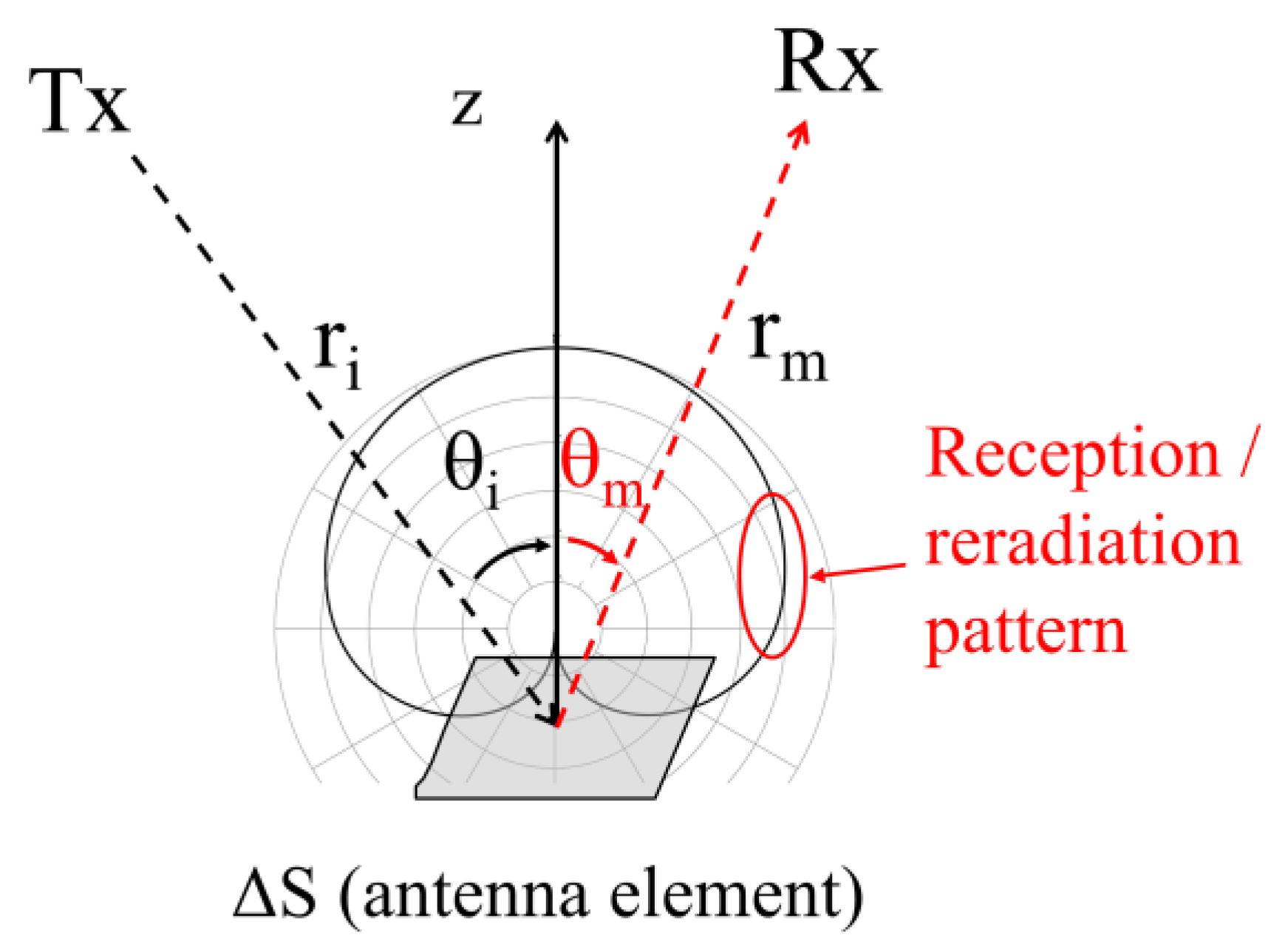
In order to compute the reradiated field of the finite-size metasurface, we adopt a discrete Huygens-based approach that corresponds to modeling the metasurface as a 2-dimensional antenna array. We discretize the RIS into surface elements Δ
S and, for simplicity, we assume equal spatial sampling; therefore, Δ
S = Δ
xΔ
y = Δ
l2. Each element is modeled as an ideal aperture antenna element that receives the incident power
Pi and reradiates a spherical wavelet of power
Pm =
mA2Pi according to a given (re)radiation pattern. All the wavelets generated by all surface elements combine coherently according to their amplitude and phase to generate the overall reradiated wave front. In order to avoid grating lobes, it must be the case that:
This approach is based on classic antenna theory and on the concepts of effective aperture
Am and of antenna directivity gain
for the reception and the reradiation of each antenna element, respectively. The radiation pattern and therefore
Dm and
Am must satisfy the following physical constraint:
If (5) were violated, the amount of power received and reradiated by a square meter of an indefinite RIS surface could be larger than the power incident on it, which is absurd.
Since an aperture antenna must have a directivity gain greater or equal to 3 [
15], it must be true that:
If we combine (4) and (6), we conclude that the only possible spacing step that is physically sound is
. While the formulation derived in [
8] is general, as it can accommodate any radiation pattern that satisfies the foregoing constraints, here, we only consider an antenna that naturally complies with those constraints of the Huygens source, whose directivity is
Dm = 3 and whose antenna pattern is:
The electric field intensity
of the generic antenna element must therefore be:
where
is an amplitude factor to be defined (see below) and which must include the spatial modulation coefficient. With reference to
Figure 1, in order to satisfy the power balance at the generic surface element, we necessitate that:
If the primary source is a transmitter with transmitted power and antenna gain
Pt and
Gt, respectively, we have:
Therefore, Equation (9) can be easily solved to yield the closed-form solution:
and, therefore:
Equation (11) gives the reradiated field intensity of the generic surface element of reradiation coefficient m.
It is important to note that, since the maximum effective aperture of the Huygens source (for θ
i = 0) is
, and for Δ
l = λ/2 we have:
the Huygens antenna element will not exactly capture the whole power incident on Δ
S; therefore, the field (11) will correspond to a reradiation coefficient slightly lower than
m A2. This small gap can be compensated by multiplying the field intensity (11) by
, or by considering a surface discretization with a slightly smaller spacing:
Expression (11) only gives the field intensity, as it is derived from a simple power balance. The phase of coefficient (3) must now be applied, as well as the phase distribution of the incident field on the metasurface, which is important in near-field conditions. Moreover, a proper polarization vector must be applied to account for the polarimetric properties of the reradiated field. Therefore, the coherent field contribution of the discrete element located at (
x,
y) to the field in P can be written as:
Equation (14) can be rewritten in the following way by using expression (3) of the spatial modulation coefficient:
The total reradiated field at P can be expressed as a coherent summation of the discrete field contributions Δ
Em:
Moreover, the sum is performed on
NX ×
NY antenna elements, where
and
are
LX and
LY, the linear dimensions of the surface along and
x and
y, respectively. Although the number of elements to be considered can be large, the computation of Equation (16) is easily parallelizable on today’s parallel computing platforms such as graphic processing units (GPU) or multi-core CPUs, in order to achieve good computational speeds.
In essence, the antenna-array-like (AAL) model is a parametric, simple model that relies on the proper parametrization of the metasurface to describe the reradiated field with a simple formula. In reference far-field illumination cases, parameters m, Xm, and can be easily defined and considered constant over the surface.
3. Results
The AAL model described in
Section 2 was embedded into a 3D RT simulator developed at the University of Bologna [
16]. Since the AAL model expresses anomalous reflections from the RIS as a sum of multiple contributions from each one of its surface elements, and not as a set of rays that satisfy geometrical optics rules, the AAL model does not seamlessly “blend” within the RT algorithm: anomalous reflection can only be handled in a straightforward way as the last interaction of the ray chain. Nevertheless, exploiting the reciprocity of the radio link, and by swapping the Tx and Rx positions for the purpose, we were also able to take into account multiple-bounce rays experiencing RIS scattering as the first interaction of the chain. The field contributions of such rays are added to the final result in order to obtain a realistic estimate of RF coverage in the presence of an RIS.
As a benchmark, we first consider a typical environment that could take advantage of the presence of an RIS: a simple L-shaped corridor scenario with concrete walls (
Figure 2). To derive conservative evaluations, we considered RIS realization using lossy, PGM metasurfaces. Of course, with the use of more sophisticated non-local metasurfaces or more expensive reflect array schemes, slightly better performance levels might be achieved. The TX was located at the bottom end of one of the two corridor branches, and we aimed to investigate the RF coverage level on the other corridor branch, at the frequency of 28 GHz. The TX antenna is a directive antenna with a half-power beamwidth of 60° in the horizontal plane pointed towards the end of the corridor; meanwhile, for RXs, an ideal omnidirectional half-wavelength antenna is considered. The TX antenna transmits a signal with EIRP = 3 dBm in the direction of maximum radiation. In the simulations, we placed a 1 m × 1 m RIS configured as anomalous reflector in the top wall of the first corridor branch, opposite to the TX location. RT simulations were carried out with a maximum of six reflections, double transmission, single diffraction, a combination of reflection and diffraction (one reflection + one diffraction in the same ray), and single diffuse scattering, modeled through the ER approach [
14].
Figure 3 shows the coverage map for the standard case where no RIS was used to improve coverage. It is clear that, except for the RX locations in LoS condition w.r.t. TX, the power level is quite low, especially for the farthest locations, where it falls below the noise floor (assumed here to be equal to −100 dBm). In fact, both the transmission through concrete walls and the diffraction on the corner are very low at the considered mm-wave frequency.
Figure 4,
Figure 5 and
Figure 6 show the coverage map in the presence of the RIS, assumed as a lossy, PGM anomalous reflector with nominal reflection angles of 40°, 60°, and 80°. In the RT simulations, only the “desired” reradiation mode was considered, but the
m parameter of the desired mode was properly set to take into account the progressive reduction in the efficiency of the RIS as the reflection angle increases, according to what [
3] reported for a PGM case (see
Table 1). Moreover, a scattering parameter
S = 0.5 was considered for the RIS, as well as for the corridor walls.
We also analyzed coverage in the case of an RIS configured as a “focusing lens”, as shown in
Figure 7. For these purposes, we used the formula reported in [
8], section IV, case 2. In such a case, the values
m = 1 and
S = 0.5 have been considered in the simulation. A good, localized coverage level, similar to the case of an anomalous reflector with θ
m = 80°, is obtained when the focus point is located in the center of the side corridor, as shown in
Figure 7a. However, the best coverage, both in terms of the mean power level and the standard deviation of the power, is obtained by orienting the focusing RIS toward the end of the side corridor, i.e., the farthest point from the TX. In fact, using this method, we observed a power boost in the RX points where coverage is more difficult to achieve, while closer RXs can be reached through multiple reflections on the side walls.
All results for the L-corridor case are summarized in
Table 2, showing the average power level, the standard deviation of the Rx power, and the percentage of receivers in outage condition (i.e., with Rx power lower than the noise floor of −100 dBm). It is evident that, when the RIS is configured with nominal reflection angles greater than 60°, and despite the reduction in the RIS efficiency, the average power level is increased by more than 10 dB and the coverage is much more uniform, compared to the case where no RIS is used. Additionally, the number of Rx locations in outage conditions is reduced to zero. The performance of the RIS configured as a focusing lens is similar to the case of the anomalous reflector at 80°, with a slightly better mean power level and a slightly worse standard deviation.
Finally, in
Figure 8, the CDF of the received power is shown for 4 different cases: no RIS; RIS with a reflection angle of 40°; RIS with a reflection angle of 80°; and RIS configured as a focusing lens oriented toward the end of the side corridor.
The results obtained for the L-corridor case can be extended in a straightforward way to the case of a T–shaped intersection. For example, good coverage is yielded in all the Rx locations when using two RISs placed side by side in the center of the intersection with a symmetric configuration in order to illuminate both branches of the side corridor, as shown in
Figure 9. Here, the coverage map of the T–corridor with no RIS usage is compared with the case of 2 RIS panels pointing at +80° and −80°, respectively.
As a last benchmark scenario, we have studied the case of a single room where the TX and receivers are not visible to each other, being separated by a metal partition wall (
Figure 10): our aim was to investigate coverage along a line of Rx points located on the other side of the room In such a case, we have considered a lower frequency band (3 GHz), and ideal, half–wave dipole antennas at both Tx and Rx side.
In
Figure 11, RF coverage obtained with RT simulation along the Rx line is shown, comparing the standard scenario (no RIS) with two different cases: (a) bottom wall consisting of a row of eight anomalous reflectors of size 1 × 2 m
2 and configured with different anomalous angles, optimized for uniform coverage along the RX line; (b) a single focusing reflector of sized 4 × 2 m
2 placed in the center of the bottom wall, configured to focus the reradiated wave toward the center of the Rx line. As was true for the L–corridor case, the efficiency of the RIS—i.e., the value of the
m parameter of desired reradiation mode—is reduced as the RIS reflecting angle increases, in accordance with the model reported in [
3], and a value of 0.5 is assumed for the
S parameter.
The results clearly show a significant improvement: in particular, an average increase of 15 dB is observed in the first case, together with a reduction in the standard deviation of the power level, with significant coverage improvement close to the partition wall, where coverage was poor. In the second case, a gain of almost 20 dB is achieved around the focal point, which of course could be changed in real-time if the RIS were reconfigurable.
It is worth noting that the gain levels we found in the present work, with respect to the case without RIS, are considerably lower overall than those shown in other studies, where a gain of several tens of dB is achieved with the proper placement of optimized RIS panels [
13]. This may be due to multiple reasons, including the different environment topologies and frequencies, the more ideal RIS modeling assumptions, and, above all, the use of ad hoc optimization algorithms for RIS element weights for the specific mobile locations, which we did not consider in the present work. Another reason is that, especially in the case of a focusing RIS, the attainable power gain strongly depends on the RIS size; however, in indoor scenarios, the size cannot be very large: in this work, we assumed an RIS area of 1 m
2, which can be regarded as a representative case for small and medium indoor environments. Overall, our assessment is representative of the use of low-cost static RIS that can be pre-configured and deployed in typical indoor environments based on the specific installation topology (L-shaped corridor, T-shaped corridor, etc.), and which do not require real-time estimation of the channel state.
4. Conclusions
The macroscopic, general-purpose model for scattering from finite-size metasurfaces presented in [
8] (section III.B) was here embedded in a 3D ray-tracing simulator. Then, simulations for a lossy, phase-gradient anomalous reflector were carried out in a reference indoor scenario with typical material and RIS parameters, in order to assess the use of a pre-configured RIS to improve coverage. Realistic values for RIS efficiency were considered based on the existing literature and taken into account in the model, as were other parasitic effects such as diffuse scattering.
The results showed that, in simple benchmark scenarios such as L–corridors or T–shaped intersections, a gain of about 15 dB in average received power can be attained using a traditional, phase-gradient RIS configured as anomalous reflector with a reflection angle of 70°. The results also showed that reflection angles greater than 60° are necessary to achieve a uniform coverage and eliminate RX locations in outage conditions, despite the higher losses of the RIS when it is configured for high anomalous angles. Similar results were obtained in U–shaped scenarios: for example, in the case of two adjacent rooms separated by a non-penetrable partition wall, where the use of a single transmitter and a row of anomalous reflectors configured with different angles allowed for good coverage on the other side of the U. Moreover, good performance is also obtained when the RIS is configured as a focusing lens; in such a case, higher power levels are obtained in the desired illumination spot, but the performance also remains acceptable in the surrounding Rx locations, with an average power level similar to the case of the anomalous reflector, with a similar or slightly worse standard deviation, depending on the case.
Our results are representative of the use of low-cost static RIS that can be pre-configured based on reference installation topologies (L–shaped corridor, T–shaped corridor, etc.) and which do not require real-time estimation of the channel state. Furthermore, given the very conservative case considered, our results are of general interest due to the fact that a significant coverage gain is obtained in a realistic environment, even when using a readily available and inexpensive technology. Of course, different types of realistic metasurface designs can be simulated with the considered model, simply by changing its input parameters and spatial modulation function. The model is well suited for the case where the RIS is the last object of the interaction chain; however, by using the reciprocity of the link, we extended the prediction to include the paths where the RIS is at the beginning of the interaction chain. Future studies will address the implementation of a more general fully ray-based model, allowing us to consider rays where the RIS can be located at any stage of the interaction chain and significantly improving computation efficiency.


