Article

Passive Backstepping Control of Dual Active Bridge Converter in Modular Three-Port DC Converter

School of New Energy and Power Engineering, Lanzhou Jiaotong University, Lanzhou 730070, China
*
Author to whom correspondence should be addressed.
Electronics 2023, 12(5), 1074; https://doi.org/10.3390/electronics12051074
Submission received: 8 January 2023 / Revised: 16 February 2023 / Accepted: 17 February 2023 / Published: 21 February 2023

Abstract

:
A dual active bridge (DAB) converter in a modular three-port DC converter is the key equipment to connect distributed energy and energy storage units and realize its efficient and large-scale utilization. When a DAB converter with traditional control is disturbed by the input voltage of distributed energy sources, some problems occur, such as large fluctuation of load voltage and slow dynamic response. In order to address such problems, this paper firstly starts with the single-phase shift control of the DAB converter, establishes the dynamic mathematical model of the DAB converter according to the nonlinear characteristics of the converter, transforms it into the passive form of Euler–Lagrange (E-L) model and designs the passive controller based on the analysis of the passive nature and stability of the converter, in order to improve the energy dissipation rate and ensure the global stability of the system. Secondly, in conjunction with the backstepping control, a passive backstepping controller is designed with the goal of shifting the comparison to eliminate errors caused by input disturbances and achieve fast-tracking of the reference voltage. Finally, a DAB simulation model based on passive backstepping control is established in Matlab/Simulink. By selecting the appropriate injection damping value, it is compared with traditional PI control and passivity-based control strategy, and the effectiveness of forward and reverse power transmission modes of the DAB converter under passive backstepping control is verified. The results show that the DAB converter with passive backstepping control has better dynamic performance and stronger robustness after sudden changes in input voltage.

1. Introduction

With the proposal of China’s “3060” dual carbon target, China’s current fossil-based energy sources have brought great challenges and opportunities, and it is foreseeable that access to a high proportion of new energy sources, such as solar and wind power, will become an important part of the AC/DC system [1]. Three-port DC converters, also known as energy routers or power electronic transformers [2,
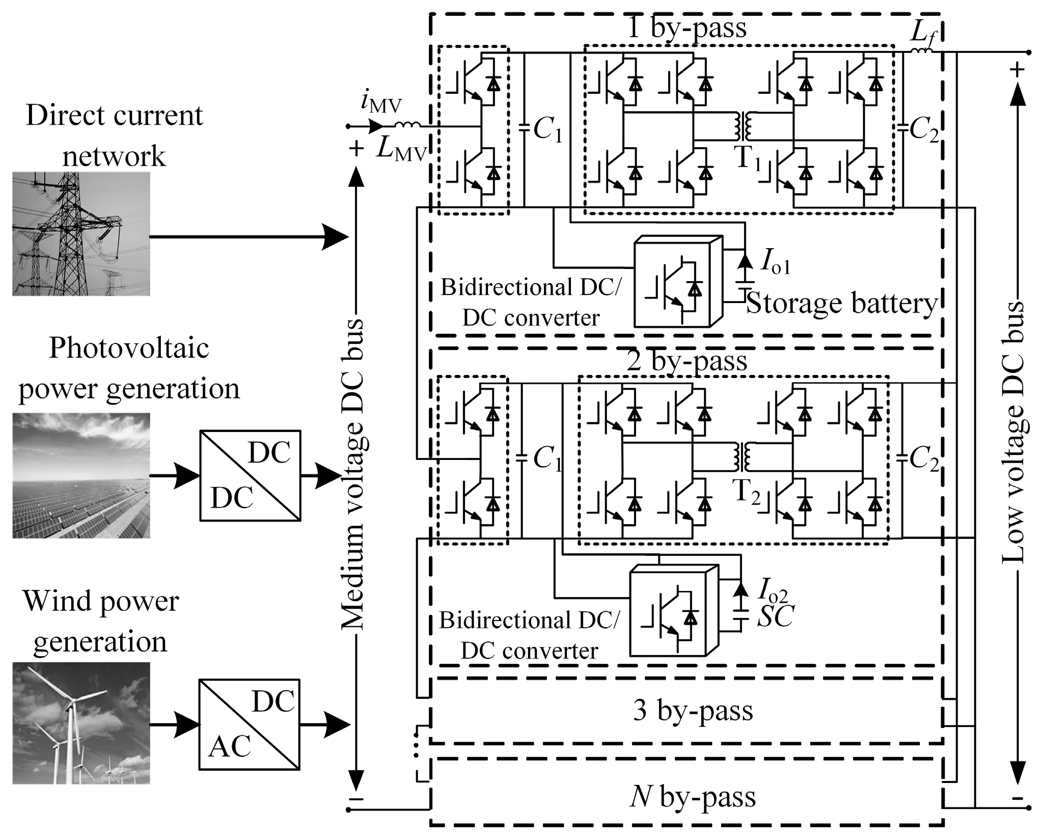
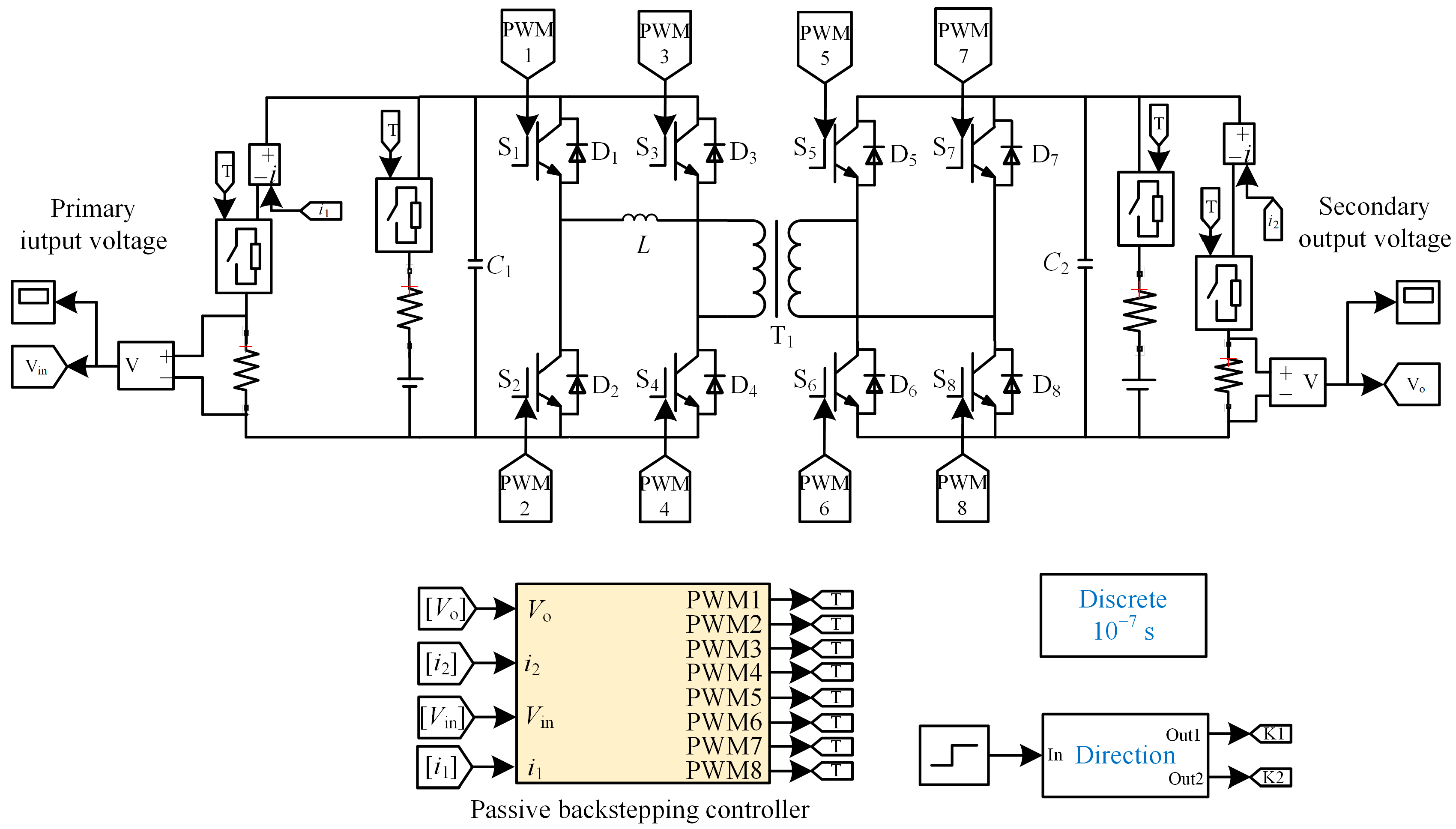
3], which enable access to renewable energy, energy storage unit access, power control and regulation, involve theories and technologies that have become a hot topic of current research. As the key equipment connecting distributed energy sources and energy storage units, the three-port DC converter can achieve electrical isolation on the high and low voltage side and provide interfaces to different voltage levels, power control and other functions. The individual converter is limited by disadvantages such as low voltage, power levels and small capacity, so most modular combinations are used to form modular three-port DC converter with inputs in series and outputs in parallel, as shown in Figure 1.
The modular three-port DC converter combines the half-bridge sub-module, dual active bridge (DAB) converter and energy storage unit module. The DC grid provides energy support for the entire converter, and wind power generation and photovoltaic power generation can be connected to the medium voltage DC bus via the converter according to demand. The inclusion of an energy storage unit, which charges and discharges according to its own charge state when the distributed energy power output is surplus or insufficient, maintains the stability of the low-voltage DC bus supply and improves the flexibility of converter operation. The output stage DAB converter, which carries the conversion and bi-directional transfer of energy at different voltage levels, is the core part of the modular three-port DC converter. DAB converter is widely used in hybrid electric vehicles [4] and DC microgrids [5,6] and have a broad application prospect in the field of electrified traction power supply systems [7] due to their advantages of bi-directional energy transmission, high transmission power and easy modular expansion. The above fields require flexible control of output voltage and output power to improve power quality, which puts high demands on the controller performance of the converter.
During the energy transfer and conversion of the DAB converter, an accurate, robust and fast dynamic response is required to improve the dynamic response speed of the converter during load switching or input voltage instability and to quickly track new operating modes in a timely manner [8,9]. Reference [10] combined the traditional inductor current peak control and single phase shift control to form a boundary control method by sampling the inductor current. This method significantly speeds up the dynamic response of the DC-DC converter when the load changes suddenly, but the control process of this method is too complex, requiring as many as five Hall sensors, and too many detected variables increase the calculation. Reference [11] proposes a dual-band peak current controller with feedforward compensation. It not only has a very fast dynamic response but also can dynamically adjust the output voltage. However, this method does not verify the reverse transmission mode and does not meet the requirements of bidirectional power transmission of the converter. Kan et al. [12] proposed a multivariable solution algorithm based on the principle of high-frequency AC voltage rise and fall, which does not rely on the accurate feedback of current sensors, reduces the current stress of switching devices and ensures efficient conversion of converters. When combined with the above literature, the existing research mainly uses the traditional control theory to design the controller of the DAB converter, but the primary and secondary sides of the converter contain controllable degrees of freedom, which often has poor dynamic characteristics and is difficult to adapt to multi-working conditions.
In order to overcome the above problems, relevant scholars have proposed sliding mode control [13], model predictive control [14] and other control methods, one after another. They use nonlinear control algorithms to design the output voltage or current controller of the DAB converter, which has strong robustness to input uncertainties and disturbances. Reference [15] applies the fuzzy logic control strategy to the battery charging current control of the DAB converter, in which no previous information about the system parameters is required. Askarian et al. [16] adopted a new digital control system, including a hybrid modulator and a new compensator. Based on the geometric sequence control algorithm, the compensator can achieve a fast transient response and accurate output current/voltage regulation. In [17], by analyzing the transmission characteristics of the DAB converter and taking the traditional phase-shift control as an example, a model predictive control strategy based on the state space average model of the converter was established to eliminate the problem of unbalanced transmission power. The control strategy in the above literature greatly improves the dynamic response speed of the DAB converter, but it also has the problem of relying on accurate sampling information at the current time, and a slight error affects the follow-up and overall control effect. In addition, nonlinear control rarely involves the converter working under the condition of input voltage fluctuation.
As an important control method of nonlinear systems, passivity-based control (PBC) is easy to design and has strong robustness to external changes in output dynamic response. It is widely used in nonlinear systems such as modular multilevel matrix converters and grid-connected inverters to reduce control parameters, improve dynamic response speed and enhance anti-interference ability. Cheng et al. [18] introduced passivity-based control to a permanent magnet synchronous motor, which can quickly reach the desired stable value and has excellent dynamic performance. In reference [19], to improve the output voltage of the DC bus of a quasi-z-source three-level grid-connected inverter, passivity-based control was adopted, and 20 Ω injection damping was selected, which improves the dynamic characteristics and robustness of the system. In the design process of the above passive controller, the pursuit of global stability under nonsingular points sacrifices the transient performance of the system, and it is difficult to track external voltage disturbances quickly, which affects the overall control effect. To eliminate the influence of input changes, in [20], aiming at power fluctuations caused by load changes in an interconnected converter, on the basis of power outer loop control containing action threshold, an internal loop backstepping control (BSC) strategy based on interference observer was proposed to improve the resistance ability of microgrid to external impact, shortening the time to steady state. The authors of [21] organically combined the port-controlled dissipative Hamiltonian system with the backstepping control, effectively suppressed the interphase circulation of the modular multilevel matrix converter, ensured global stability and took into account the fast dynamic response. The backstepping control can quickly track the output voltage under external disturbances, which can effectively make up for the defects of passivity-based control. Therefore, the combination of backstepping control and passivity-based control can balance the control accuracy and response speed of the DAB converter and ensure the global asymptotic stability and robustness of the control system.
To improve the dynamic response of the output of the DAB converter and to achieve forward and reverse power transfer mode switching of the DAB converter, a passive backstepping control (PBSC) strategy based on the Euler–Lagrange (E-L) model is introduced into the DAB converter. First, the single-phase shift control and first-order dynamic mathematical model of the DAB converter are analyzed. The E-L model of the DAB converter is then established to satisfy the concept of passivity, the passivity-based control rate equation of the converter is derived, the passive controller is designed and the passive backstepping controller is finally designed by combining with backstepping control. Finally, the excellent characteristics of the passive backstepping control strategy are verified by Matlab/Simulink simulation.

2. Structure and Working Principle of DAB Converter

2.1. Topology of DAB Converter

The topology of the DAB converter is shown in Figure 2. The converter unit contains a rectifier bridge, an inverter bridge and a high-frequency isolation transformer. Where Uin is the input voltage of the DAB converter; Uo is the output voltage of the converter; C1 is the DC input capacitance of the DAB converter; C2 is the DC output capacitance of the DAB converter; L is the sum of the leakage inductance and the auxiliary inductance of the DAB converter converted to the primary side, which undertakes the storage and release of the system transient energy; i2 is the output current of the secondary side of the converter and i0 is the DC side of the converter load current; R is the equivalent load resistance at the output of the DAB converter; U1 and U2 are the primary and secondary AC voltages of the isolation transformer, respectively; and the variable ratio of the isolation transformer is N.

2.2. Working Principle of DAB Converter

For the DAB converter, the single-phase shift control contains only one shift compared to the other and is easily implemented and widely used. When the primary AC voltage is in phase ahead of the secondary voltage, the power is transmitted in the forward direction when D > 0. Conversely, the power is transmitted in the direction when D < 0. The waveform of the single-phase shift control of the converter is shown in Figure 3, where T is half the switching period, ton is the conduction time of the primary and secondary full bridges, D is the shift between U1 and U2, D = ton/T, and −1 < D < 1. In a steady-state operation, the transferred power [10] with single-phase shift control can be expressed as Equation (1).
P = N U in U o 2 f L D ( 1 | D | )
where f is the switching operating frequency of the converter.
It can be seen from Formula (1) that when D = 0.5, the maximum forward transmission power is reached, and the DAB converter usually works in the range of [−0.5, 0.5] to ensure that power can be transmitted in both forward and reverse directions.

3. E-L Model of DAB Converter

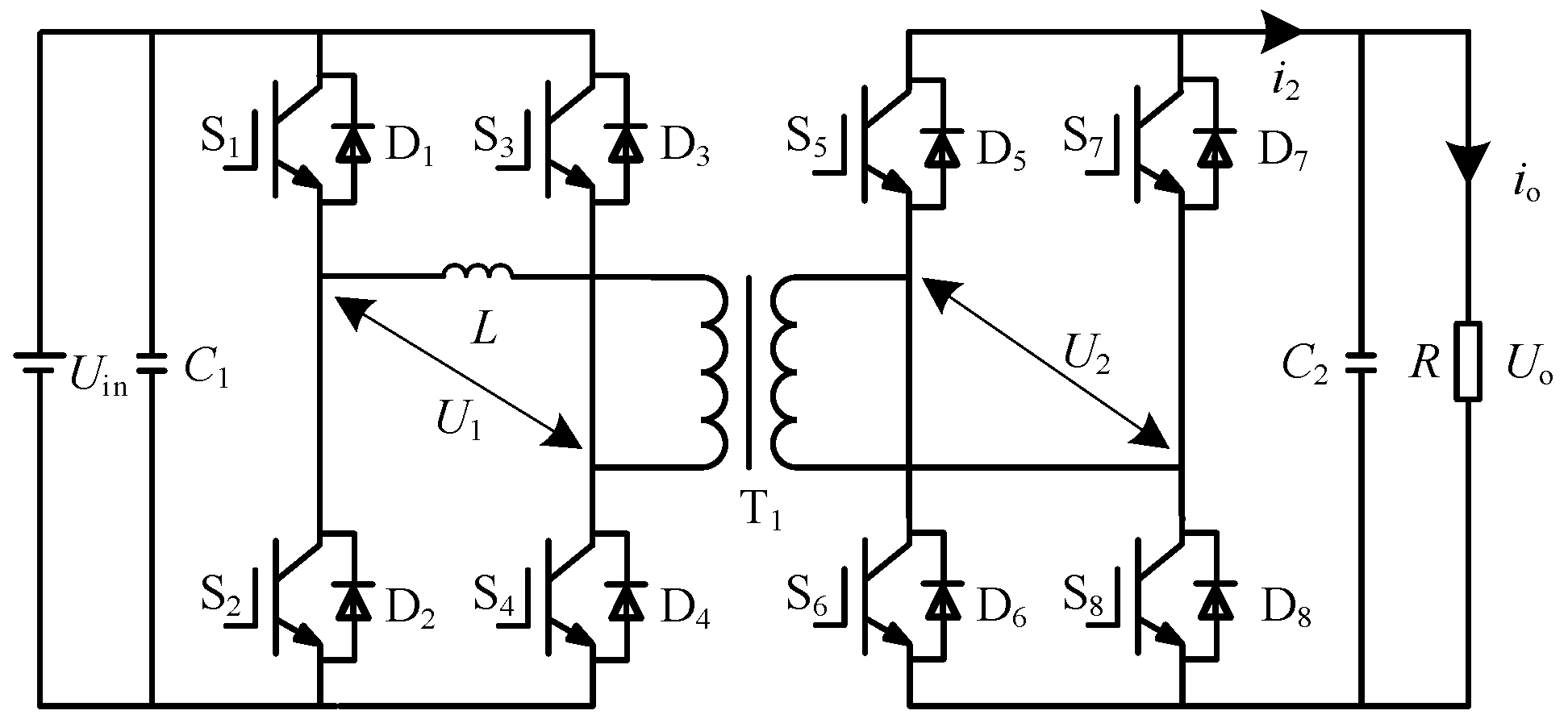
When the DAB converter works normally, the output side capacitance voltage Uo and inductance current IL are selected as state variables. In Figure 2, the differential equation expression of the converter is established according to Kirchhoff’s voltage and current law (2).
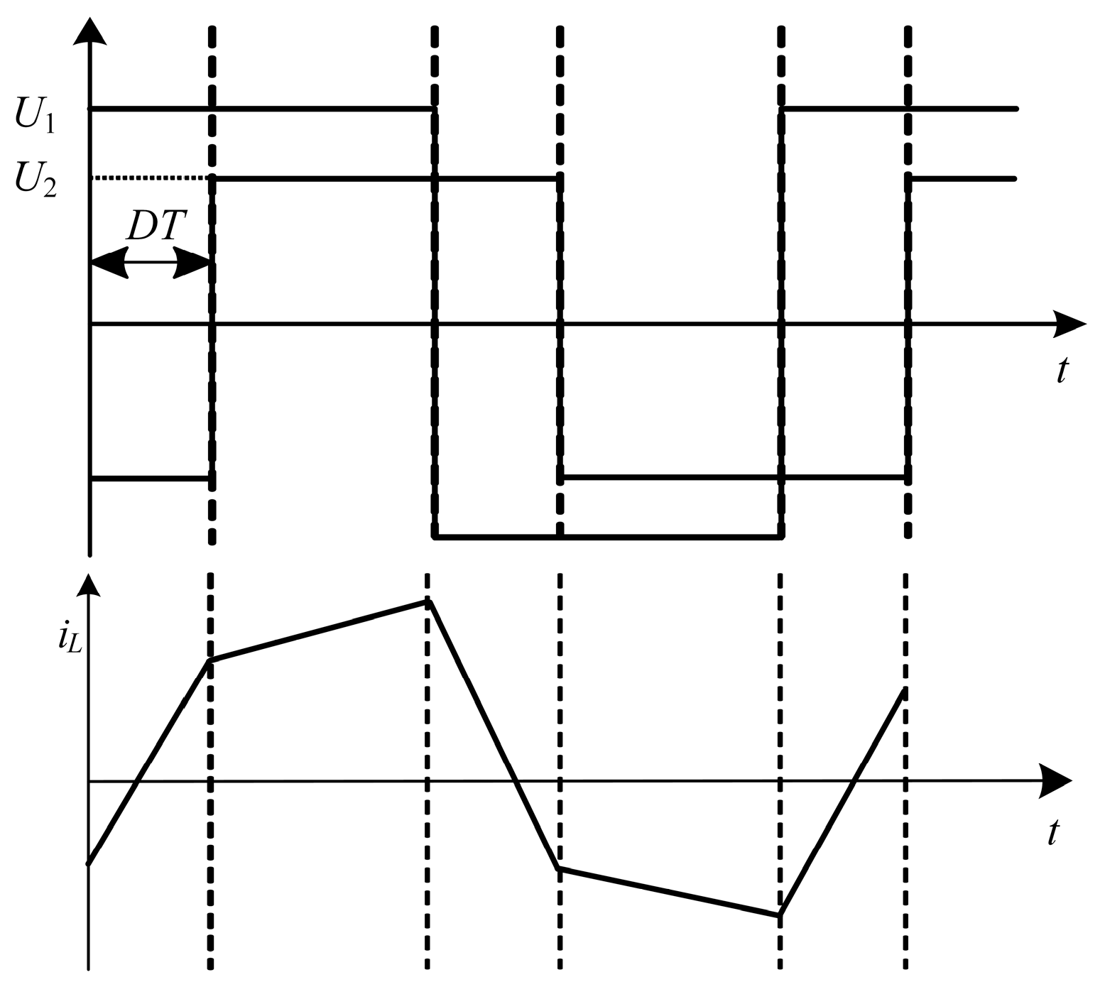
{ C 2 d U o d t = i 2 i o L d i L d t = U 1 N U 2
It can be seen from Figure 3 that the inductance current is a periodic alternating current, and the average value in one switching cycle is 0. In addition, it is known from Equation (1) that after the input and output voltages of the DAB converter are determined, the instantaneous power transmitted is related to the phase shift ratio D and is not affected by the initial time value of the inductance current iL. Therefore, the first equation in Equation (2) is selected to establish the first-order dynamic mathematical model of the DAB converter with the output voltage Uo as the state variable. Equation (2) is written as
i 2 = C 2 d U o d t + i o
In combination with Equation (1), the output current of the converter, io, can be defined by the following expression:
i o = P U o = U o R = N U in 2 f L D ( 1 | D | )
When the DAB converter is subject to external disturbance, the output power quickly tracks the power transmitted by the system at that time, which can improve the dynamic response speed of the converter. The change in the charge and discharge of the output capacitor can reflect the output voltage [12]. Therefore, introducing the current at the output side and selecting the capacitor voltage can shorten the dynamic response time.
The first-order dynamic mathematical model (3) of the converter can be written in the form of the matrix equation
M x + J x + R x = u
where M is a positive definite diagonal matrix, i.e., M = MT; J is the antisymmetric matrix of the internal interconnection structure of the system, i.e., J = −JT; R is the symmetric positive definite matrix of the energy dissipation characteristics of the system, that is, R = RT and R is greater than 0; x is the system state variable vector; and u is the system control input vector, reflecting the exchange of energy between the DAB converter system and the external. The expression of each matrix is as follows:
M = ( 0 0 0 C 2 ) ,   J = ( 0 0 0 0 ) ,   R = ( 0 0 0 1 R ) ,   u = ( 0 i 2 )
Since J is a 0 matrix and an antisymmetric matrix, Equation (5) has the property of the E-L equation.

4. Passive Backstepping Controller for DAB Converter

Passivity-based control controls the physical quantity of the controlled object from the perspective of energy. Passivity is the energy change attribute of the system. The passive controller can only be designed after the passivity and stability of the DAB converter are proven. After the passive controller of the DAB converter is deduced, to accelerate the tracking speed, the passivity-based control and backstepping control are combined to design a passive backstepping composite controller to improve the response speed of the converter system.

4.1. E-L Passivity of DAB Converter

Consider m input and m output systems
{ x = f ( x , u ) y = h ( x ) x ( 0 ) = x 0 R n
where xRn, uRm is the input; yRm is the output, and it is continuous concerning x; and f is the (x, u) local Leibniz.
For the system defined by Equation (6), if there is continuous differentiable semi-positive definite energy storage function H(x) and positive definite function Q(x), for any t > 0, the dissipation inequality
H ( x ( t ) ) H ( x ( 0 ) ) 0 t u T y d τ 0 t Q ( x ) d τ
or
H ( x ) u T y Q ( x )
If the input u, output y and energy supply rate uTy of the system are satisfied, the system is strictly passive.
Equation (7) or Equation (8) describes the increase in the energy of the above system from time 0 to the current time t, which is less than or equal to the total energy injected from the outside, indicating that the operation of the passive system is always accompanied by energy loss.
Let the energy storage function of the DAB converter system by:
H = 1 2 x T M x
In combination with Equation (5), the derivative of the energy storage function H for time
H = x T M x = x T ( u J x R x ) = x T u x T R x
Let the output variable y = u, then
H = x T y x T R x
Integrate both sides of the above formula to obtain:
H ( x ( t ) ) H ( x ( 0 ) ) = 0 t x T y d τ 0 t x T R x d τ
Since R is a positive definite diagonal matrix, xTRx > 0. Thus, there are:
H ( x ( t ) ) H ( x ( 0 ) ) < 0 t x T y d τ
The left side of the inequality (13) is the energy intake of the converter system in this time process, and the right side is the energy externally supplied to the system. The input u and output y of the system and the mapping uy is strictly passive. Consistent with the definition Formula (8), it can be seen that the DAB converter is strictly passive, the passive controller can be designed, and the system is stable.

4.2. Passive Controller Design

The function of the passive controller is to quickly realize xxref, where xref is the expected steady-state value of the DAB converter, and in this paper is the output voltage reference value Uoref = 300 V.
Let the error variable xe = xxref, and the error energy storage function is
H e = 1 2 x e T M x e
For the passive controller of the DAB converter, if He converges to 0 quickly, that is, if He → 0, then xe → 0, the control target can be achieved.
The derivative of the error energy storage function is
H e = x e T M x e
To accelerate 
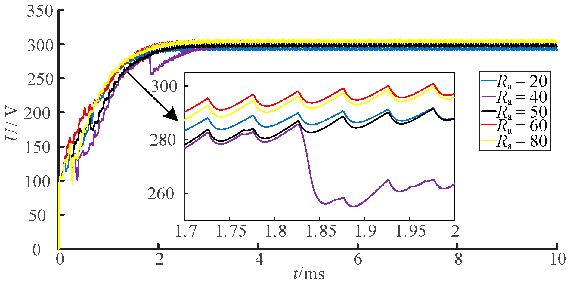
He convergence to 0, damping injection Ra through simulation can improve the response speed of the converter system and improve the energy dissipation speed of the system. From Formula (5):
M x e + R d x e = u M x ref J ( x e + x ref ) R x ref + R a x e
where Rd = R + Ra, positive definite diagonal damping matrix Ra is
R a = ( R a 0 0 1 R a )
By substituting Formula (16) into Formula (15),
H e = x e T [ u M x ref J ( x e + x ref ) R x ref + R a x e ] x e T R d x e
To ensure  H e = x e T R d x e < 0 , the passive controller can be selected as:
u = M x ref + J x + R x ref R a x e
The passive controller Formula (19) can make He → 0 (xe → 0). The speed at which he converges to 0 depends on Rd. If RaR, the speed at which He → 0 depends on the damping matrix Ra, and R has little effect. When the voltage of the primary side of the converter changes suddenly or the resistance of the secondary side switches, the converter is robust to the change in the load R.
Since xref is a given reference value, if there is, the passive controller can be simplified as
u = J x + R x ref R a x e
From Formula (20):
i 2 = U o R R a ( U o U oref )
The passivity-based control equation of the DAB converter of the simultaneous Formula (4) is:
i 2 = N U in 2 f L D ( 1 | D | ) R a ( U o U oref )
When transmitting power in the forward direction,
D = 1 2 1 4 2 f L [ R a ( U o U oref ) + i 2 ] N V in
When power is transmitted in reverse,
D = 1 2 + 1 4 2 f L [ R a ( U o U oref ) + i 2 ] N V in
The control rate of the passive controller with phase shift ratio D is:
{ D = 1 2 1 4 2 f L [ R a ( U o U oref ) + i 2 ] N V in P > 0 D = 1 2 + 1 4 2 f L [ R a ( U o U oref ) + i 2 ] N V in P > 0

4.3. Design of Passive Backstepping Controller

The fast-tracking performance of the output voltage is lost during the design of the DAB converter passive controller [20]. In order to compensate for this deficiency, the dynamic response performance of the converter is improved by introducing backstepping control based on the design of the DAB converter passive controller.
Transform Equation (3) into
x = i 2 i o C 2
where x = Uo.
Let the output voltage error of the converter be:
a = x ref x = U o ref U o
Derive the Formula (27)
a = x ref i 2 i o C 2
In order to realize the converter control target a → 0, the Lyapunov function of a is defined as
V = 1 2 a 2
Derive the upper equation with time in parallel with vertical (14), and the state abnormal reference value will be zero after derivation to obtain the first derivative of Lyapunov.
V = a a = ( i o i 2 ) C 2 a
The linear quantity ka is introduced to improve the dynamic response performance of the converter. Define the value of the control quantity i2
i 2 = i o + C 2 k a
where k is the feedback gain greater than 0. The final backstepping control equation of the DAB converter is
i 2 = i o + C 2 k ( U o ref U o )
Combine vertical (22) and Equation (32) to obtain the passive backstepping control rate of the DAB converter based on the E-L model.
When power is transmitted in the forward direction,
D = 1 2 1 4 2 f L [ k C 2 R a ( U o U oref ) + i o ] N V in
When power is transmitted in reverse,
D = 1 2 + 1 4 2 f L [ k C 2 R a ( U o U oref ) + i o ] N V in
Finally, the phase shift ratio D based on passive backstepping control is
{ D = 1 2 1 4 2 f L [ k C 2 R a ( U o U oref ) + i o ] N V in P > 0 D = 1 2 + 1 4 2 f L [ k C 2 R a ( U o U oref ) + i o ] N V in P < 0
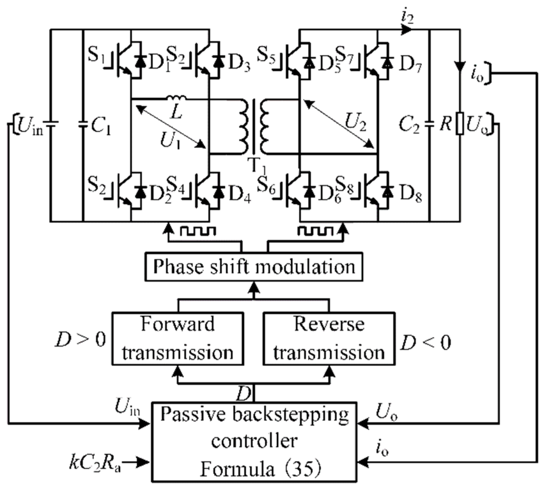
According to the above analysis, the block diagram of the overall control system of the DAB converter based on passivity-based control is shown in Figure 4. Firstly, physical quantities such as the output voltage, current and input voltage of the DAB converter are collected and input to the passive backstepping controller; secondly, the phase shift compared to D of the converter is calculated according to expression (35), and according to the magnitude of the phase shift compared to D, the magnitude and direction of the transmitted power of the DAB converter is determined. Finally, after the phase shift modulation, a square wave is generated to drive the on and off of the switching tubes. When the appropriate injection damping Ra is selected, the output voltage Uo can quickly converge to the reference voltage Uoref.

5. Simulation and Result Analysis

In order to verify the feasibility of the passive backstepping control strategy of the DAB converter, the simulation models of the main circuit and passive backstepping controller of the DAB converter are built in Matlab/Simulink, and the simulation time step is 10−7 s, as shown in Figure 5. The simulation parameters are calculated according to the parameter design in reference [12], as shown in Table 1.

5.1. Selection of Injection Damping for Passivity-Based Control Strategy in This Paper

Passivity-based control establishes a controller based on the physical structure of the system. The goal is to make the whole closed-loop system passive. The method of injection damping is adopted, as described in Section 4.2, to improve the energy dissipation speed of the system and stabilize the system at the reference value. When the passive backstepping controller of the DAB converter selects different values of injection damping, the effect of the output voltage also changes. The output voltage response of different values of injection damping is observed to select the appropriate injection damping. Figure 6 shows the waveforms of the output voltage when the injection damping Ra is 20, 40, 50, 60 and 80 Ω, respectively. It can be seen from the simulation diagram that when the injection damping of the system is 20 Ω, the difference between the output voltage and the reference voltage is about 3.5 V, which does not reach the reference voltage value. As the injection damping increases to 40 Ω, the reference voltage reaches 300 V, but a jitter occurs. When it is increased to 60 and 80 Ω, the response time of the output voltage waveform decreases slightly, the increase is not significant, and it exceeds the reference voltage by 300 V.
Therefore, considering the output voltage response speed and stability of the DAB converter, the injection damping Ra = 50 Ω is selected in this paper.

5.2. Comparison of Different Control Methods under Normal Operation

In order to verify the control performance of the designed passive backstepping controller, the traditional voltage closed-loop control [9] and passivity-based control are selected for comparison. The integral of the time-weighted absolute error (ITAE) index of the error signal is used to optimize the parameters of the PI controller [22] to ensure the optimal PI parameters, and the optimized values are Kp = 0.12 and Ki = 65. Figure 7 shows the comparison waveform of the DAB converter output voltage under the three control methods, and the simulation time is 10 ms. It can be seen that under the traditional PI control, the output voltage overshoots with the given value and reaches stability after 6 ms. The passivity-based control strategy can quickly stabilize the output voltage, reaching the given voltage of 300 V in 3 ms, but the jitter occurs from 1.05 to 1.57 ms. Based on passivity-based control, the passive backstepping control can achieve stability without jitter in 2.65 ms, which can quickly stabilize the output voltage, improve the response speed of the output voltage of the converter and has no overshoot, effectively solving the contradiction between the rapidity and overshoot of the output voltage.

5.3. Comparison of Different Control Methods under Input Voltage Disturbance

When the input terminal of the DAB converter is connected to distributed power sources such as photovoltaic and wind power generation, the input voltage is unbalanced due to the weather, resulting in the voltage fluctuation of the load terminal. Therefore, the converter must ensure the stability of the power supply. To simulate the operation of the DAB converter in response to the fluctuation of input voltage, the following assumptions are made: at 30 ms, the input voltage drops from 750 V to 720 V and rises again to 750 V at 40 ms. The whole simulation time is 50 ms, as shown in Figure 8a.
Figure 8 is a comparison waveform diagram of the output voltage of the converter under three control strategies when the input voltage suddenly drops from 750 V to 720 V and returns to 750 V after 10 ms. As can be seen from Figure 8b, under the traditional PI control, the converter reaches the new state of 287 V after 1.74 ms and then jumps to 297 V after it cannot be stably maintained. During the sudden change, the fluctuation range is large, and the short-term voltage impact is strong. After a little fluctuation, the passive backstepping control reaches a new transmission state, and the output voltage is stable at 289 V. When the input voltage returns to normal, it responds quickly, and it returns to the reference value of 300 V in 1.2 ms. The waveform of the passive backstepping control is similar to that of the passive backstepping control, except that the changed voltage is stable at 277 V, and the total response time is longer. Therefore, it is verified that the passive backstepping control strategy is less affected by the fluctuation of input voltage, stabilizes the fluctuation of distributed energy generation output and reduces the influence of distributed energy on the power quality of the load side.
When designing the control device for a dual active bridge converter, it is not only the dynamic performance of the converter that needs to be taken into account but also the cost of the entire control device, so a comparison of the economics of the three control strategies was carried out. The cost of the whole device of the dual active bridge converter depends mainly on the number of power electronics and high-precision sensors. When using the same topology, the main difference lies in the number of sensors used in the control device [23]; the number used and the comparison of the calculation is shown in Table 2. With the same number of power electronics, the passivity-based control itself is easy to design and reduces the hardware cost of the system compared to traditional PI control. Although the addition of backstepping control increases the amount of computation, the output current waveform is stable, and the reduction in the number of sensors can effectively improve the economy. Taken together, the control strategy in this paper reduces costs while ensuring system reliability.

5.4. The Forward and Reverse Transmission Modes of DAB Converter Are Switched

In the application field of traction power supply systems, facing the frequent braking condition of trains [24], a DAB converter is required to feed back the regenerative braking energy of trains to the port of the energy storage unit, and it can run stably. The waveform of output current under normal operation and input voltage disturbance is shown in Figure 9, and the comparison results of performance indicators are shown in Table 3. The above passive backstepping control strategy is adopted to realize forward and reverse transmission mode switching operation of the DAB converter, and reverse operation recovers braking energy.
To verify the reverse power transmission of the converter, at t = 50 ms, the external trigger signal is changed so that the positive primary and secondary side “charge” is switched to the reverse primary and secondary side “charge”, and the change in “charge” terminal voltage before and after switching is detected. The specific switching is shown in Figure 5 to verify the forward and reverse transmission modes of the DAB converter. Figure 10a shows the forward transmission, in which the primary side transmits power to the secondary side, and the secondary side outputs the voltage waveform. Figure 10b shows the reverse transmission, in which the secondary side transmits power to the primary side, and the primary side outputs the voltage waveform. The simulation results show that the output voltage of the secondary side is 300 V in forward transmission. When the converter is 50 ms, the commutation occurs; that is, the forward and reverse transmission modes are switched, and the “load” terminal voltage of the secondary side changes to 0, at which time the secondary side is switched to “source”. The voltage on the primary side is switched from 0 at the source terminal to “charge”. After the switch, the primary “charge” reaches 750 V at t = 70 ms. At this time, it can quickly reach a stable operation state. Figure 11 shows the change in transmission power at the secondary side of the transformer before and after the switching of the converter. It can be seen that the converter realizes the reverse transmission of power. The simulation results show that the proposed passive backstepping control strategy of the DAB converter can realize the stable switching of power transmission modes. When the converter is connected to an energy storage unit, the regenerative braking energy can be fed back to the original side, thus realizing the flexible scheduling of peak shaving and valley filling of the whole system and power transmission.

6. Conclusions

This paper investigated the dual active bridge converter in the output stage of a modular three-port DC converter to address the problems of slow dynamic response and weak robustness under conventional control. In order to improve the dynamic response of the output voltage of the DAB converter and verify the reverse power transfer of the converter under the passive backstepping control strategy, this paper combined the passivity-based control of the E-L model with backstepping control to the control of the DAB converter, constructed an energy storage function to verify that the converter is strictly passive, and ensured the global stability of the system by injecting damping. The addition of backstepping control eliminates external error and provides good dynamic performance. The feasibility and stability of the passive backstepping control strategy are verified by simulation, and the results show the following:
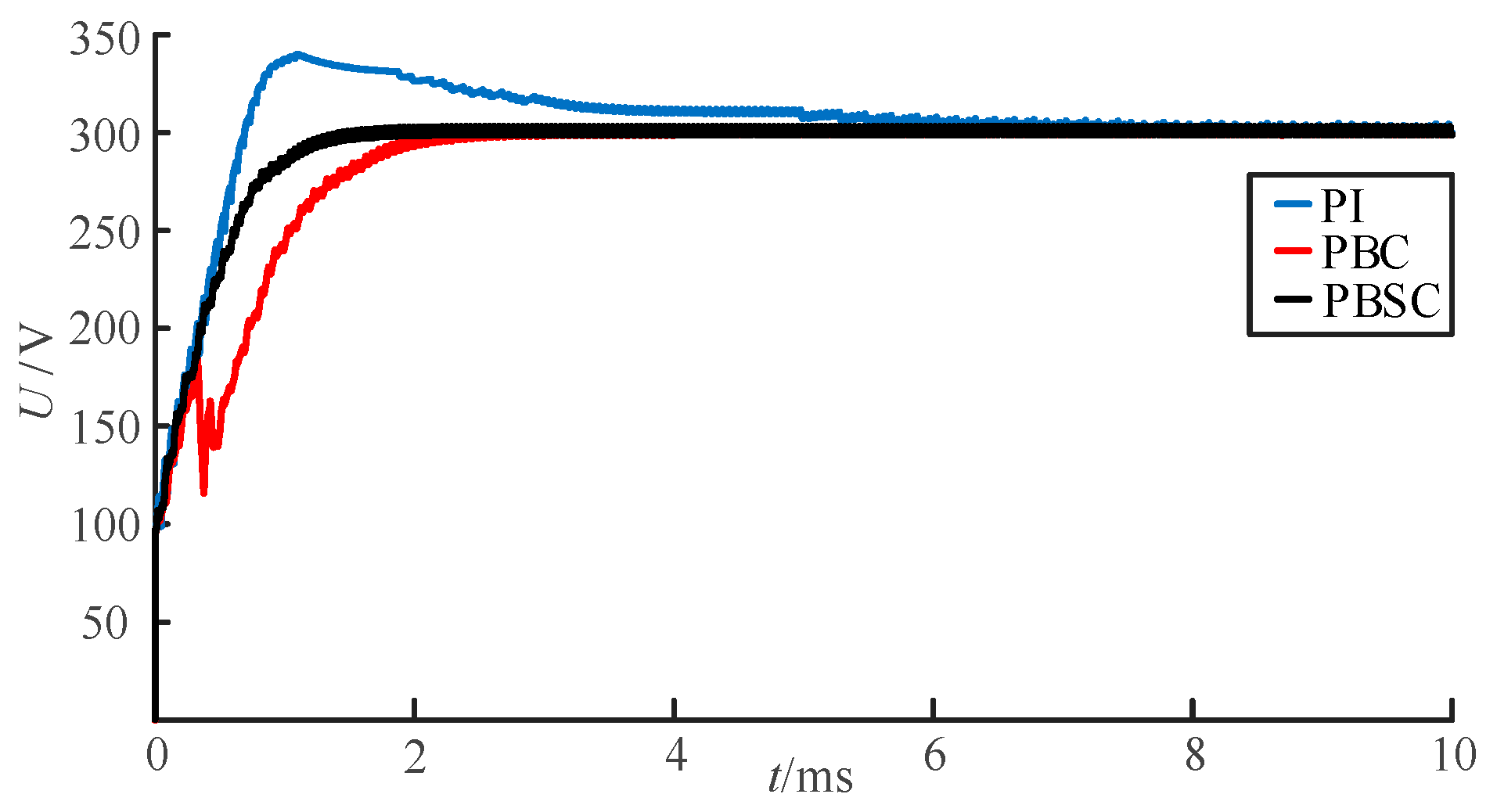
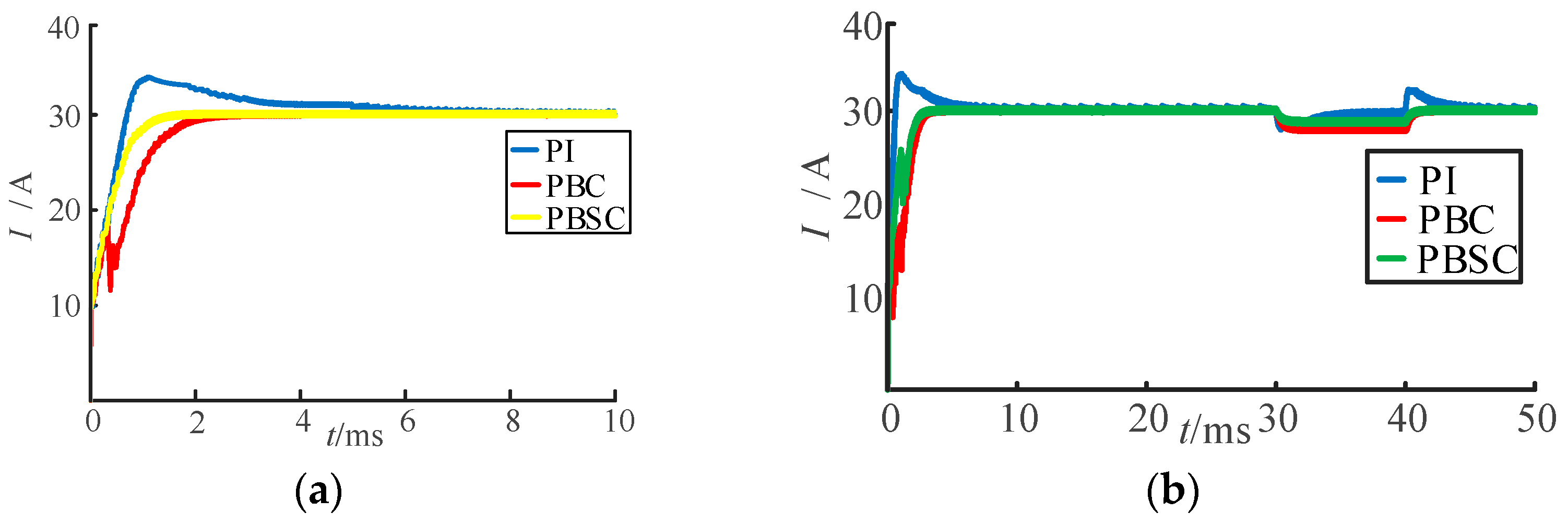
(1) The passive backstepping control strategy is more suitable for this type of nonlinear system of DAB converter than the traditional PI control and passivity-based control monotypic control methods, and the dynamic response is fast, the output voltage reference value is quickly tracked, and the overall control performance is better.
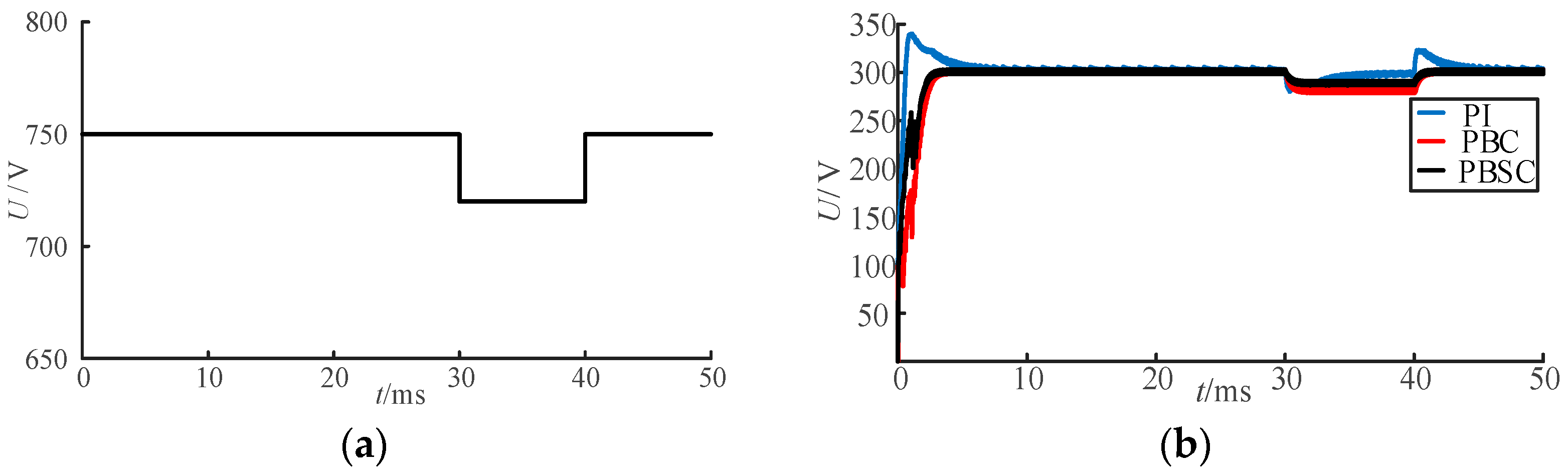
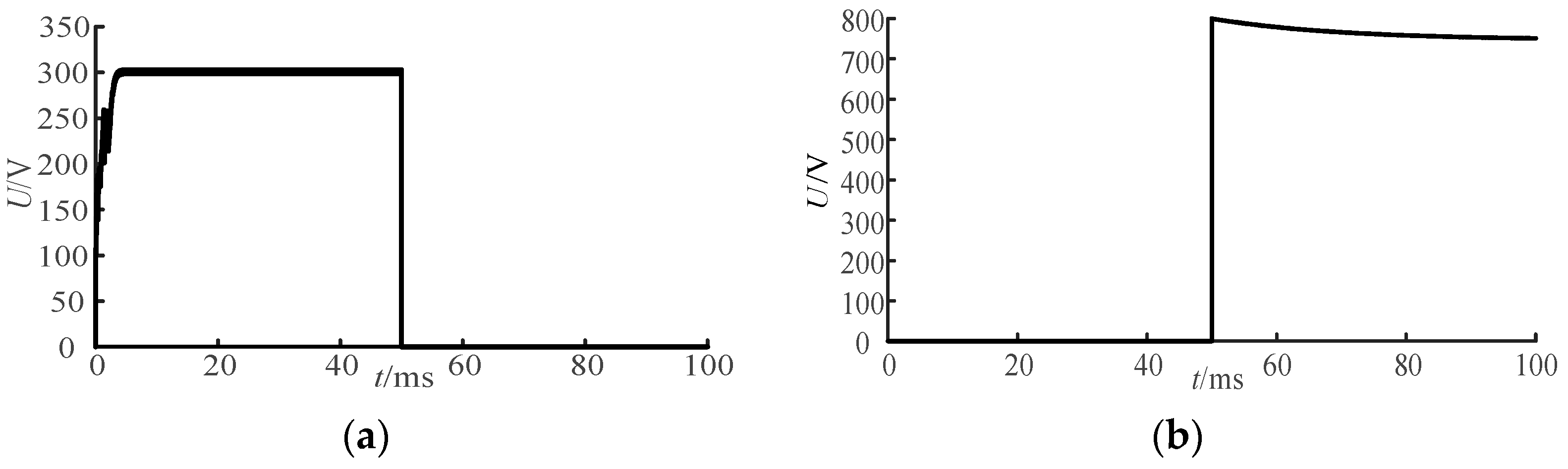
(2) The DAB converter can quickly reach a new operating state and maintain a stable output voltage in the event of sudden changes in the input voltage of distributed power supplies, smoothing out fluctuations in the output power of renewable energy sources such as photovoltaic and wind power generation, and significantly improves the converter’s anti-interference capability.
(3) With the same number of power electronics, the passive backstepping-based control is easy to design and reduces the hardware cost of the system, and the reduction in the number of sensors can effectively improve the economy.
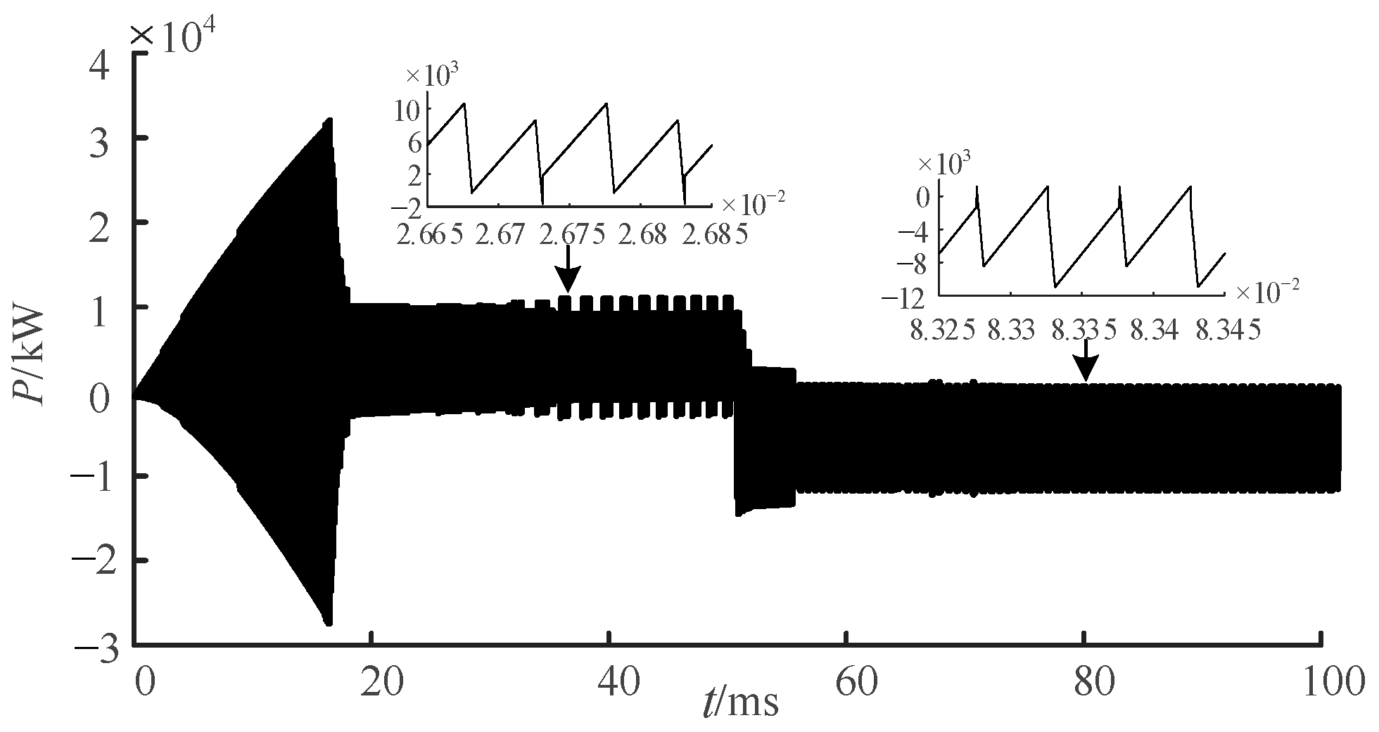
(4) It is verified that the DAB converter is applied to the railway traction power supply system, and the passive backstepping control strategy switches the forward and reverse power transfer modes of the converter to reverse the power transfer and recover the regenerative braking energy on the secondary side, broadening its application scenario.

Author Contributions

Author conceptualization, writing—original draft, formal analysis, and resources, X.F.; review and editing, X.L. All authors have read and agreed to the published version of the manuscript.

Funding

This research was funded by the Science and Technology Plan of Gansu Province and was a key project of the Natural Science Foundation of Gansu Province (Grant No. 22JR5RA317) and Lanzhou Jiaotong University Military civilian Integration Innovation Team Cultivation Fund, China (Grant No. JMTD202209).

Institutional Review Board Statement

Not applicable.

Informed Consent Statement

Not applicable.

Data Availability Statement

The data presented in this study are available in the text.

Conflicts of Interest

The authors declare no conflict of interest.

References

  1. Jiang, H.; Yue, C.; Yan, X.; Hou, J.; Liu, S.; Zhao, T. Influence of system inertia on flexibility resource analysis for an interconnection system with a high proportion of intermittent renewable energy. Power Syst. Prot. Contr. 2021, 49, 44–51. [Google Scholar]
  2. She, X.; Huang, A.; Burgos, R. Review of solid-state transformer technologies and their application in power distribution systems. IEEE J. Emerg. Sel. Top. Power Electron. 2013, 1, 186–198. [Google Scholar] [CrossRef]
  3. Morawiec, M.; Lewicki, A. Power electronic transformer based on cascaded H-bridge converter. Arch. Electr. Eng. 2017, 65, 675–683. [Google Scholar] [CrossRef] [Green Version]
  4. Lu, J.C.; Bai, K.; Taylor, A.R. A modular-designed three-phase high-efficiency high-power-density EV battery charger using dual/triple-phase-shift control. IEEE Trans. Power Electron. 2018, 33, 8091–8100. [Google Scholar] [CrossRef]
  5. Zhao, B.; Yu, Q.; Sun, W. Extended-phase-shift control of isolated bidirectional DC-DC converter for power distribution in microgrid. IEEE Trans. Power Electron. 2012, 27, 4667–4680. [Google Scholar] [CrossRef]
  6. Mohamed, A.; Alexandre, S. Optimal tuning of fractional order controllers for dual active bridge-based DC microgrid including voltage stability assessment. Electronics 2021, 10, 1109. [Google Scholar]
  7. Xia, Y. Cophase power supply system for high-speed railway based on power electronic transformer and its control method. Proc. CSU-EPSA 2019, 31, 98–102. [Google Scholar]
  8. Fei, Y.; Li, R.; Lei, Y.; Shu, Z. Minimize RMS current method of wide input voltage dual active bridge converter. Proc. CSEE 2019, 39, 5656+5693. [Google Scholar]
  9. Demetriades, G.D.; Nee, H.P. Dynamic modeling of the dual-active bridge topology for high-power applications. In Proceedings of the IEEE Power Electronics Specialists Conference, Rhodes, Greece, 15–19 June 2008; pp. 457–464. [Google Scholar]
  10. Oggier, G.; Ordonez, M.; Galvez, J.; Luchino, F. Fast transient boundary control and steady-state operation of the DAB converter using the natural switch-ing surface. IEEE Trans. Power Electron. 2014, 29, 946–957. [Google Scholar] [CrossRef]
  11. Vazquez, N.; Liserre, M. Peak current control and feed-forward compensation of a DAB converter. IEEE Trans. Ind. Electron. 2020, 67, 8381–8391. [Google Scholar] [CrossRef]
  12. Kan, J.; Wu, Y.; Xie, S.; Tang, Y.; Xue, Y.; Yao, Z.; Zhang, B. Dual-Active-Bridge bidirectional DC/DC converter based on high-frequency AC buck-boost theory. Proc. CSEE 2017, 37, 1797–1808. [Google Scholar]
  13. Jeung, Y.C.; Lee, D.C. Voltage and current regulations of bidirectional isolated dual-active-bridge DC-DC converters based on a double-integral sliding mode control. IEEE Trans. Power Electron. 2019, 34, 6937–6946. [Google Scholar] [CrossRef]
  14. Zhang, H.; Li, Y.; Li, Z.; Zhao, C.; Gao, F.; Xu, F.; Wang, P. Model predictive control strategy of DC transformer based on extended state observer. Electr. Power Aut. Eq. 2021, 41, 104–110. [Google Scholar]
  15. Jafari, M.; Malekjamshidi, Z.; Zhu, J.G.; Khooban, M.H. Novel predictive fuzzy logic-based energy management system for grid-connected and off-grid operation of residential smart microgrids. IEEE J. Emerg. Sel. Top. Power Electron. 2020, 8, 1391–1404. [Google Scholar] [CrossRef]
  16. Askarian, I.; Bagawade, S.; Pahlevani, M.; Knight, A.; Bakhshai, A. Robust digital nonlinear control system for dual active bridge (DAB) DC/DC converters with asym-metric half-cycle modulation. IEEE J. Emerg. Sel. Top. Ind. Electron. 2020, 1, 123–132. [Google Scholar] [CrossRef]
  17. An, F.; Song, W.; Yang, K. Model predictive control and power balance scheme of dual-active-bridge DC-DC converters in power electronic transformer. Proc. CSEE. 2018, 38, 3921–3929+4034. [Google Scholar]
  18. Cheng, Q.; Wei, L.; Cheng, Y.; Shen, L.; Wang, Y. Permanent magnet synchronous motor passivity-based control drive system based on quasi-Z source matrix converter. Proc. CSEE 2019, 39, 6746–6756. [Google Scholar]
  19. Cheng, Q.; Jiang, C.; Shen, L.; Cheng, Y. Passivity-Based control strategy of quasi Z-source three-level grid-connected inverter. Trans. CHN Electr-Techn. Soc. 2020, 35, 4361–4372. [Google Scholar]
  20. Chen, Y.; Yang, L.; Wang, P. Backstepping control strategy for interlinking converters in low-voltage hybrid AC/DC microgrid based on disturbance observer. High Volt. Eng. 2022, 48, 4082–4092. [Google Scholar]
  21. Xue, H.; Pan, Z.; Wang, Y.; Tian, G.; Yang, X. MMC passivity-based and backstepping circulating current suppressing method based on port-controlled hamiltonian with dissipation model. Trans. CHN Electr-Techn. Soc. 2020, 35, 2596–2611. [Google Scholar]
  22. Zhang, S. Drive and Control Technology of Magnetic Levitation Planar Motor; Science Press: Beijing, China, 2015; pp. 178–180. [Google Scholar]
  23. Chen, X.; Zhou, N.; Han, X.; Li, Y.; Li, B.; Li, B. A hybrid DC circuit breaker with adaptive reclosing ability. Power Syst. Tech. 2022, 46, 4718–4731. [Google Scholar]
  24. Liu, H.; Geng, A.; He, Z.; Hu, H.; Zhang, H. Research on energy utilization scheme of regenerative braking for heavy haul railway. J. Electr. Eng. 2021, 16, 157–165. [Google Scholar]
Figure 1. Modular three-port DC converter structure.
Electronics 12 01074 g001
Figure 2. Structure of dual active bridge converter.
Electronics 12 01074 g002
Figure 3. Voltage and current waveform diagram of single phase shift control.
Electronics 12 01074 g003
Figure 4. Block diagram of passive backstepping control strategy for DAB converter.
Electronics 12 01074 g004
Figure 5. Simulation model of DAB converter.
Electronics 12 01074 g005
Figure 6. Output voltage at different damping injections.
Electronics 12 01074 g006
Figure 7. Output voltage waveform comparison.
Electronics 12 01074 g007
Figure 8. Output voltage waveforms of different control methods when the input voltage drops suddenly: (a) input voltage; (b) output voltage.
Electronics 12 01074 g008
Figure 9. Output current waveform comparison: (a) in normal working mode; (b) input voltage disturbance operating mode.
Electronics 12 01074 g009
Figure 10. Switch from forward transmission mode to reverse transmission mode: (a) secondary output voltage; (b) primary input voltage.
Electronics 12 01074 g010
Figure 11. Simulation waveform of transmission mode switching power change.
Electronics 12 01074 g011
Table 1. DAB converter simulation parameters.
ParameterValue
Input voltage Uin750/720 V
Input capacitance C1100 µF
Equivalent inductance L10 µH
Transformation ratio N750:300
Switching frequency f20 kHz
Output capacitance C2100 µF
Injection damping Ra50 Ω
Reaction coefficient k1600
Load resistance R10 Ω
Output voltage Uo300 V
Table 2. Comparison of the number of devices and calculation accuracy under the three DAB control strategies.
Control PolicyIGBT QuantityNumber of SensorsCalculation Accuracy
Traditional PI control85high
Passivity-based control83high
Passive backstepping control83higher
Table 3. Comparison of current performance indexes under three DAB control strategies.
Control PolicyResponse Time under Normal Operation t/msResponse Time to Reach a New State under Sudden Voltage Change t/msCurrent Stability Value in New State/ATotal Response Time under Sudden Voltage Change t/ms
Traditional PI control631.74/3828.7/29.747.25
Passivity-based control331.427.741.5
Passive backstepping control2.6531.128.941.2
Disclaimer/Publisher’s Note: The statements, opinions and data contained in all publications are solely those of the individual author(s) and contributor(s) and not of MDPI and/or the editor(s). MDPI and/or the editor(s) disclaim responsibility for any injury to people or property resulting from any ideas, methods, instructions or products referred to in the content.

