

Design of Tight Coupling Antenna to Realize Ultra-Wideband Function

 and
and 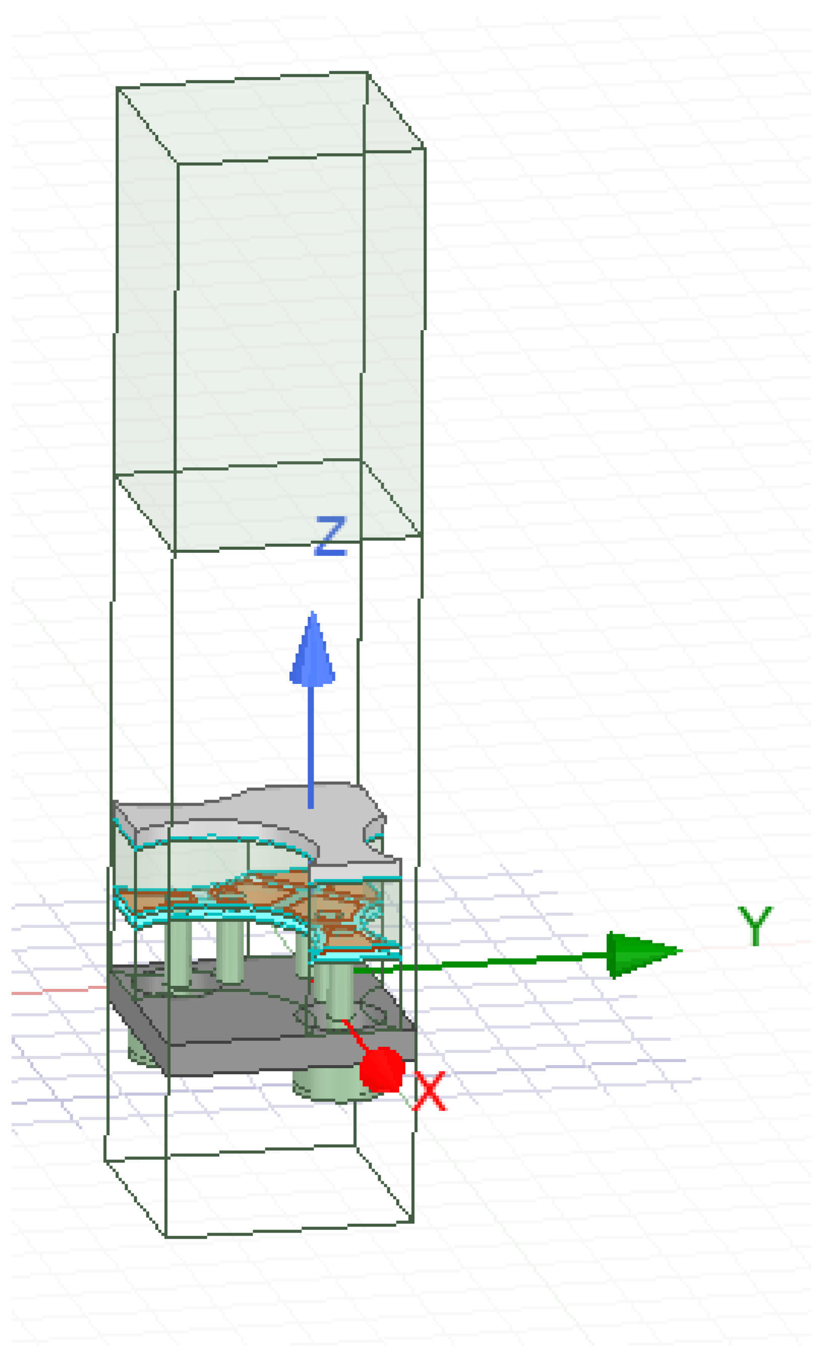
Abstract
:1. Introduction
- According to the tightly coupled antenna theory, a dual-polarized tightly coupled antenna of 15–40 GHz is designed. The designed antenna can achieve ultra-wideband performance.
- The antenna size is 3.75 mm × 3.75 mm × 2.38 mm, and the spacing between the elements is 3.75 mm. The media used from bottom to top are Rogers5880, PP adhesive, RogersTMM10, and feed line using coaxial line directly, with a coaxial line inner core radius of 0.2 mm.
2. Principle of Tight Coupling
3. Design of Tightly Coupled Antenna
4. Test and Simulations
4.1. Standing Wave Test
- (1)
- Connect the device under test and the test instrument according to Figure 6;
- (2)
- Start the test instrument and preheat it for 30 min;
- (3)
- Set the center frequency of the vector network analyzer to 33 GHz and the frequency range to 26.5–40 GHz, and test 401 frequency points. The level is set to 20 dBm, port 1 is connected to the receiving array element, port 2 is connected to other array elements in turn, and the unconnected array element is connected to the load;
- (4)
- The amplitude and phase of S11 and S21 parameters are stored, and the active S parameter matrix is synthesized to obtain the standing wave of the antenna unit to be measured.

4.2. Pattern Test
- (1)
- Connect broadband horn antenna and standard horn antenna AVTAH320;
- (2)
- Start the test instrument and preheat it for 30 min;
- (3)
- Set the center frequency of the vector network analyzer to 33 GHz, frequency range to 26.5–40 GHz, level to −5 dBm, port 1 to connect the broadband horn antenna as transmitting antenna, port 2 to join the standard horn antenna AVTAH320 as receiving antenna, adjust the turntable and set the azimuth axis (theta) to −5°~+5°. Test and save S21 amplitude and phase values (horizontal/vertical polarization direction);
- (4)
- Take off the standard horn antenna and replace it with a Ka patch array antenna. The azimuth axis (theta) is selected from −100° to +100°, and each element’s amplitude and phase values of S21 (horizontal/vertical polarization direction) are tested and saved;
- (5)
- The gain values of each array of Ka patch array antenna are calculated as shown in (1), where represents the gain of each array of Ka patch array antenna, represents the gain of standard horn antenna, and , respectively, represent the received power levels of each array of Ka patch array antenna and standard antenna.
5. Conclusions
Author Contributions
Funding
Data Availability Statement
Conflicts of Interest
References
- Nadeem, I.; Alibakhshikenari, M.; Babaeian, F.; Althuwayb, A.A.; Virdee, B.S.; Azpilicueta, L.; Khan, S.; Huynen, I.; Falcone, F.; Denidni, T.; et al. A comprehensive survey on ‘circular polarized antennas’ for existing and emerging wireless communication technologies. J. Phys. D Appl. Phys. 2022, 55, 033002. [Google Scholar] [CrossRef]
- Wyk, M.; Ping, L.; Chen, G. Multivaluedness in Networks: Shannon’s Noisy-Channel Coding Theorem. IEEE Trans. Circuits Syst. II. Express Briefs 2021, 68, 3234–3235. [Google Scholar]
- Lee, H.; Chun, J. Virtual Array Response Vector for Angle Estimation of MIMO Radar with a Wide-Band Interleaved OFDM Signal. IEEE Commun. Lett. 2021, 25, 1539–1543. [Google Scholar] [CrossRef]
- Liu, Y.; Wang, C.; Zheng, G.; Gong, J. An Active Anti-Jamming Approach for Frequency Diverse Array Radar with Adaptive Weights. J. Beijing Inst. Technol. 2021, 30, 403–411. [Google Scholar]
- Logan, J.T.; Kindt, R.W.; Vouvakis, M.N. Low Cross-Polarization Vivaldi Arrays. IEEE Trans. Antennas Propag. 2018, 66, 1827–1837. [Google Scholar] [CrossRef] [Green Version]
- Novak, M.H.; Volakis, J.L. Ultrawideband antennas for multiband satellite communications at UHF–Ku frequencies. IEEE Trans. Antennas Propag. 2015, 63, 1334–1341. [Google Scholar] [CrossRef]
- Han, L.; Wang, G.; Zhang, L.; Jiang, W.; Zhao, P.; Tang, W.; Dang, T.; Zheng, H. Tightly Coupled Ultra-Wideband Phased-Array Implemented by Three-Dimensional Inkjet Printing Technique. Electronics 2022, 11, 3320. [Google Scholar] [CrossRef]
- Zhou, Y.; Zhu, F.; Gao, S.; Luo, Q.; Wen, L.H.; Wang, Q.; Yang, X.; Geng, Y.; Cheng, Z. Tightly Coupled Array Antennas for Ultra-Wideband Wireless Systems. IEEE Access 2018, 6, 61851–61866. [Google Scholar] [CrossRef]
- Jiang, W.; Gong, S.X.; Cui, S. An ultra-wideband monopole antenna with water-wave structure. Microw. Opt. Technol. Lett. 2011, 53, 1700–1703. [Google Scholar] [CrossRef]
- Zhang, L.; Gao, S.; Luo, Q.; Young, P.R.; Li, Q.; Geng, Y.L.; Abd-Alhameed, R.A. Single-Feed Ultra-Wideband Circularly Polarized Antenna With Enhanced Front-to-Back Ratio. IEEE Trans. Antennas Propag. 2015, 64, 355–360. [Google Scholar] [CrossRef] [Green Version]
- Sghaier, N. Design and analysis of wideband MIMO antenna arrays for 5G smartphone application. Int. J. Microw. Wirel. Technol. 2021, 14, 511–523. [Google Scholar] [CrossRef]
- Balani, W.; Sarvagya, M.; Samasgikar, A.; Ali, T.; Kumar, P. Design and Analysis of Super Wideband Antenna for Microwave Applications. Sensors 2021, 21, 477. [Google Scholar] [CrossRef] [PubMed]
- Addepalli, T.; Anitha, V.R. Design and analysis of a novel compact spanner-shaped ultra-wideband antenna for MIMO systems. Int. J. Commun. Syst. 2021, 34, e4739. [Google Scholar] [CrossRef]
- Goudarzi, M. Design of a wideband single-layer partially reflective surface for a circularly-polarized resonant cavity antenna. AEU Arch. Fur Elektron. Und Ubertragungstechnik Electron. Commun. 2021, 129, 153535. [Google Scholar] [CrossRef]
- Zhang, H.; Yang, S.; Xiao, S.W.; Chen, Y.; Qu, S.W.; Hu, J. Ultrawideband Phased Antenna Arrays Based on Tightly Coupled Open Folded Dipoles. IEEE Antennas Wirel. Propag. Lett. 2019, 18, 378–382. [Google Scholar] [CrossRef]
- Zhou, W.; Chen, Y.; Yang, S. Dual-Polarized Tightly Coupled Dipole Array for UHF–X-Band Satellite Applications. IEEE Antennas Wirel. Propag. Lett. 2019, 18, 467–471. [Google Scholar] [CrossRef]
- Wang, B.; Yang, S.; Chen, Y.; Qu, S.; Hu, J. Low Cross-Polarization Ultra-Wideband Tightly Coupled Balanced Antipodal Dipole Array. IEEE Trans. Antennas Propag. 2020, 68, 4479–4488. [Google Scholar] [CrossRef]
- Zhang, Z.; Huang, M.; Chen, Y.; Qu, S.W.; Hu, J.; Yang, S. In-Band Scattering Control of Ultra-Wideband Tightly Coupled Dipole Arrays Based on Polarization Selective Metamaterial Absorber. IEEE Trans. Antennas Propag. 2020, 68, 7927–7936. [Google Scholar] [CrossRef]


Disclaimer/Publisher’s Note: The statements, opinions and data contained in all publications are solely those of the individual author(s) and contributor(s) and not of MDPI and/or the editor(s). MDPI and/or the editor(s) disclaim responsibility for any injury to people or property resulting from any ideas, methods, instructions or products referred to in the content. |
© 2023 by the authors. Licensee MDPI, Basel, Switzerland. This article is an open access article distributed under the terms and conditions of the Creative Commons Attribution (CC BY) license (https://creativecommons.org/licenses/by/4.0/).
Share and Cite
Wang, K.; Xu, Z.; Hao, C.; Deng, Y.; Wang, Y.; Xu, K.; Xu, H. Design of Tight Coupling Antenna to Realize Ultra-Wideband Function. Electronics 2023, 12, 988. https://doi.org/10.3390/electronics12040988
Wang K, Xu Z, Hao C, Deng Y, Wang Y, Xu K, Xu H. Design of Tight Coupling Antenna to Realize Ultra-Wideband Function. Electronics. 2023; 12(4):988. https://doi.org/10.3390/electronics12040988
Chicago/Turabian StyleWang, Kunye, Zheng Xu, Chengxiang Hao, Yunkai Deng, Yi Wang, Kaiming Xu, and Haitao Xu. 2023. "Design of Tight Coupling Antenna to Realize Ultra-Wideband Function" Electronics 12, no. 4: 988. https://doi.org/10.3390/electronics12040988