

Virtual Training System for the Teaching-Learning Process in the Area of Industrial Robotics

Abstract
:1. Introduction
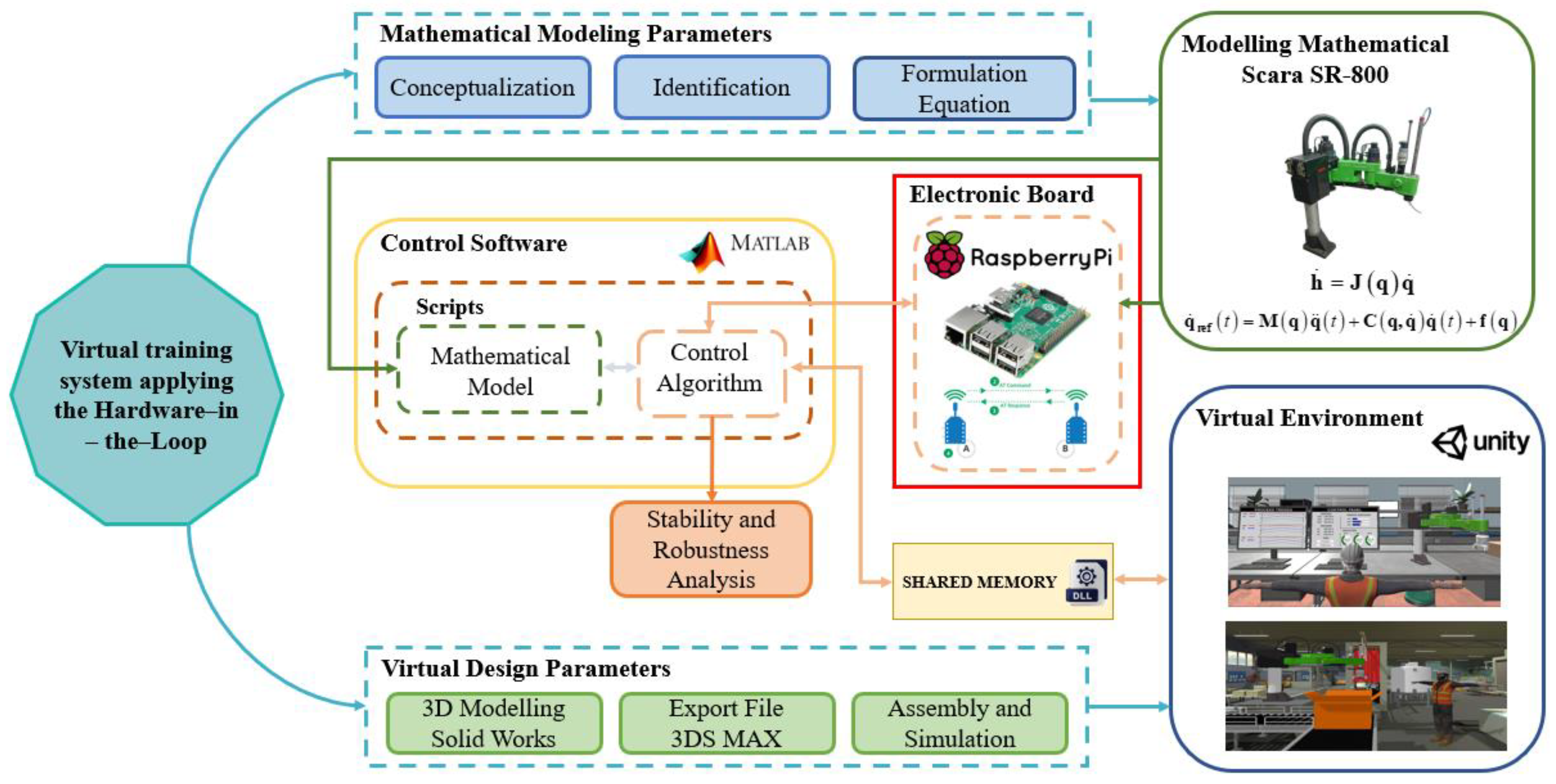
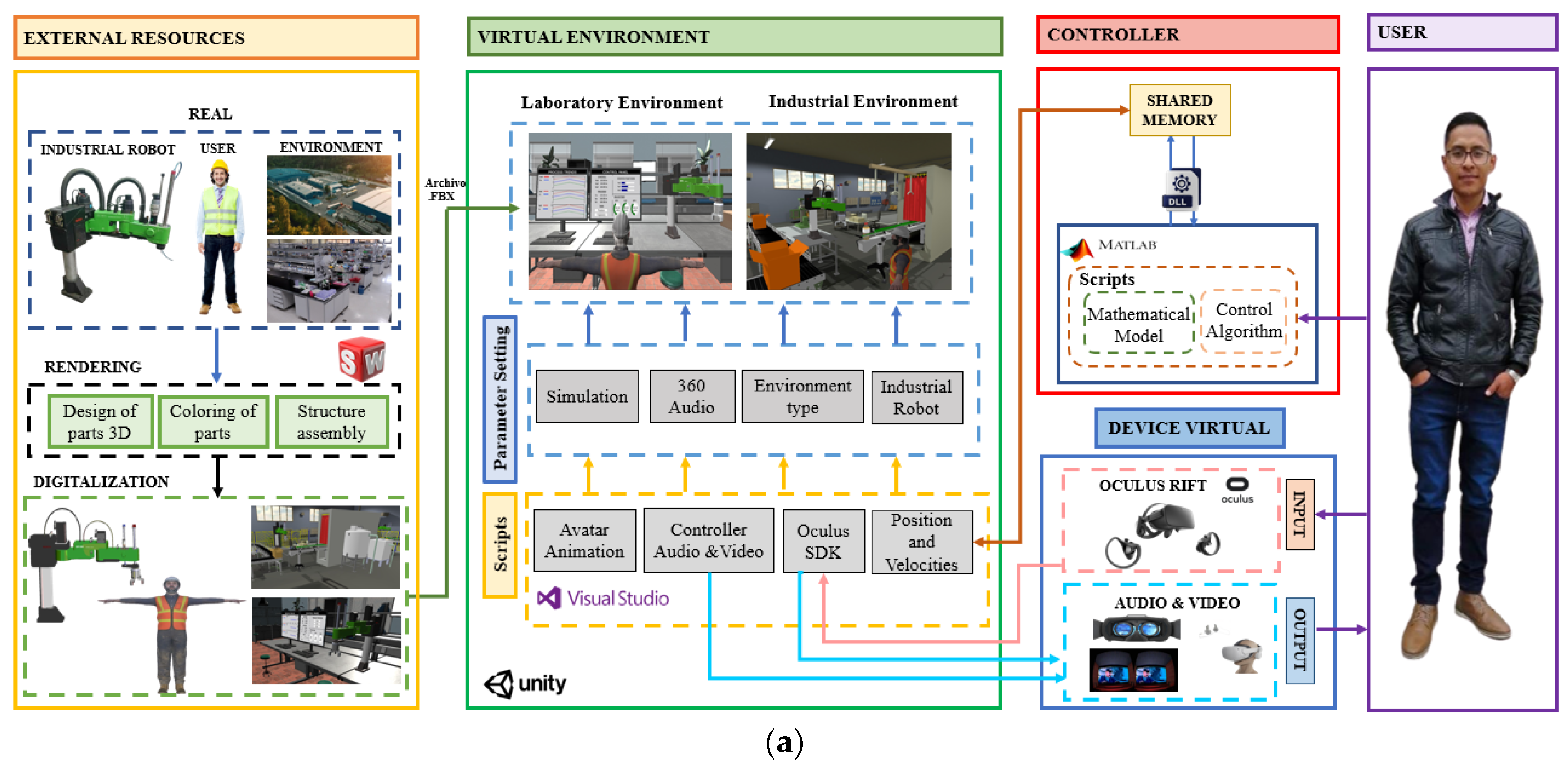
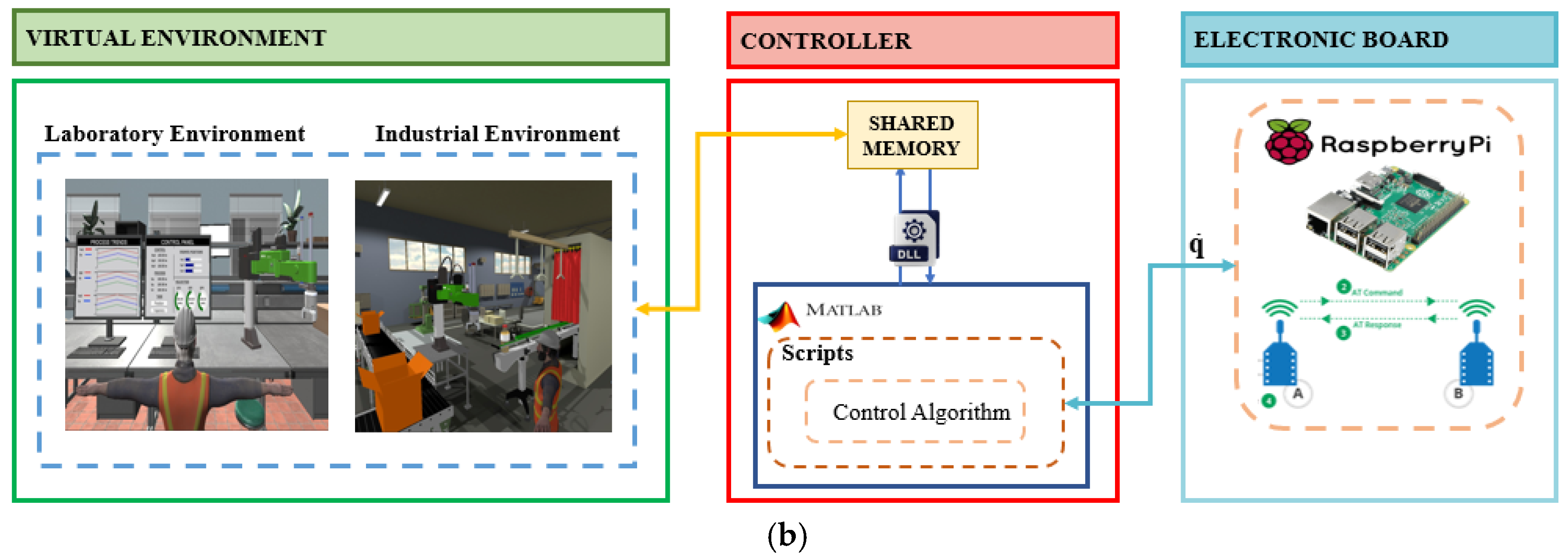
2. Methodology
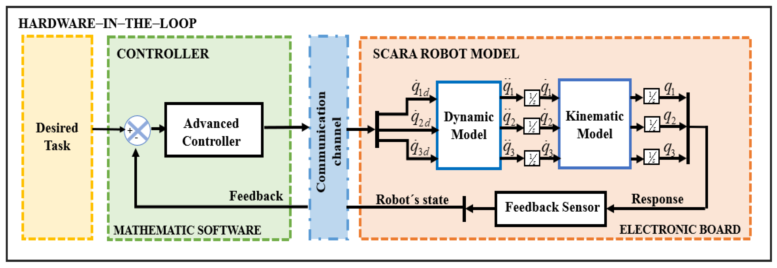
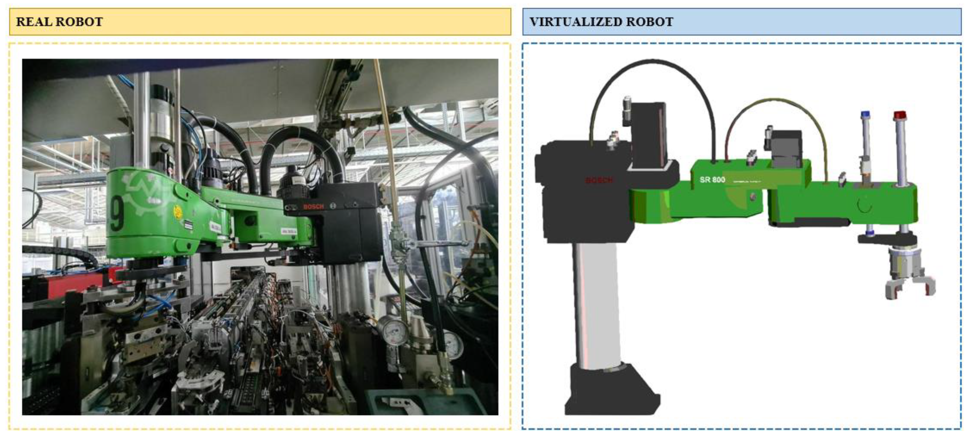
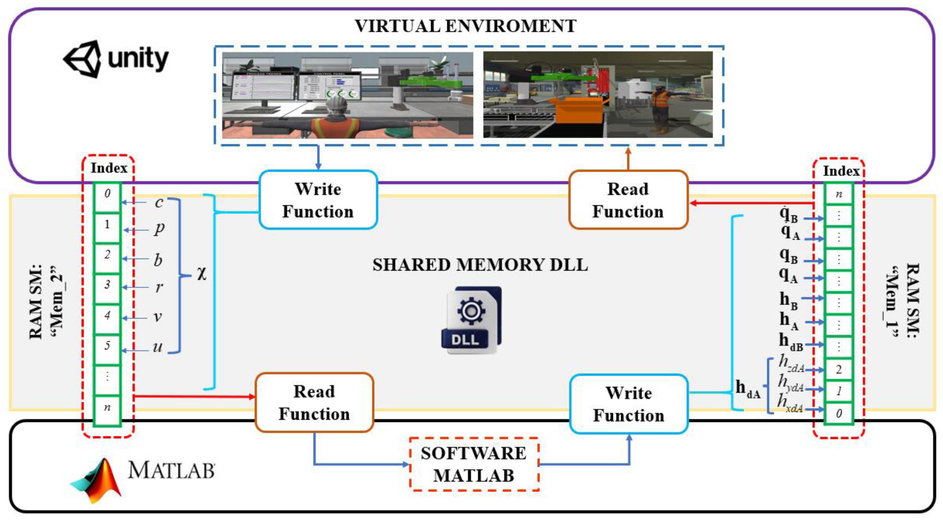
3. Virtualization–Full Simulation–HIL
4. Modeling
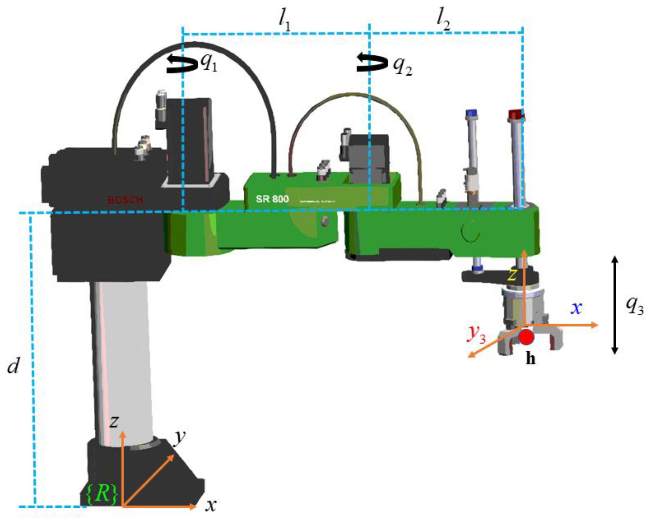
4.1. Kinematics of the Robot Manipulator Scara Bosh
4.2. Dynamic Model of the Scara Manipulator Robot
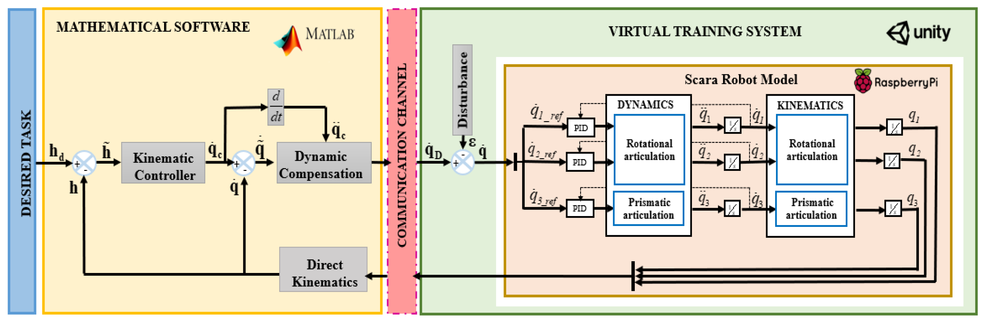
5. Control Scheme
5.1. Kinematic Control
Stability Analysis
5.2. Dynamic Compensation Controller
5.2.1. Stability Analysis
5.2.2. Robustness Analysis
6. Analysis and Results
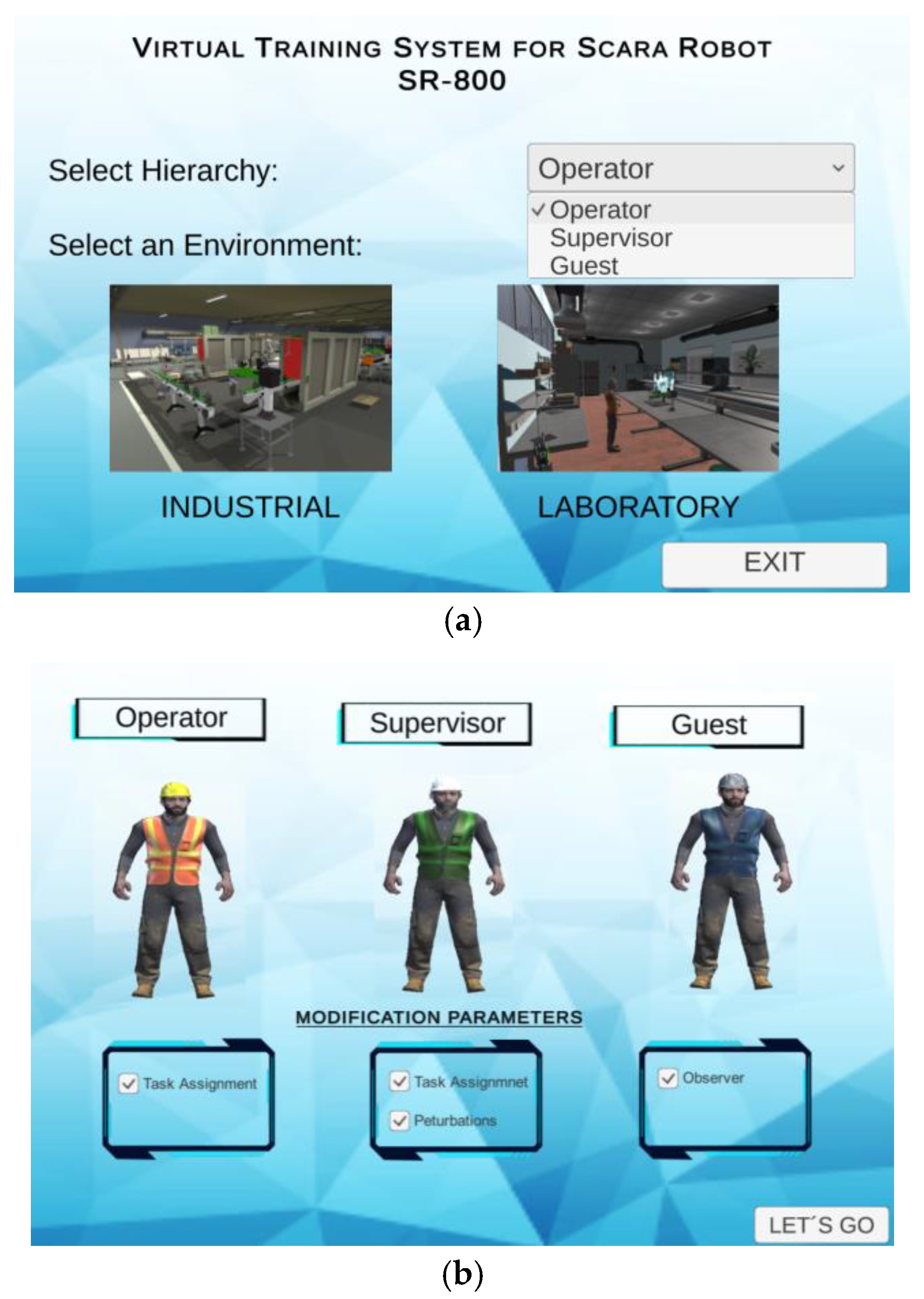
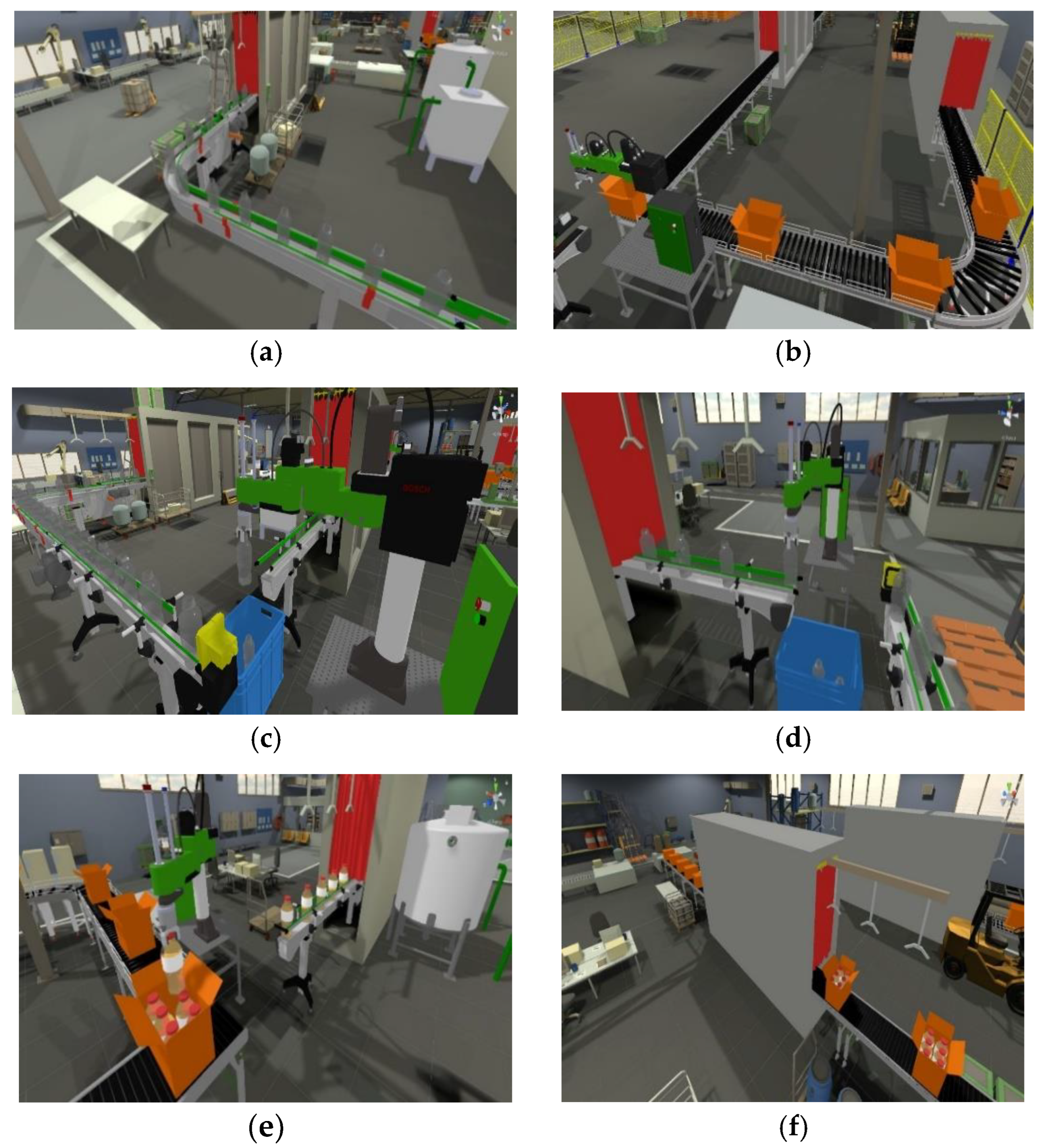
6.1. Operability Interface
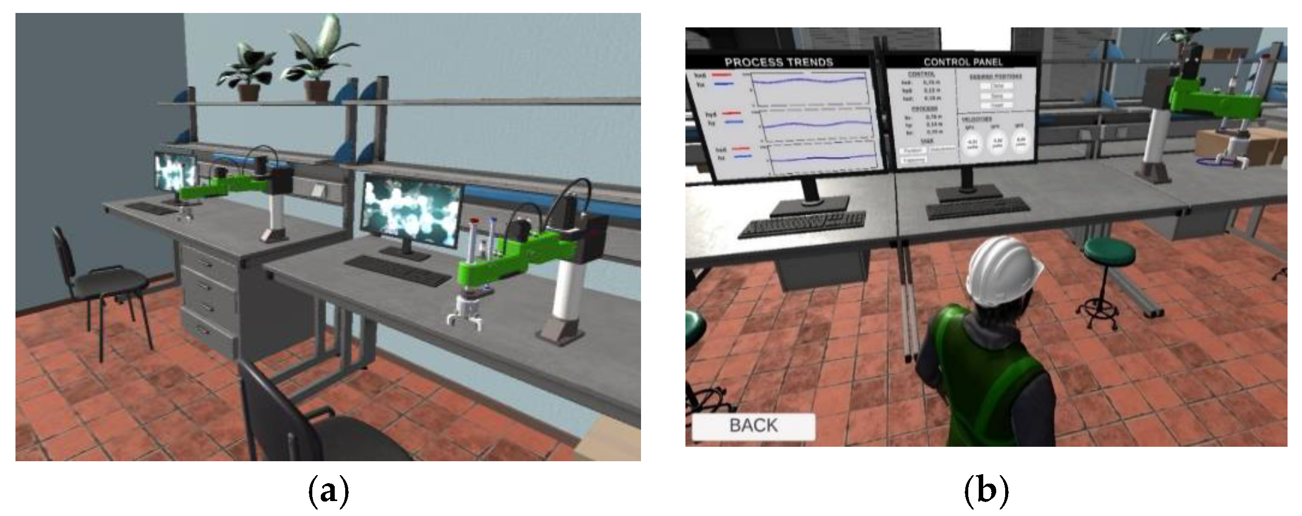
6.2. Laboratory Environment
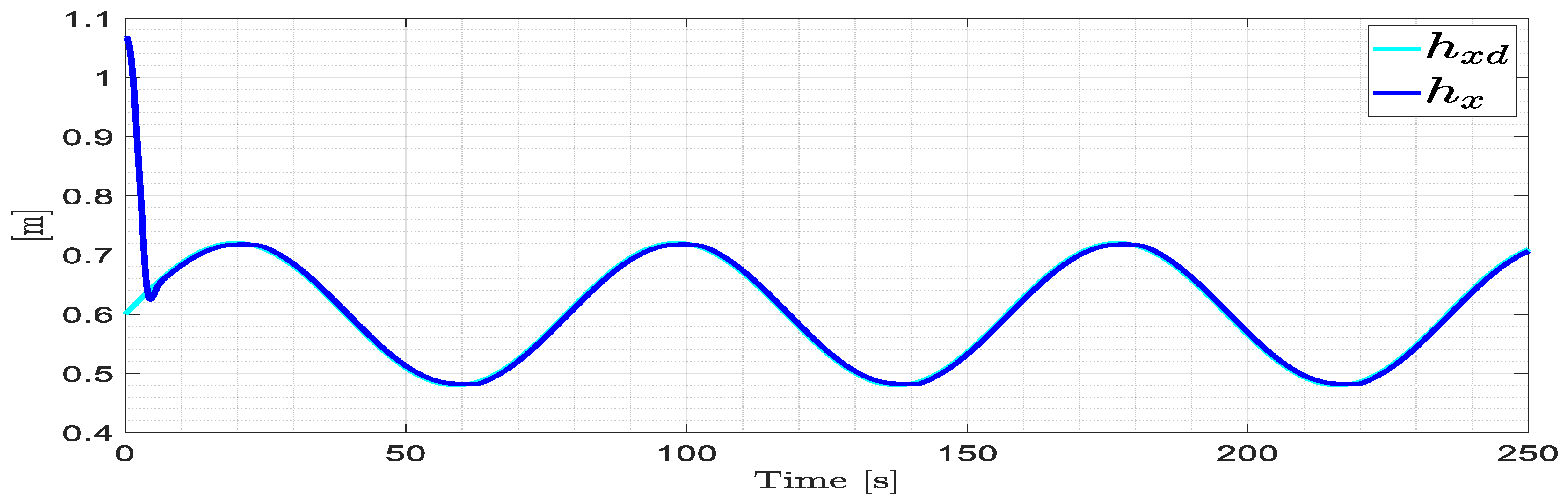
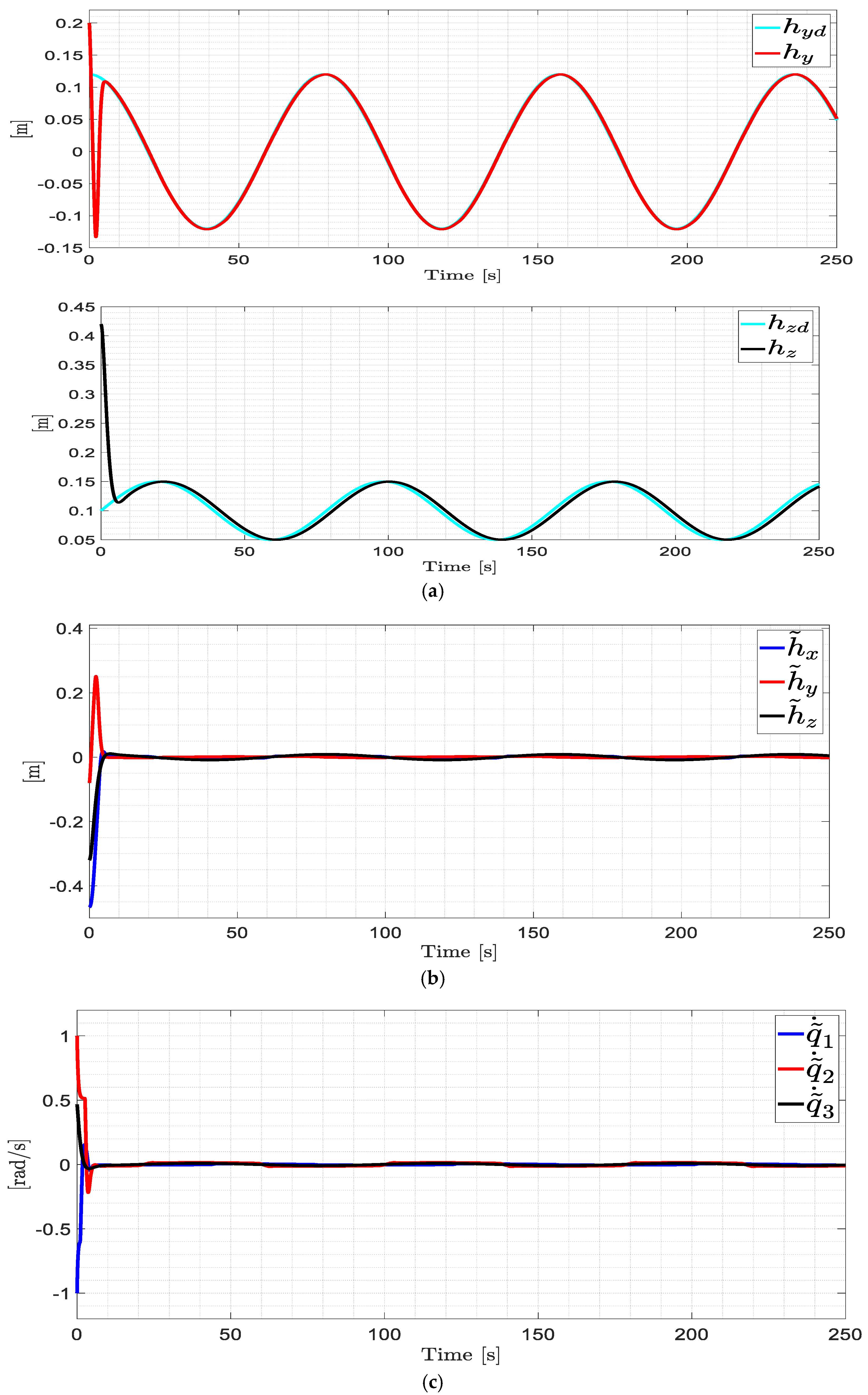
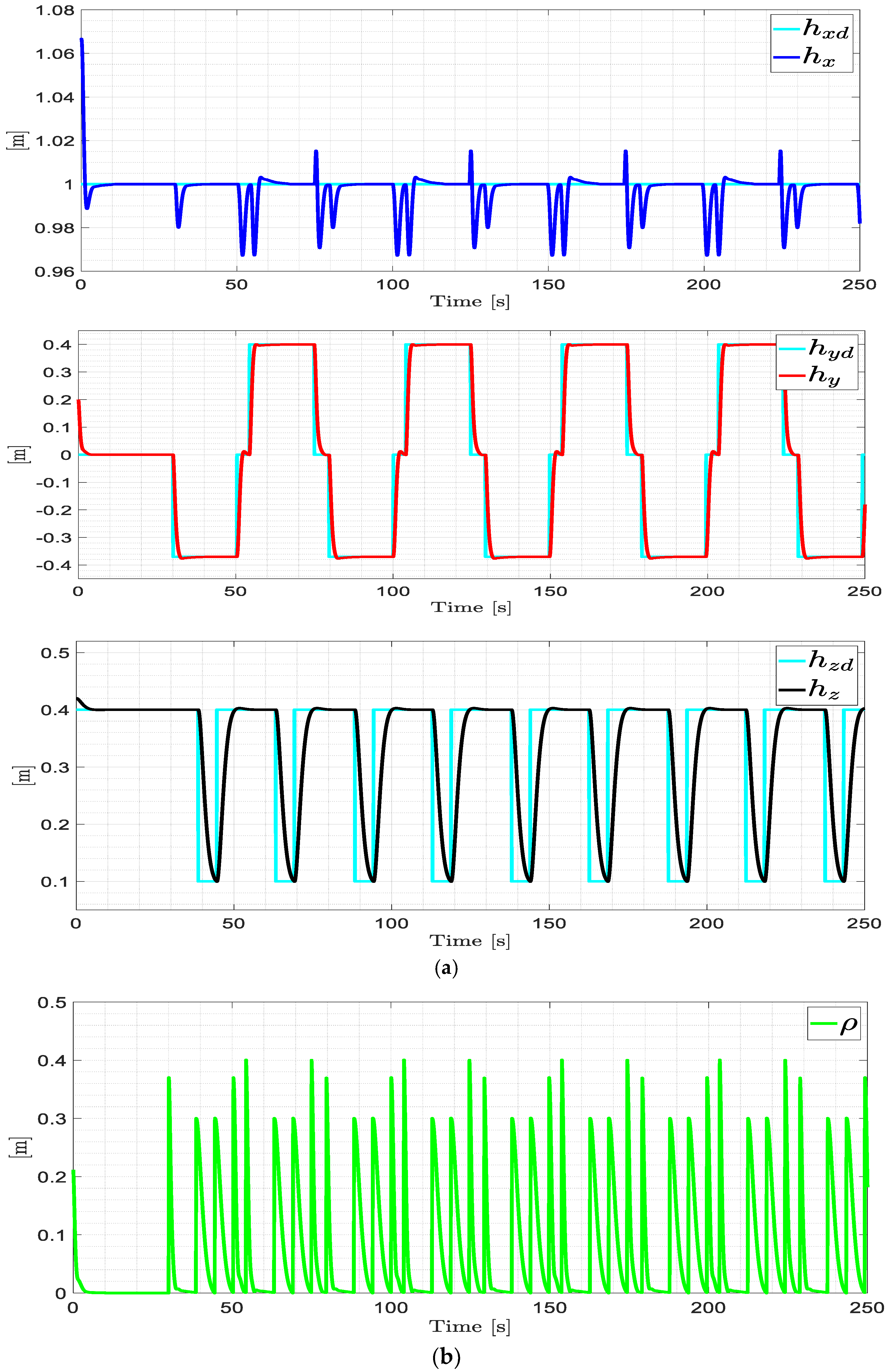
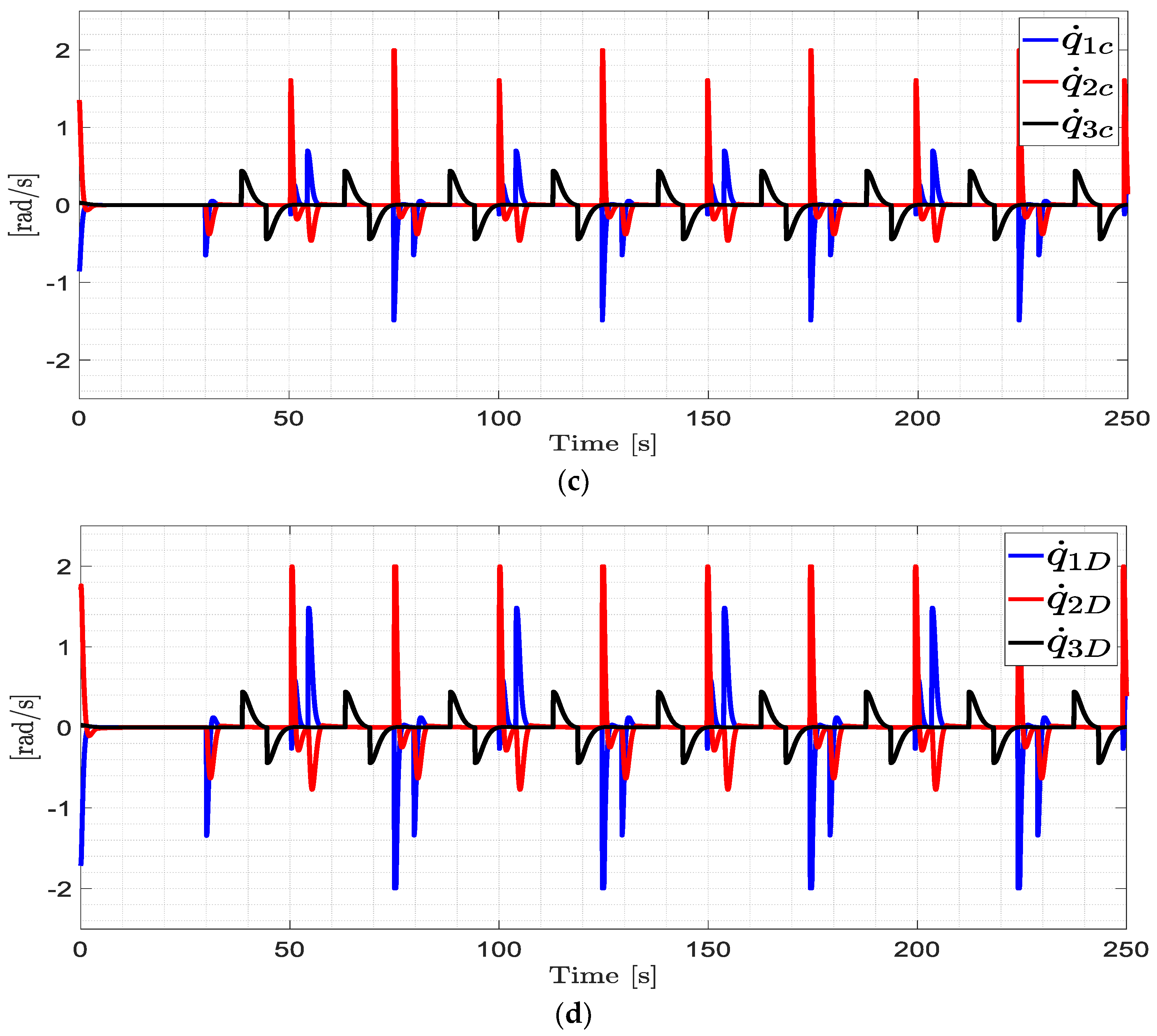
6.3. Implementation of the Control Algorithm
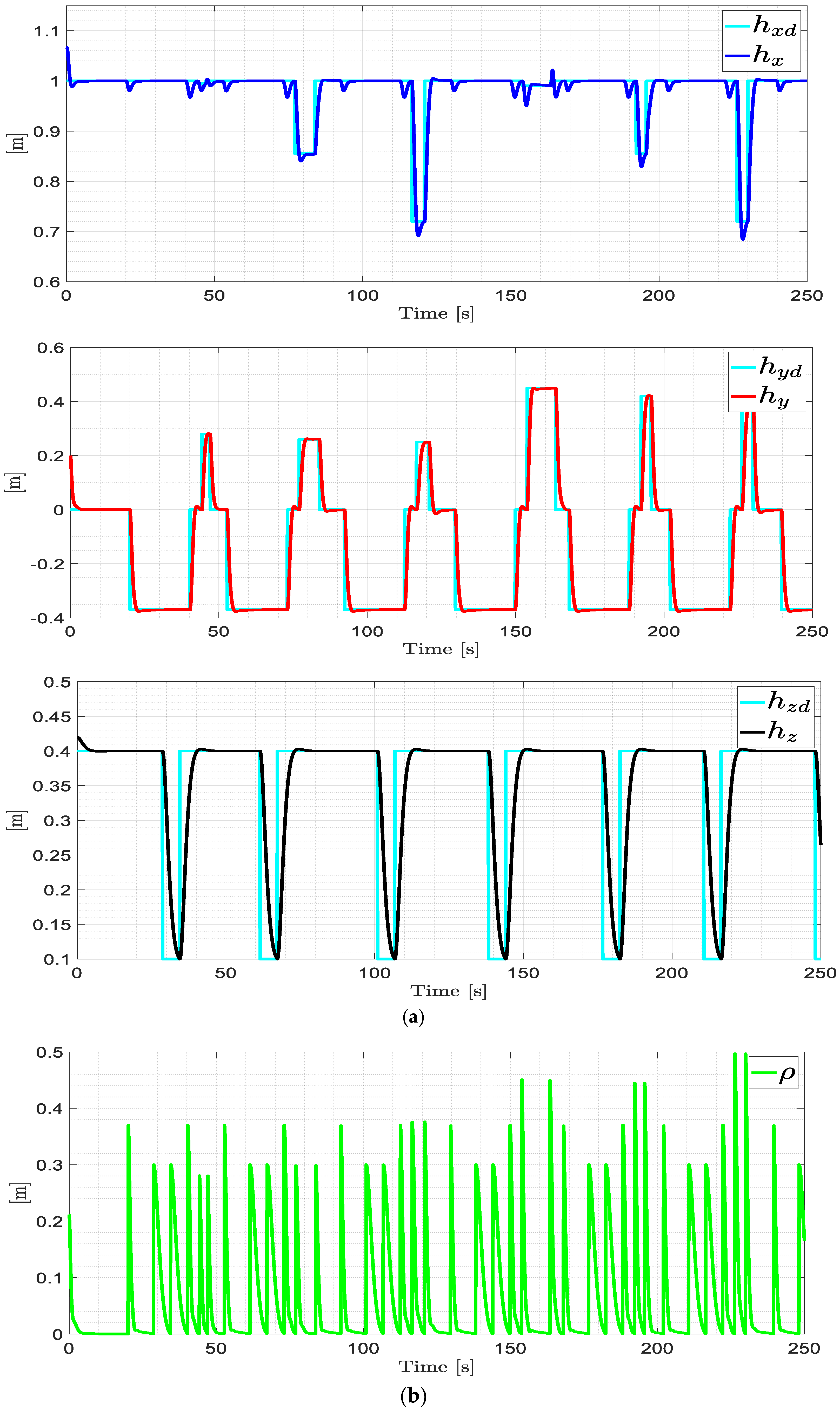
6.4. Industrial Environment
6.5. Implementation of the Control Algorithm
6.6. Usability of the Virtual Training System
7. Conclusions
Author Contributions
Funding
Acknowledgments
Conflicts of Interest
References
- Mite, L.B.; Mariela, C.V.M.; Salvatierra, D.M.; Ponce, K.A.Q. Análisis de los niveles de automatización de los procesos de producción de cacao. J. Bus. Entrep. Stud. 2020, 4, 2–2020. [Google Scholar]
- Zheng, T.; Ardolino, M.; Bacchetti, A.; Perona, M. The applications of Industry 4.0 technologies in manufacturing context: A systematic literature review. Int. J. Prod. Res. 2021, 59, 1922–1954. [Google Scholar] [CrossRef]
- Kurt, R. Industry 4.0 in terms of industrial relations and its impacts on labour life. Procedia Comput. Sci. 2019, 158, 590–601. [Google Scholar] [CrossRef]
- Karabegović, I. The role of industrial and service robots in the 4th industrial revolution—“Industry 4.0”. Acta Tech. Corviniensis-Bull. Eng. 2018, 11, 11–16. [Google Scholar]
- Müller, C. World Robotics 2022, Industrial Robots; IFR Statistical: Frankfurt, Germany, 2022; pp. 12–16. [Google Scholar]
- Sin, S.T.; Caro, J.Á.G. La robótica industrial en el ámbito de la automatización global: Estado actual y tendencias. Técnica Ind. 2014, 306, 26–39. [Google Scholar]
- D’Imperio, S.; Berruti, T.M.; Gastaldi, C.; Soccio, P. Tunable Vibration Absorber Design for a High-Precision Cartesian Robot. Robotics 2022, 11, 103. [Google Scholar] [CrossRef]
- Wu, M.; Mei, J.; Zhao, Y.; Niu, W. Vibration reduction of delta robot based on trajectory planning. Mech. Mach. Theory 2020, 153, 104004. [Google Scholar] [CrossRef]
- Balbuena, J.; Hilario, J.; Vargas, I.; Manzanares, R.; Cuellar, F. Design of a 2-dof delta robot for packaging and quality control of processed meat products. In 2018 Latin American Robotic Symposium, 2018 Brazilian Symposium on Robotics (SBR) and 2018 Workshop on Robotics in Education (WRE); IEEE: Piscataway, NJ, USA, 2018; pp. 201–206. [Google Scholar]
- Su, H.; Qi, W.; Hu, Y.; Karimi, H.R.; Ferrigno, G.; De Momi, E. An incremental learning framework for human-like redundancy optimization of anthropomorphic manipulators. IEEE Trans. Ind. Inform. 2020, 18, 1864–1872. [Google Scholar] [CrossRef]
- Devaraja, R.R.; Maskeliūnas, R.; Damaševičius, R. AISRA: Anthropomorphic Robotic Hand for Small-Scale Industrial Applications. In Proceedings of the Computational Science and Its Applications–ICCSA 2020: 20th International Conference, Cagliari, Italy, 1–4 July 2020; Part I 20. Springer International Publishing: Berlin/Heidelberg, Germany, 2020; pp. 746–759. [Google Scholar]
- Xie, B.; Qi, Y.; Su, W. RBF Network Adaptive Control of SCARA Robot Based on Fuzzy Compensation. In Journal of Physics: Conference Series; IOP Publishing: Bristol, UK, 2020; Volume 1650, p. 032006. [Google Scholar]
- Kutlu Gündoğdu, F.; Kahraman, C. Spherical fuzzy analytic hierarchy process (AHP) and its application to industrial robot selection. In Intelligent and Fuzzy Techniques in Big Data Analytics and Decision Making: Proceedings of the INFUS 2019 Conference, Istanbul, Turkey, 23–25 July 2019; Springer International Publishing: Berlin/Heidelberg, Germany, 2020; pp. 988–996. [Google Scholar]
- Zhi, H.; Nai-Yong, S. Cost-benefit analysis on remote maintenance for industrial robot. In Journal of Physics: Conference Series; IOP Publishing: Bristol, UK, 2020; Volume 1676, p. 012210. [Google Scholar]
- Gutiérrez, S.G.M.; Pazarán, A.C.; Mejía, R.G.; Moreno, L.N.O. Desarrollo de plataforma para implementación de robots colaborativos. Visión Electrón. 2018, 12, 22–31. [Google Scholar] [CrossRef] [Green Version]
- Lu, W.; Tang, B.; Wu, Y.; Lu, K.; Wang, D.; Wang, X. A new position detection and status monitoring system for joint of SCARA. IEEE/ASME Trans. Mechatron. 2020, 26, 1613–1623. [Google Scholar] [CrossRef]
- Ceballos, V.E. Industria 4.0, la gran oportunidad. Econ. Aragonesa 2016, 109. [Google Scholar]
- Kugler, P. When less is more: Coordinating innovation in open versus closed source software development. Int. J. Entrep. Small Bus. 2019, 37, 87–108. [Google Scholar] [CrossRef]
- Roldán, J.J.; Peña-Tapia, E.; Garzón-Ramos, D.; de León, J.; Garzón, M.; del Cerro, J.; Barrientos, A. Multi-robot systems, virtual reality and ROS: Developing a new generation of operator interfaces. Robot. Oper. Syst. Complet. Ref. 2019, 3, 29–64. [Google Scholar]
- Ciesla, R.; Ciesla, R. Freeware Game Engines. Most. Codeless Game Dev. New Sch. Game Engines 2017, 97–121. [Google Scholar]
- Garg, G.; Kuts, V.; Anbarjafari, G. Digital twin for fanuc robots: Industrial robot programming and simulation using virtual reality. Sustainability 2021, 13, 10336. [Google Scholar] [CrossRef]
- Ruiz, R.J.; Saravia, J.L.; Andaluz, V.H.; Sánchez, J.S. Virtual Training System for Unmanned Aerial Vehicle Control Teaching–Learning Processes. Electronics 2022, 11, 2613. [Google Scholar] [CrossRef]
- Ortiz, J.S.; Palacios-Navarro, G.; Andaluz, V.H.; Guevara, B.S. Virtual reality-based framework to simulate control algorithms for robotic assistance and rehabilitation tasks through a standing wheelchair. Sensors 2021, 21, 5083. [Google Scholar] [CrossRef]
- Gallardo, C.; Pogrebnoy, A.; Varela-Aldás, J. Development and Use of Dynamic Link Libraries Generated Under Various Calling Conventions. In Information Technology and Systems: ICITS 2021; Springer International Publishing: Berlin/Heidelberg, Germany, 2021; Volume 1, pp. 220–232. [Google Scholar]
- Andaluz, V.; Chicaiza, F.; Gallardo, C.; Quevedo, W.; Varela, J.; Sánchez, J.S.; Arteaga, O. Unity3D-MatLab Simulator in Real Time for Robotics Applications. Augmented Reality, Virtual Reality, and Computer Graphics. LNCS 2016, 9768, 246–263. [Google Scholar]
- Rossomando, F.G.; Soria, C.M. Adaptive neural sliding mode control in discrete time for a SCARA robot arm. IEEE Lat. Am. Trans. 2016, 14, 2556–2564. [Google Scholar] [CrossRef]
- Urrea, C.; Kern, J. A new model for analog servo motors. Simulations and experimental results. Can. J. Autom. Control. Intell. Syst. 2011, 2, 29–38. [Google Scholar]
- Jorque, B.S.; Mollocana, J.D.; Ortiz, J.S.; Andaluz, V.H. Mobile manipulator robot control through virtual hardware in the loop. In Trends and Applications in Information Systems and Technologies; Springer International Publishing: Berlin/Heidelberg, Germany, 2021; Volume 19, pp. 80–91. [Google Scholar]
- Herrera, K.A.; Rocha, J.A.; Silva, F.M.; Andaluz, V.H. Training systems for control of mobile manipulator robots in augmented reality. In 2020 15th Iberian Conference on Information Systems and Technologies (CISTI); IEEE: Piscataway, NJ, USA, 2020; pp. 1–7. [Google Scholar]
- Andaluz, V.; Roberti, F.; Toibero, J.M.; Carelli, R. Adaptive unified motion control of mobile manipulators. Control Eng. Pract. 2012, 20, 1337–1352. [Google Scholar] [CrossRef]
- Paz, J.A.M.; Gómez, M.Y.M.; Rosas, S.C. Análisis sistemático de información de la Norma ISO 25010 como base para la implementación en un laboratorio de Testing de software en la Universidad Cooperativa de Colombia Sede Popayán. In Memorias de Congresos; Revistas UTP: Bogotá, Colombia, 2017; pp. 149–154. [Google Scholar]
- Peruzzini, M.; Grandi, F.; Cavallaro, S.; Pellicciari, M. Using virtual manufacturing to design human-centric factories: An industrial case. Int. J. Adv. Manuf. Technol. 2021, 115, 873–887. [Google Scholar] [CrossRef]
- Teneda, F.I.; Villacís, J.I.; Espinosa, E.G.; Andaluz, V.H. Conversational agent for industrial processes through virtual environments. In Trends and Applications in Information Systems and Technologies; Springer International Publishing: Berlin/Heidelberg, Germany, 2021; Volume 49, pp. 218–229. [Google Scholar]
- Arthana, I.K.R.; Pradnyana, I.M.A.; Dantes, G.R. Usability testing on website wadaya based on ISO 9241-11. In Journal of Physics: Conference Series; IOP Publishing: Bristol, UK, 2019; Volume 1165, p. 012012. [Google Scholar]
- Brooke, J. SUS-A quick and dirty usability scale. Usability Eval. Ind. 1996, 189, 4–7. [Google Scholar]


| Gain Parameters | ||
|---|---|---|
| Gain Parameters | ||
|---|---|---|
| Robot A | ||
| Robot B | ||
| No. | Questions | Score | Operation |
|---|---|---|---|
| 1 | I think I would like to use this virtual training system frequently. | 4 | 4 − 1 = 3 |
| 2 | I found the training system unnecessarily complex. | 1 | 5 − 1 = 4 |
| 3 | I thought the training system was easy to use. | 4 | 4 − 1 = 3 |
| 4 | I think I would need the support of a specialist to be able to use this system. | 1 | 5 − 1 = 4 |
| 5 | I found that the various functions of this system were well integrated. | 5 | 5 − 1 = 4 |
| 6 | I thought there was too much inconsistency in this virtual training system. | 2 | 5 − 2 = 3 |
| 7 | I imagine most people would learn to use this system very quickly. | 4 | 4 − 1 = 3 |
| 8 | I found the virtual training system very cumbersome to use. | 1 | 5 − 1 = 4 |
| 9 | I felt very comfortable using the virtual training system. | 5 | 5 − 1 = 4 |
| 10 | I needed to learn a lot of things before I can use this virtual training system. | 4 | 4 − 1 = 3 |
| Total |
Disclaimer/Publisher’s Note: The statements, opinions and data contained in all publications are solely those of the individual author(s) and contributor(s) and not of MDPI and/or the editor(s). MDPI and/or the editor(s) disclaim responsibility for any injury to people or property resulting from any ideas, methods, instructions or products referred to in the content. |
© 2023 by the authors. Licensee MDPI, Basel, Switzerland. This article is an open access article distributed under the terms and conditions of the Creative Commons Attribution (CC BY) license (https://creativecommons.org/licenses/by/4.0/).
Share and Cite
Ipiales, J.S.; Araque, E.J.; Andaluz, V.H.; Naranjo, C.A. Virtual Training System for the Teaching-Learning Process in the Area of Industrial Robotics. Electronics 2023, 12, 974. https://doi.org/10.3390/electronics12040974
Ipiales JS, Araque EJ, Andaluz VH, Naranjo CA. Virtual Training System for the Teaching-Learning Process in the Area of Industrial Robotics. Electronics. 2023; 12(4):974. https://doi.org/10.3390/electronics12040974
Chicago/Turabian StyleIpiales, Jordan S., Edison J. Araque, Víctor H. Andaluz, and César A. Naranjo. 2023. "Virtual Training System for the Teaching-Learning Process in the Area of Industrial Robotics" Electronics 12, no. 4: 974. https://doi.org/10.3390/electronics12040974