1. Introduction
The increasing integration of wind generation will bring significant challenges to the system frequency stability since power converter interfaced doubly-fed induction generators (DFIGs, Type 3 wind turbine generator) decouple the rotor speed from the instantaneous power system frequency [
1,
2,
3] and the system inertia response will be weakened [
4,
5]. Therefore, not only do the maximum instantaneous system frequency excursion (ISFE, Δ
f), but also the maximum rate of change of the frequency (
df/dt) become worse, but they might increase the possibilities to trigger the relays of under- and over-system frequency [
6,
7]. In fact, DFIG retains a wider rotor operation range than that a traditional synchronous generator (TSG) due to the characteristics of the DFIG; thus, DFIGs can be a better option of the inertial control for supporting the frequency [
8].
There are three types for the present inertial response imitation (IRI) strategies of DFIGs, which are characterized by the form of the reference for active power:
df/dt response; ∆
f response; and fixed power trajectory response [
9,
10,
11,
12,
13,
14,
15,
16,
17,
18]. The references in [
9,
10] modify the additional control signal, which is proportional to
df/dt to imitate the inertial response (
df/dt response). The authors of [
11,
12] suggested an additional supplementary control that was proportional to ∆
f to emulate the droop response. The IRI strategy with the fixed power trajectory response is related to the preset power trajectories [
14,
15,
16].
As studied in [
13,
17], the intensity of the IRI strategy based on
df/dt and ∆
f mainly depends on the control coefficient. Once the coefficients are not defined appropriately, the intensity of the IRI strategy might be insufficient to contribute to the frequency response service inadequately. In contrast, stalling of the wind turbine is prone to being caused and then results in a large secondary system frequency drop (SSFD). To avoid the stalling of the DFIGs, speed-based coefficient-based IRI schemes are suggested [
11,
13]. The control coefficient is dependent on the rotor speed to provide a frequency support response for various speeds of the rotor. However, under large system frequency disturbances, the electric power grid requires more active power from the DFIG to counterbalance the power imbalance, so special attention should be paid to assigning the control gains.
The speed of the rotor should be regained to the initial operation state after sustaining the instantaneous system frequency. If there is no additional output to offset the short power absorbed to restore the rotor speed, a severe SSFD may produce, and even be lower than the maximum ∆
f caused by frequency disturbance [
5]. With the proliferation of wind generation, the existing schemes can improve the maximum ∆
f, mitigating the SSFD turns that are a crucial issue for the deployment of the IRI schemes. Consequently, the trade-off between the rotor speed recovery (RSR) and reducing SSFD is necessary to be developed [
18]. To reduce the SSFD, an extended state observer-based IRI scheme was suggested in [
18]. A two-stage variable coefficient-based IRI strategy was addressed [
10]. However, the performances were dependent on the pre-determined training logic of the fuzzy control. The strategy in [
19] suggests a dynamic RSR-oriented droop control to reduce the SSFD with a comprehensive function. Thus, special study should be paid to determine the control coefficient to achieve the trade-off between RSR and reducing SSFD.
Based on the shortcomings of the conventional IRI scheme, the contributions of this study are that (1) the coupling relationship between the control coefficient of DFIGs and the frequency deviation can be established by using the exponential function so that the control coefficient becomes large with the increasing frequency deviations and sizes of disturbance; and (2) the exponential function has been employed to schedule the dynamic control coefficient to alleviate the negative effects of RSR on the instantaneous system frequency.
The rest of this paper is organized as follows.
Section 2 introduces the modeling of DFIG. The proposed IRI and RSR schemes are proposed and verified in
Section 3 and
Section 4.
Section 5 and
Section 6 draw the discussions and conclusions, respectively.
2. Modeling of a DFIG
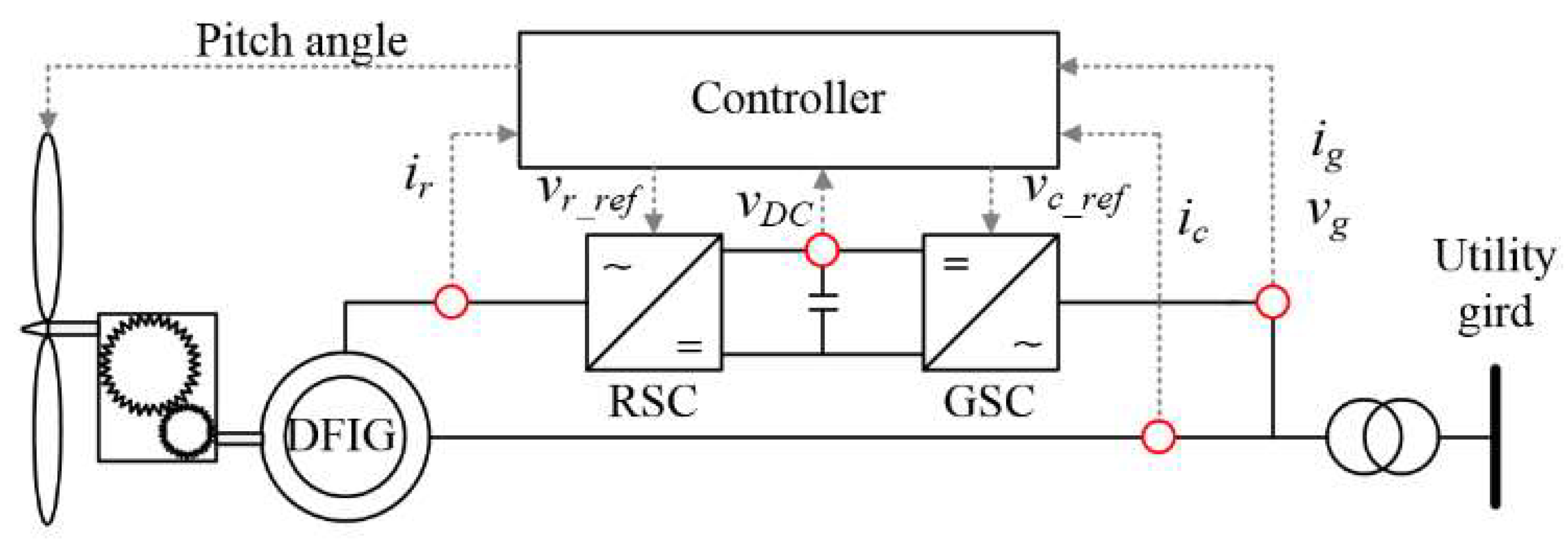
The typical DFIG configuration model comprises a control system, wind turbine model, shaft model, power electronics, and induction generator (see
Figure 1).
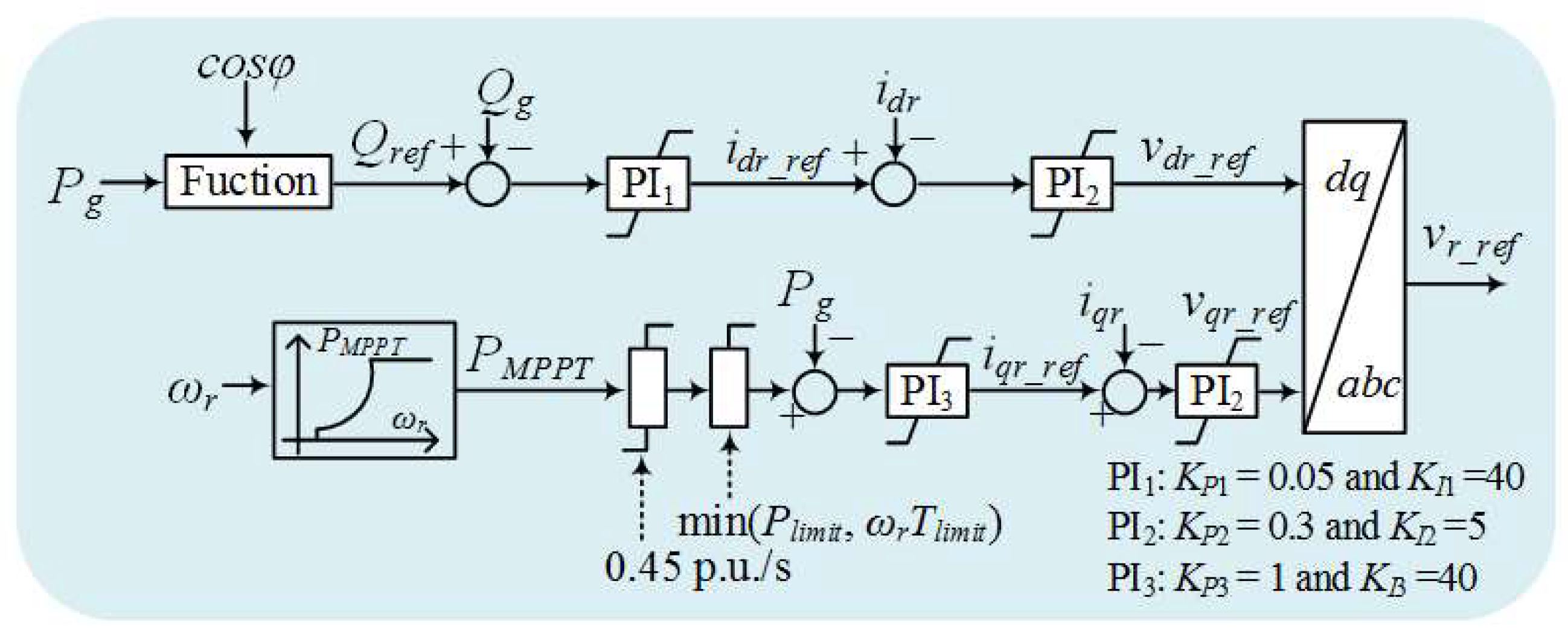
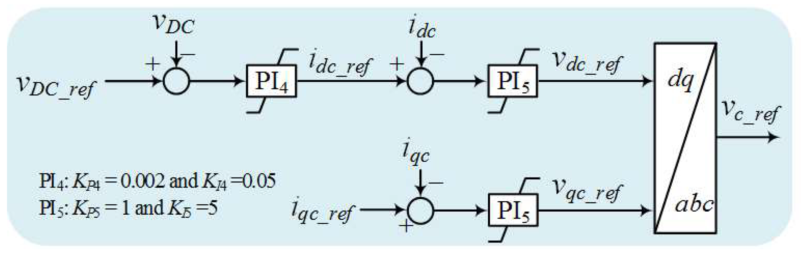
The control system, which comprises a rotor-side converter (RSC) and grid-side converter (GSC), determines the references and receives the measured values for voltage, power, DC-link voltage, and currents, as shown in
Figure 2 and
Figure 3. Active power control including the maximum power point tracking (MPPT) operation and inertial control are achieved in the RSC controller. The voltage of the DC-link is regulated by the GSC [
20].
The formula for the mechanical power is a function of air density (
ρ), rotor radius (
R), power coefficient (
cp), and wind speed (
vw), as in:
where
λ and
β mean the tip-speed ration and pitch angle, respectively.
The expression of
cp is as:
In Equation (1),
cp retains a maximum value (
cP, max) at the optimal tip-speed ratio (
λopt) for capturing the maximum
Pm. The power reference expression of the MPPT operation,
PMPPT, is expressed as in Equation (5) by substituting Equation (4) in Equation (1).
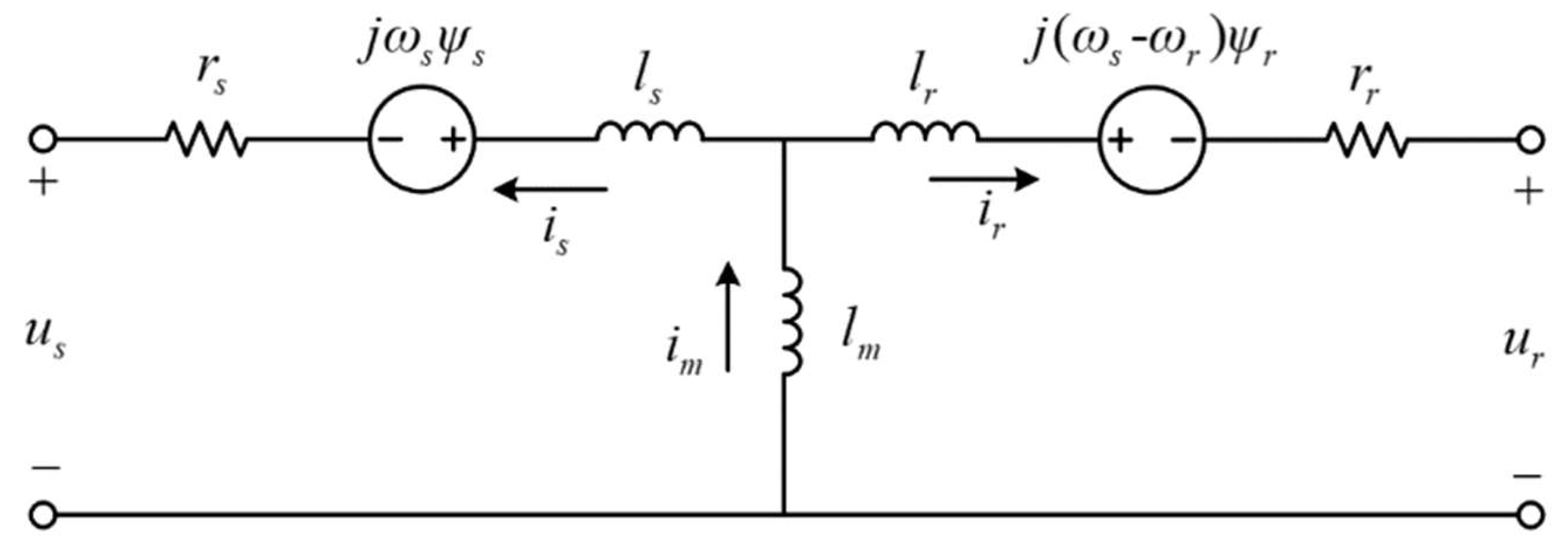
The electrical equivalent circuit of the DFIG is illustrated in
Figure 4. The stator and rotor voltage equations are represented by:
The stator and rotor winding flux linkages are written as:
The reactive power, active power, and torque are respectively expressed by
3. Innovative Inertial Response Imitation and Rotor Speed Recovery Control of a DFIG
3.1. Conventional Scheme #1
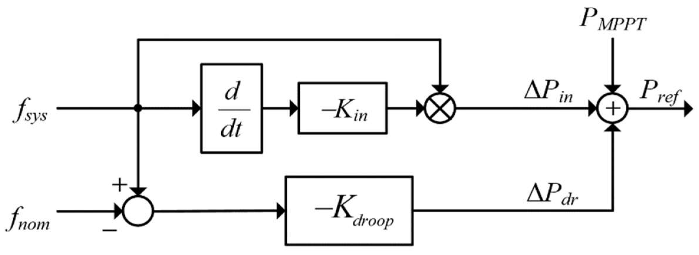
Figure 5 displays the structure of conventional scheme #1 (fixed gain scheme). The reference (
Pref) comprises the output for the
df/dt control loop (Δ
Pin, top loop), Δ
f control loop (Δ
Pdr, bottom loop), and MPPT control (
PMPPT), as in Equation (17). Before a frequency disturbance,
Pref is equal to
PMPPT; after a disturbance, Δ
Pin and Δ
Pdr, which are dependent on the measured system frequency, are added to
PMPPT.
Δ
Pin and Δ
Pdr can be expressed as
where
fsys represents the system frequency.
Kin and
Kdroop indicate the control gains for the
df/dt control loop and Δ
f control loop, respectively.
During the initial period of the frequency disturbance, ΔPin is dominant since the df/dt retains a large value; whereas ΔPdr is dominant around the frequency nadir. In addition, ΔPin decreases with the df/dt and then decreases to zero when the steady-state is achieved. Thus, the combination of the df/dt and Δf loops can boost the frequency support capability.
For conventional scheme #1, with the increasing control coefficient, the released energy to the grid becomes large; however, the frequency nadir might become low since the significant second frequency drop (SFD) is caused due to excessive released energy. Furthermore, the DFIG operates in a mode deviating from the MPPT operation due to the Δf, which adversely affects the economic operation of the DFIG. In addition, when the conventional RSR schemes are implemented, the SFD is inevitable due to the sudden power drop. Thus, conventional scheme #1 has two issues, as follows: (I) difficulties arise in determining the control coefficient; and (II) SSFD might be caused.
3.2. Conventional Scheme #2
The expression of kinetic energy available from the rotational rotor of the DFIG is:
where
HDFIG represents the inertia for the DFIG;
ω0 and
ωmin are
ωr before frequency disturbances and minimum value, respectively.
In [
13], to boost the frequency support capability and avoid stalling of the wind turbine, the control gain for the frequency deviation control loop is defined to be proportional to
Eavail, which can be expressed as:
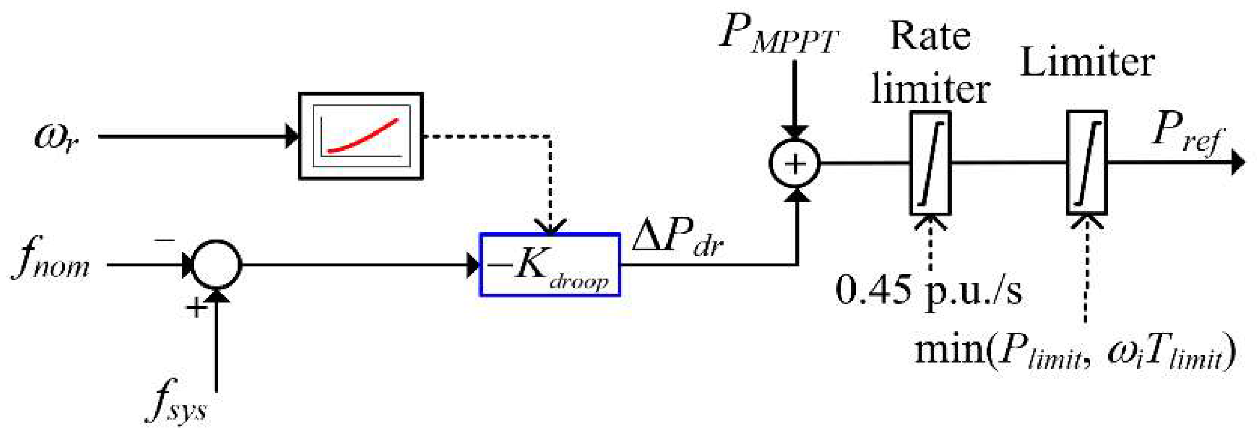
According to Equation (21), as shown in
Figure 6, the expression of
Kdroop for conventional scheme #2 is as follows:
where
δ is the operating condition factor of the DFIG and regulate the benefits to boosting the frequency support capability.
There are two features of Equation (22). The first is that
Kdroop is zero when
ωr = ωmin. As a result, conventional scheme #2 can avoid the stalling of the wind turbine. The second is that
Kdroop increases with the rotor speed to effectively enhance the frequency support capability for various wind conditions (refer to [
13]).
However, under various sizes of disturbance, Δf is different so that various additional powers are required from the DFIG. With increasing frequency deviation, more active power is required from the grid, particularly under large disturbances. Conventional scheme #2 might be unable to sustain the system frequency effectively. Therefore, the implementation of conventional scheme #2 may face the following challenges: (I) a suitable control coefficient for various frequency disturbances; and (II) similar to conventional scheme #1, SSFD is caused to restore the rotor speed.
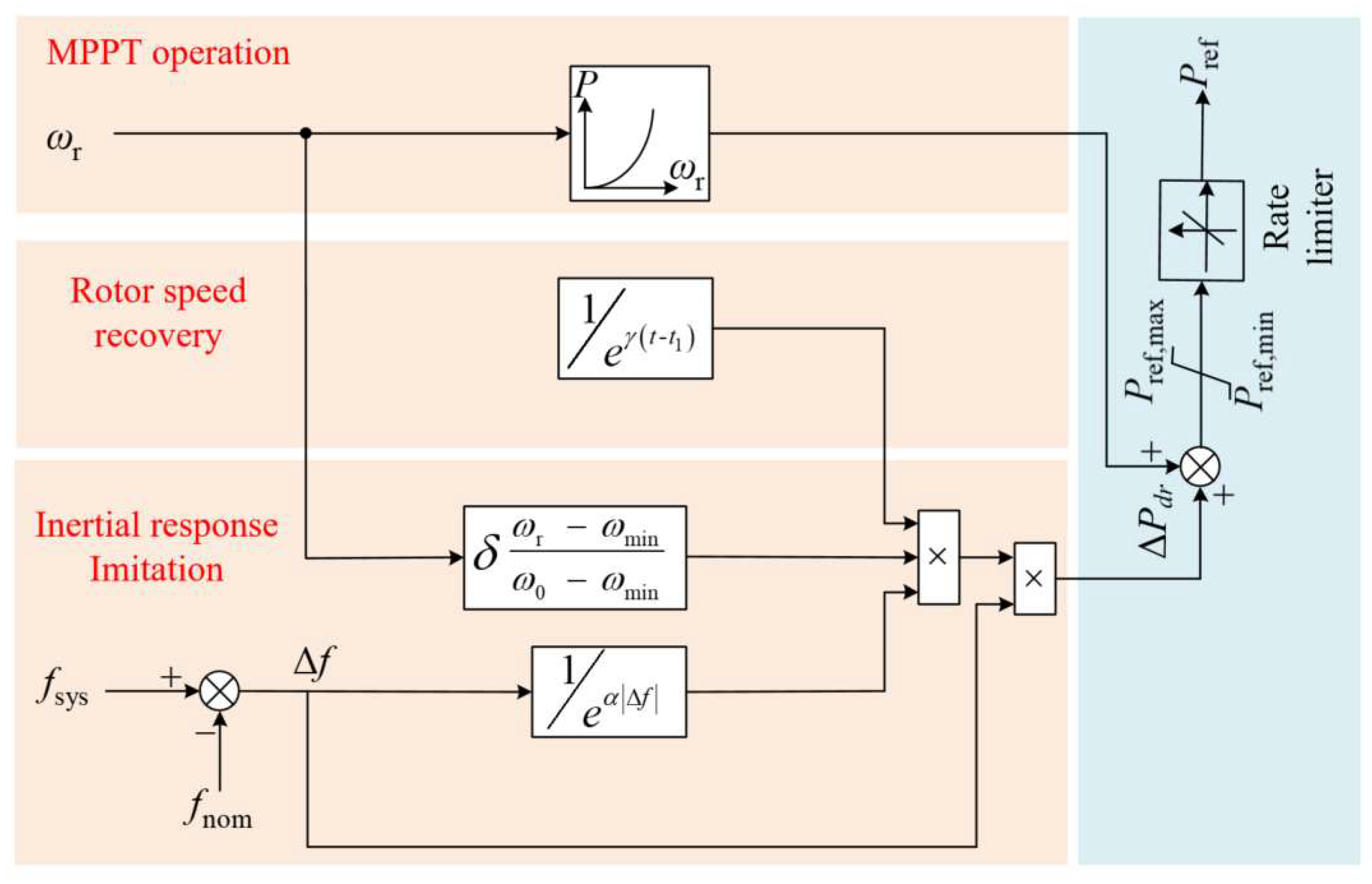
3.3. Proposed Inertial Response Imitation and Rotor Speed Recovery Control Scheme of a DFIG
To boost the frequency nadir and mitigate the negative influences of RSR on the system frequency, an adaptive control coefficient (ACC) was suggested, which was determined into two periods: an inertial response imitation period (
Ksup(
fsys,
ωr)), which aims to boost the frequency nadir, and the RSR period (
Krec(
t)), which aims to mitigate the negative influences of RSR on the system frequency (see
Figure 7).
3.3.1. Determining Control Coefficient for Inertial Response Imitation Period
Under various sizes of disturbance, a control coefficient should be determined that is suitable for the power deficit to improve the frequency support capability. Thus, to enhance the frequency support capability while avoiding the stalling of the DFIG, the control coefficient for the inertial response imitation period can be expressed as:
where
σ(
ωr) and
η(
fsys) are the operating conditions of the DFIG and the instantaneous system frequency, respectively. |Δ
f| indicates the absolute value of frequency deviation.
α reflects the frequency support term and adjusts the performance of boosting the frequency support capability.
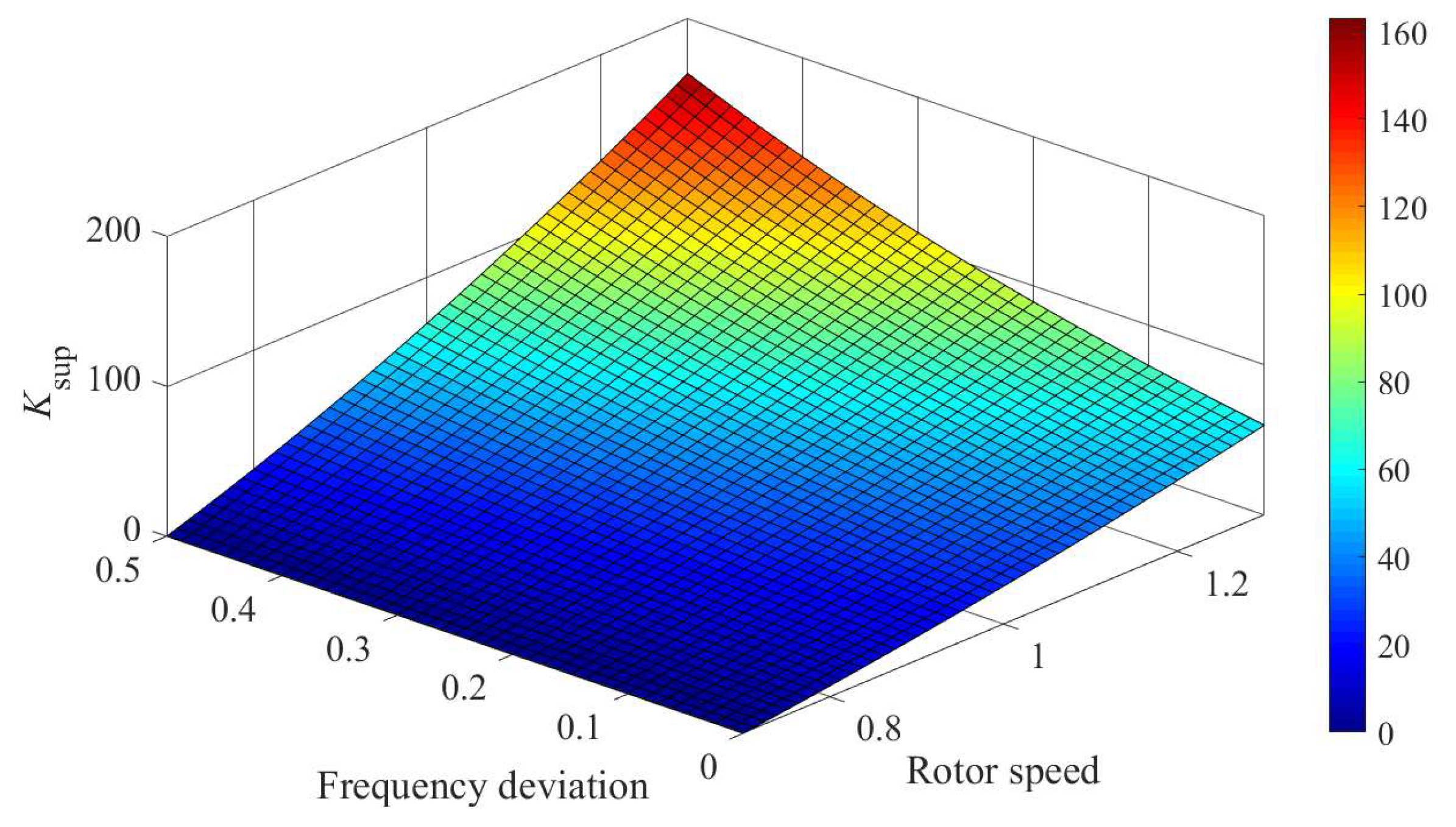
As shown in
Figure 8,
σ(
ωr) determines that
Ksup(
fsys,
ωr) is proportional to the rotor speed and is zero at
ωmin to avoid stalling of the DFIG and make use of the significant amount of available kinetic energy to support the frequency under various wind conditions.
η(
fsys) determines that
Ksup(
fsys,
ωr) is regulated by the |Δ
f|; thus, with the increase in |Δ
f|, a large value can be derived to reduce the ISFE under various disturbances.
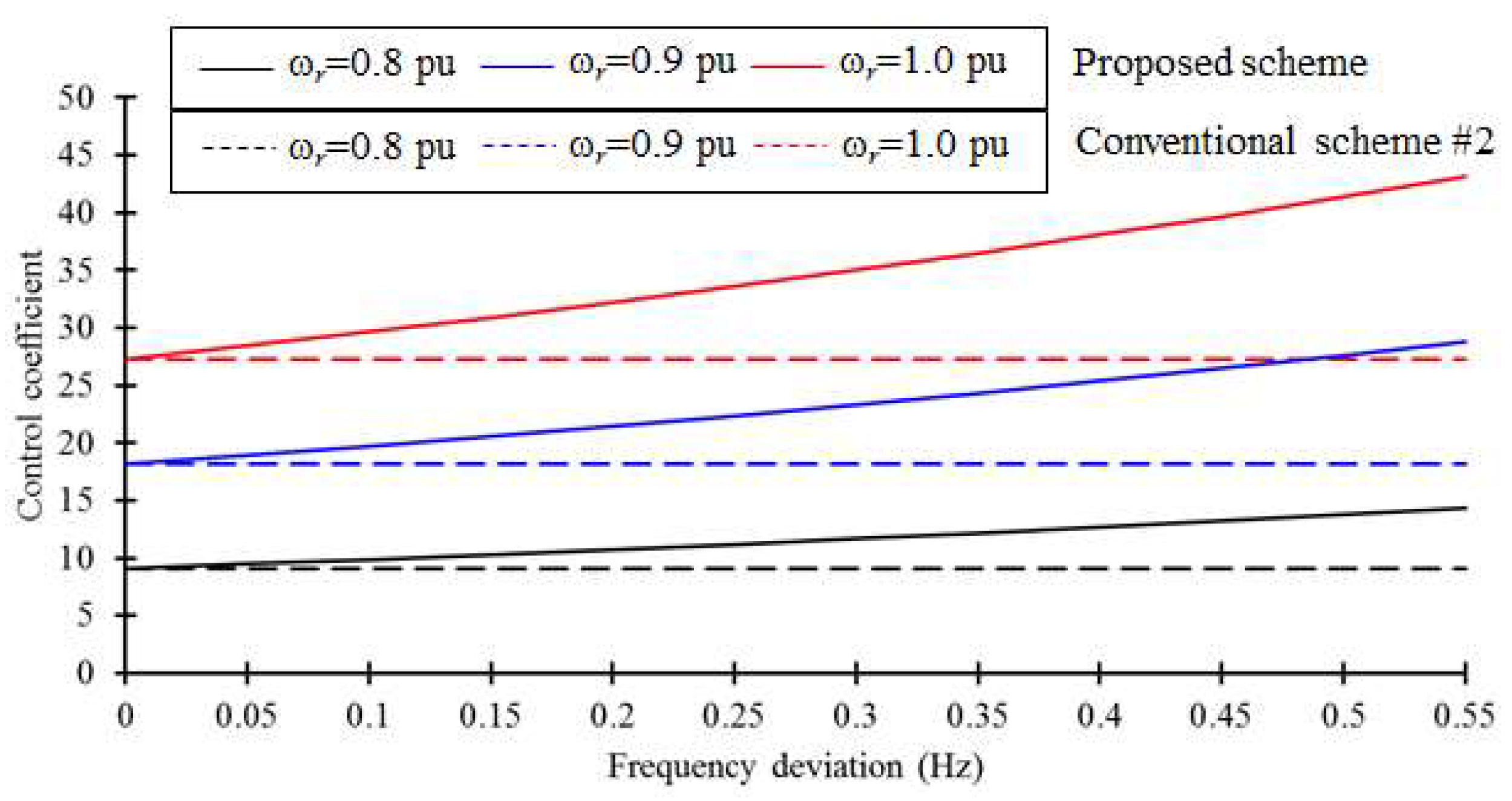
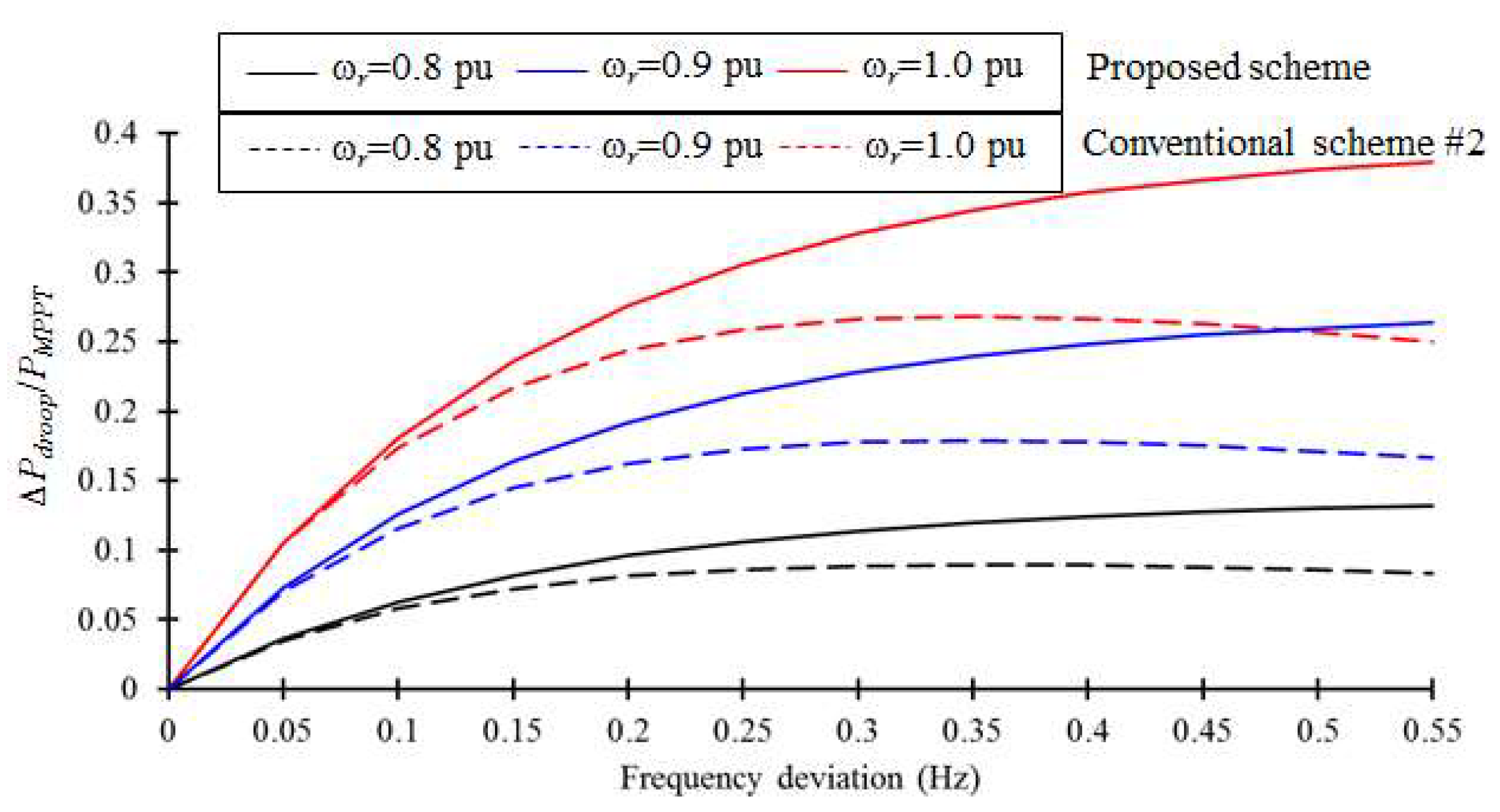
As studied in [
21], Δ
Pdr/
PMPPT is capable of reflecting the capability for reducing the maximum frequency deviation. As shown in
Figure 9 and
Figure 10, the comparison of the control coefficient and Δ
Pdr/
PMPPT of the proposed and conventional schemes at various frequency deviations are illustrated. It can be observed that
Ksup(
fsys,
ωr) and Δ
Pdr/
PMPPT are always more than those of the conventional inertial control scheme; furthermore, the differences become large so the proposed IRI scheme with ACC can boost the frequency support capability, particularly for the severe deviations in the system frequency.
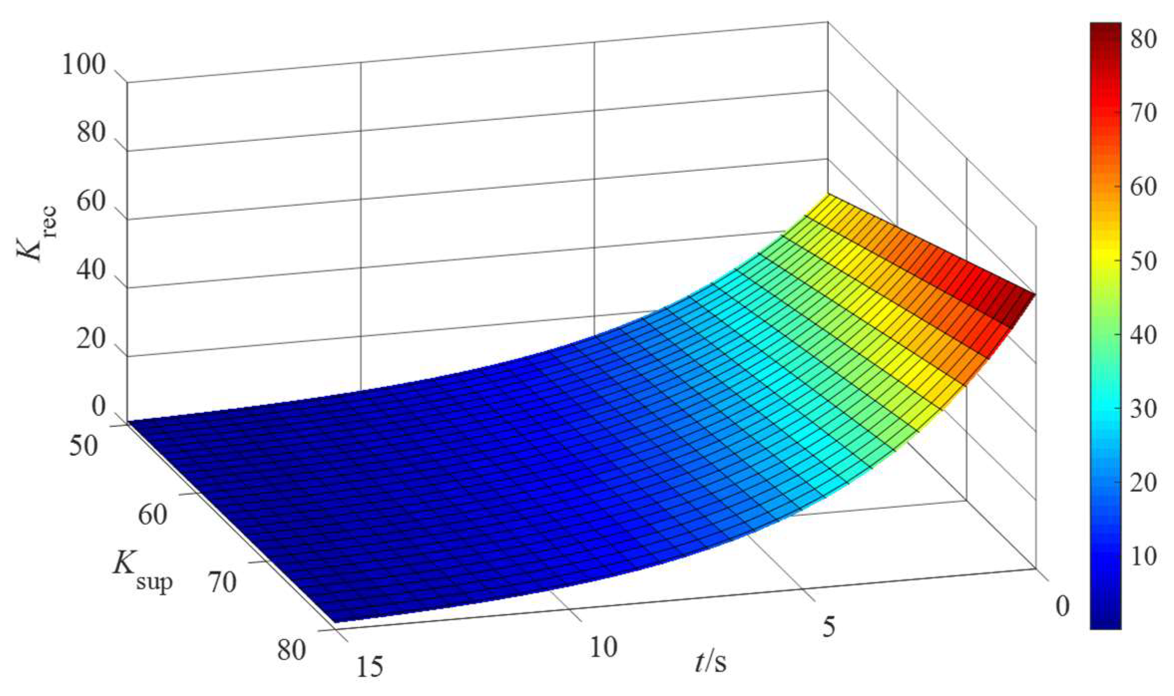
3.3.2. Determining Control Coefficient for RSR Period
During the RSR period, to avoid the SFD, the instantaneous decrease in the output power should be prevented [
17,
18]. To address this demand, an exponential function is employed to schedule the dynamic control coefficient
Krec(
t), as in:
where
t1 indicates the beginning of the RSR and
γ represents the regulating factor to adjust the scheduled time for decreasing the coefficient, as shown in
Figure 11.
Ksup(
t1) indicates the control coefficient at
t1.
As illustrated in Equation (26), it is obvious that the large γ can accelerate the RSR, but produce severe SFD. Therefore, γ should not be set as too large a value; otherwise, unexpected severe SFD is caused. The small enough γ can avoid the SSFD, but delays the period of RSR. Since the exponential based Krec cannot decrease to zero, Pref was changed to PMPPT 20 s after recovering the speed of the rotor.
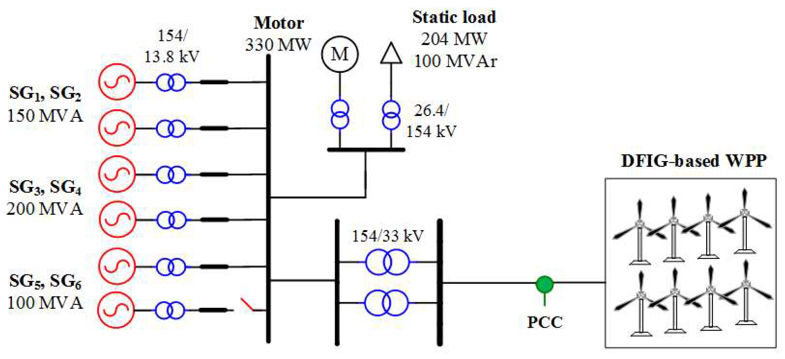
4. Model System
To study the effectiveness of the proposed IRI and RSR scheme, four cases with constant wind speeds under various wind speed conditions and disturbance were carried out using the test system shown in
Figure 12. As disturbances, SG
4, which generated 80 MW, was tripped out for Case 1 and Case 2, and SG
4, which generated 140 MW, was tripped out for Case 3 to Case 4.
The performance of the proposed inertial response emulation and RSR control scheme was compared to conventional scheme #2 [
11] (which is denoted as the conventional scheme in the simulation results) without the RSR and a conventional scheme with the proposed RSR. In the conventional inertial control scheme and proposed inertial control scheme, the value of
δ was set to 50 and
α for (23) was set to 100. γ was set to 0.12.
4.1. Case 1: Wind Speed = 10 m/s, Disturbance = 80 MW
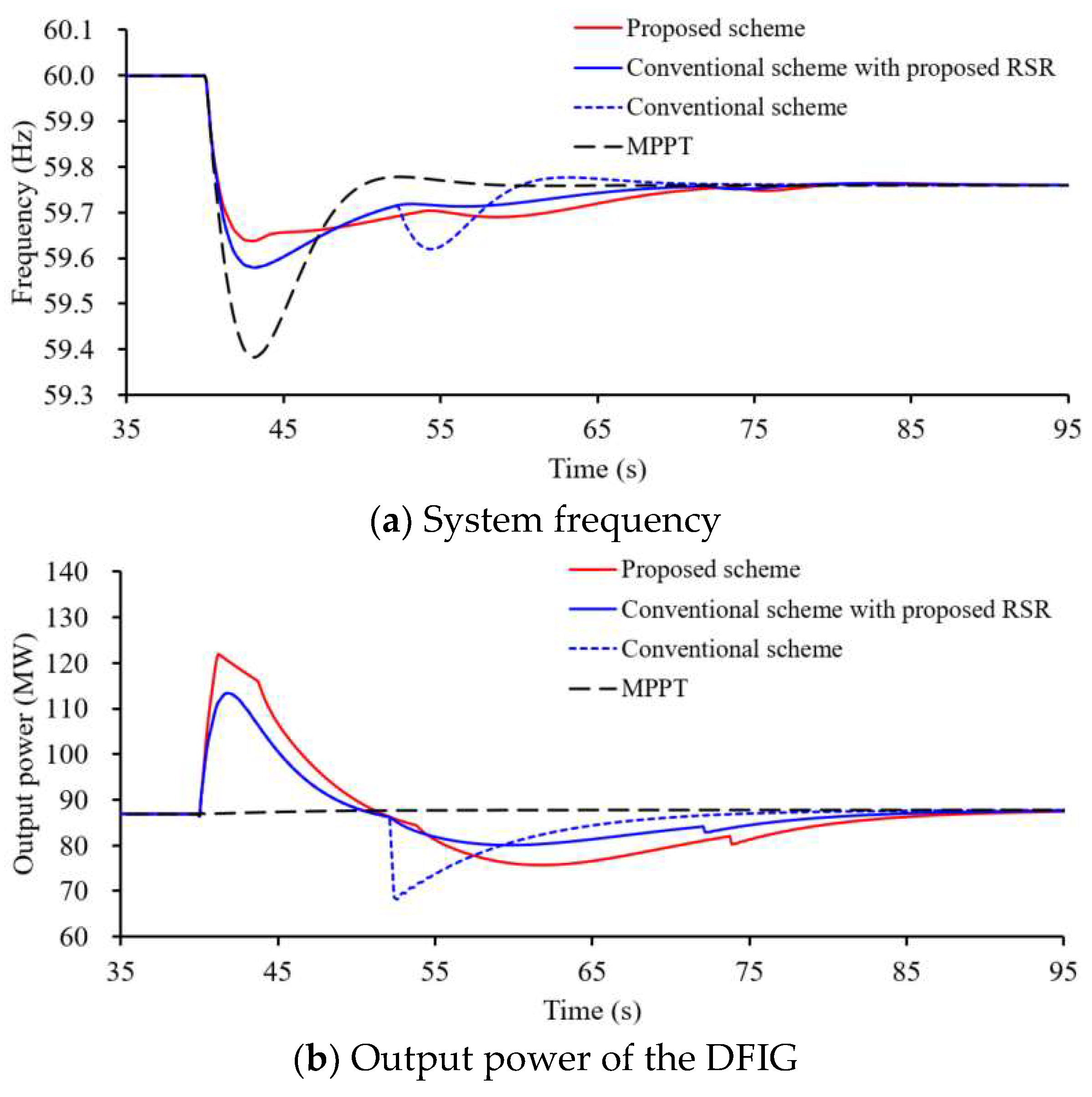
Figure 13 illustrates the results for Case 1. The frequency nadirs with the MPPT operation, conventional scheme, and proposed inertial control scheme were 59.378 Hz, 59.578 Hz, and 59.638 Hz, respectively. The frequency nadir for the proposed IRI scheme was the highest since the output power was significantly more than in the conventional scheme due to the control coefficient coupling with the frequency deviation, as illustrated in
Figure 13a,b.
In the conventional scheme, there was a small second frequency drop due to the less power drop during the RSR (see
Figure 13b), however, when the proposed RSR scheme was applied to the conventional scheme and the proposed scheme, the SFD could be minimized due to the smooth power drop, as indicated in
Figure 13a.
4.2. Case 2: Wind Speed = 8 m/s, Disturbance = 80 MW
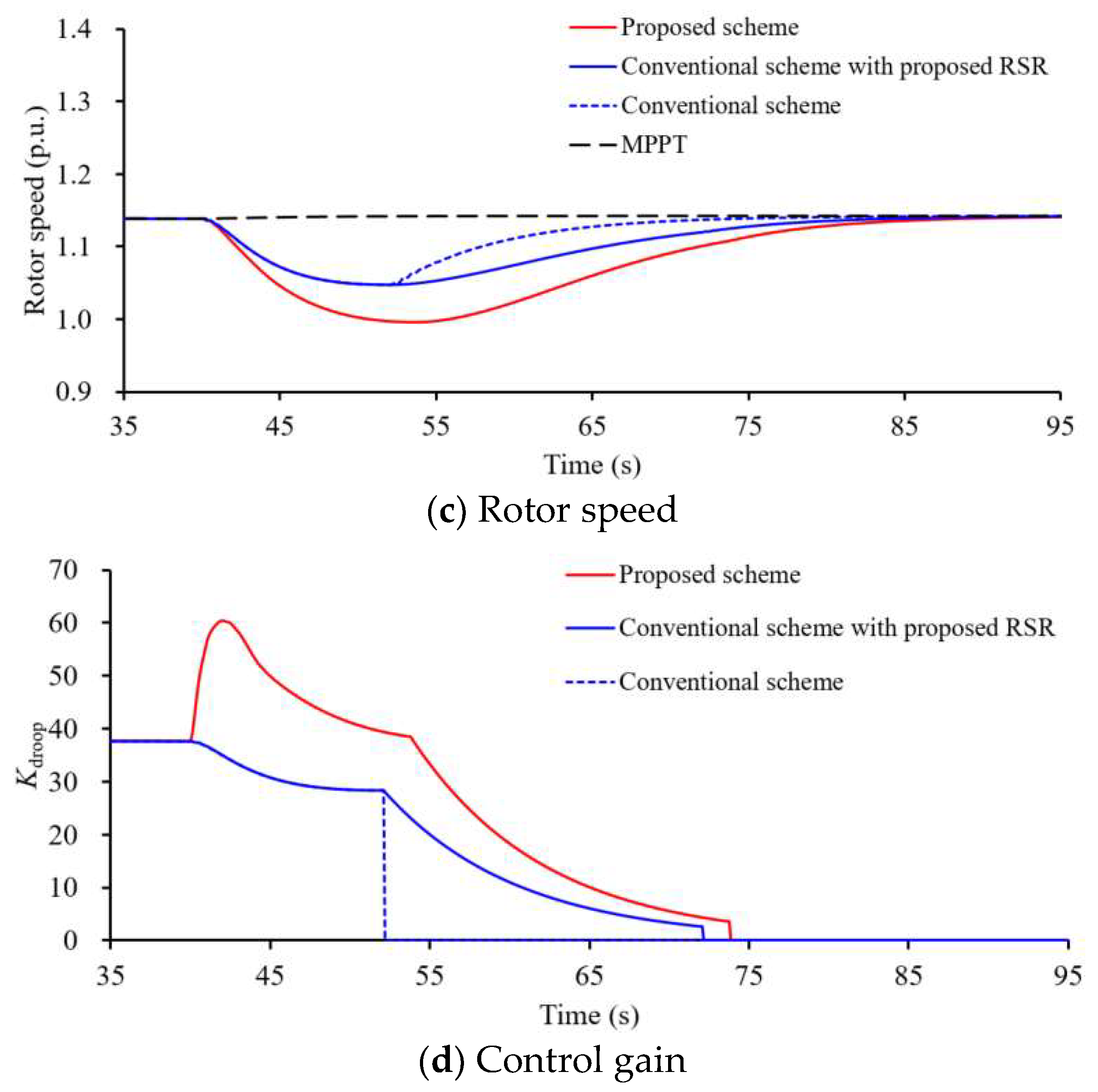
The maximum ISFE with MPPT operation was 0.628 Hz, which was almost the same as Case 1, since only synchronous generators support the dynamic frequency. However, the frequency nadirs with the conventional and proposed IRI schemes were 59.478 Hz and 59.549 Hz, respectively, which were less than in Case 1 due to the decreased rotating energy of the rotor, and the improvement in the frequency nadir for the proposed inertial control scheme was 0.071 Hz.
Since the gap between the power reference and the MPPT curve becomes small, less SFD of the conventional scheme is caused, as shown in
Figure 14a,b. As in Case 1, when the DFIG was implemented on the proposed RSR control coefficient on the conventional and proposed schemes, the SFD could be minimized by smoothly decreasing the output power.
4.3. Case 3: Wind Speed = 8 m/s, Disturbance = 140 MW
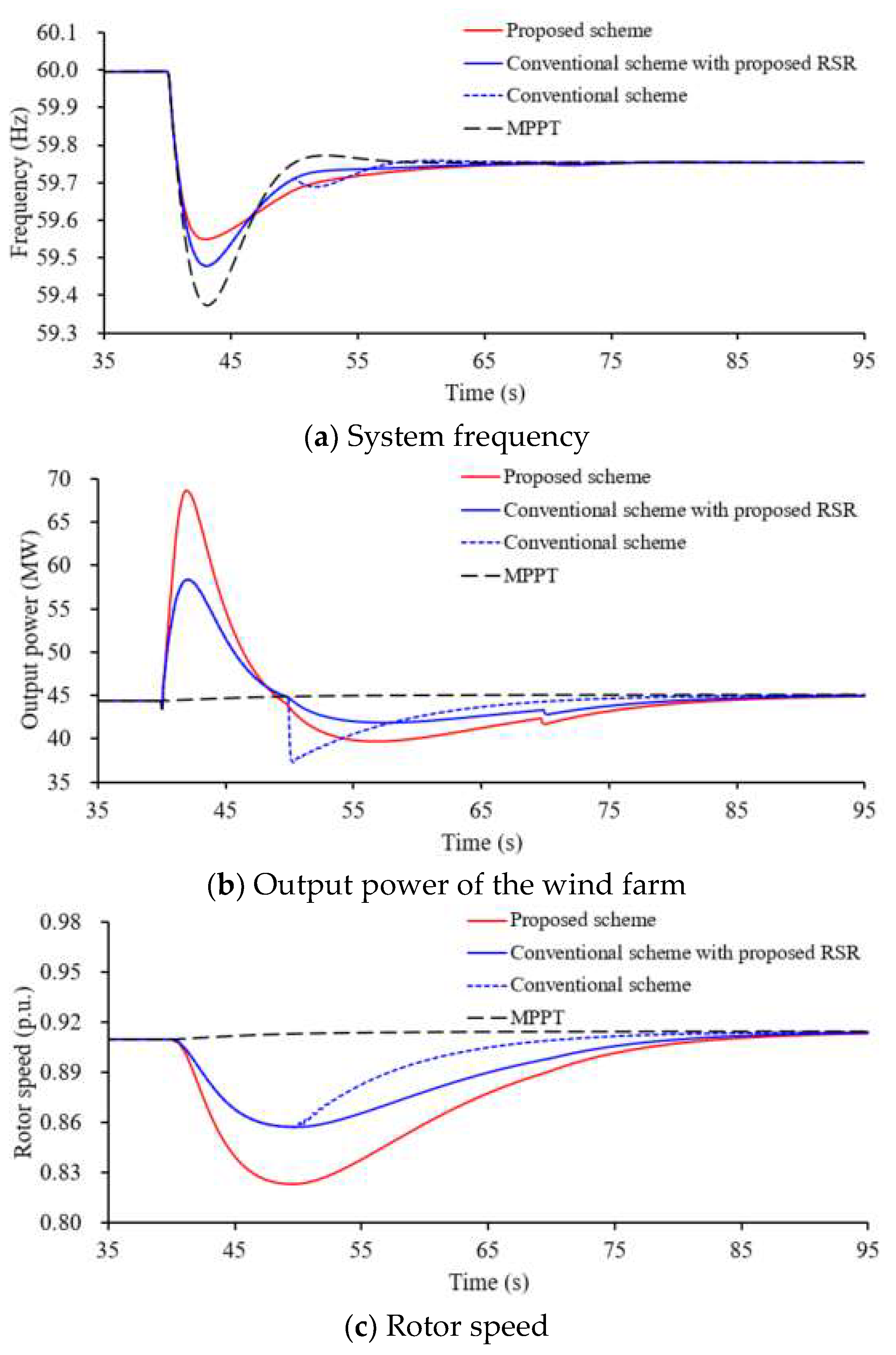
Compared to Case 2, a large disturbance occurred in this case. As a result, the frequency nadirs for all schemes, which were 58.886 Hz, 59.060 Hz, and 59.217 Hz, became lower. The improvement in the frequency nadir between the proposed and conventional IRI schemes was 0.105 Hz, since the proposed control coefficient became large with the increasing frequency deviation, as shown in
Figure 15d. Thus, the proposed IRI scheme can boost the frequency nadir, even though under a severe disturbance.
During the RSR period, a SFD of 59.477 Hz was caused in the conventional scheme due to the sudden power drop (see
Figure 15b). However, as in Case 3, when the proposed RSR scheme was applied on the conventional scheme and the proposed scheme, the SFD could be minimized due to the smooth power drop during the RSR period, as indicated in
Figure 15.
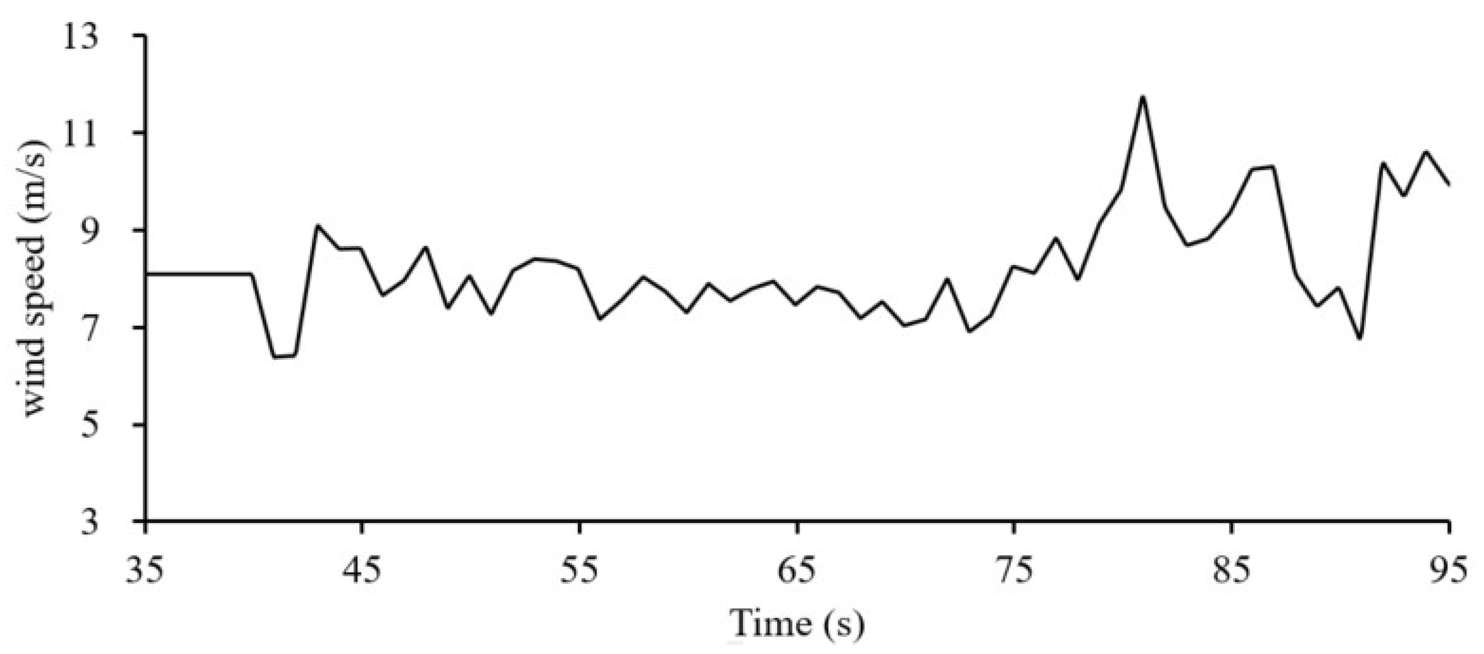
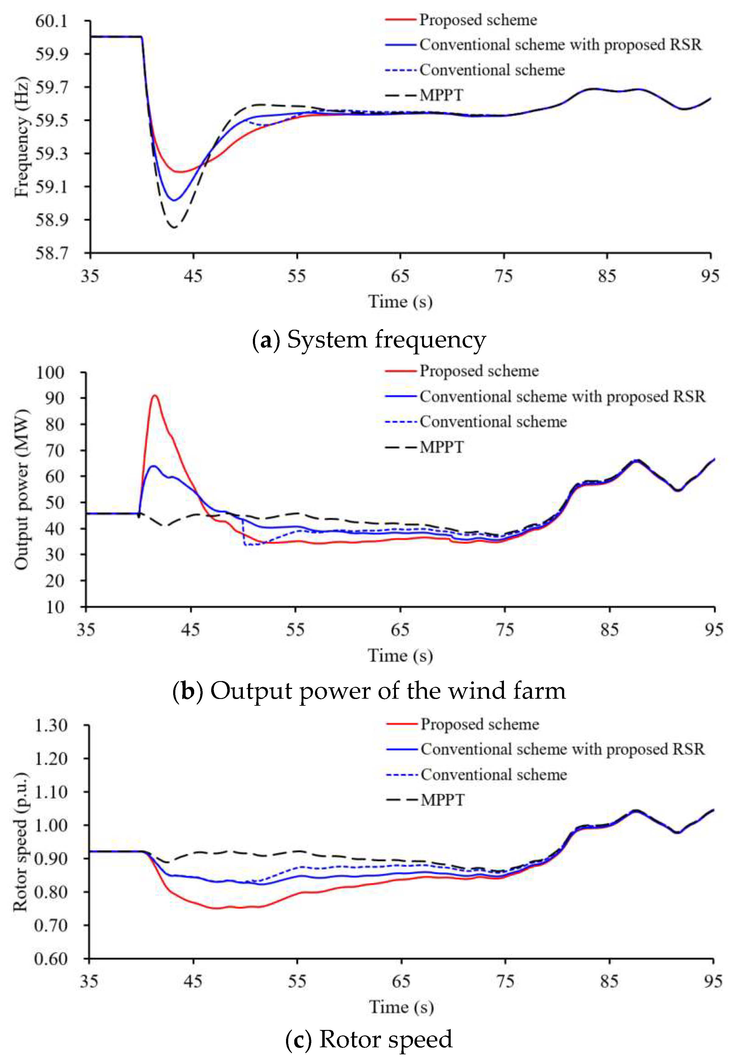
4.4. Case 4: Varying Wind Speed, Disturbance = 140 MW
Compared to Case 3, random wind speed conditions were employed instead of a fixed wind speed, as shown in
Figure 16. As a result, the frequency nadirs for the proposed IRI scheme and conventional IRI scheme were 59.187 Hz and 59.016 Hz, respectively, as indicated in the red line and blue lines. These were lower than those in Case 3 due to the decreasing wind speed conditions during the frequency disturbance. In the RSR period, the proposed RSR scheme could reduce the second frequency drop, as indicated in the red solid and blue solid lines in
Figure 17.
5. Discussion
In the proposed scheme, the proposed control coefficient for the inertial imitation period and control coefficient for rotor speed recovery were suggested to improve the frequency nadir and alleviate the negative effects of RSR on the system frequency. The capability during the IRI period and RSR period could be indicated in the simulation results.
As shown in the simulation results, the proposed IRI scheme could improve the frequency nadir since the control coefficient is related to the rotor speed and frequency deviations. As the rotor speed decreases, the control coefficient for the IRI period will decrease, weakening the capability of the improvement in the frequency nadir, as indicated in Case 1, Case 2, and Case 4. As the size of the disturbance increases, the control coefficient becomes greater to improve the frequency nadir, as indicated in Case 2 and Case 3. As shown in the results for the RSR period, the control coefficient, which was applied in the conventional scheme and proposed scheme, could effectively alleviate the negative effects of RSR on the system frequency. This is because the suggested coefficient gradually decreases. However, in the case of the conventional scheme without RSR, this would result in a large SSFD.
From the viewpoint of frequency nadir, the proposed scheme (red solid line) was better than that in the conventional scheme due to the higher frequency nadir. From the viewpoint of reducing the second frequency, both the proposed scheme (red solid line) and conventional scheme with the RSR scheme (blue solid line) could remove the second frequency drop.
The joint probability of the tripping of a synchronous generator is low. As the wind power penetration level increases, wind turbine generators will become the dominate frequency support devices. Therefore, a wind turbine with kinetic energy but without reserve power could participate in inertial response imitation to support the system frequency while effectively regaining the rotor speed without causing SSFD.
6. Conclusions
This paper proposes an innovative IRI and RSR control scheme to provide better frequency response and RSR service for an electric power grid. To this end, the coupling relationship between the control coefficient of the DFIGs and the frequency deviation was established by using the exponential function so that the control coefficient becomes large with the increasing frequency deviation. Then, an exponential function was employed to schedule the dynamic control coefficient of RSR to alleviate the negative effects of RSR on the system frequency.
The simulation studies clearly indicate that the proposed method can improve the system frequency stability more than that in the conventional schemes under the scenarios of various disturbances and wind speed conditions. As the disturbances and wind speeds became large, the improvement in the frequency nadir was obvious. Furthermore, the proposed adaptive control coefficient alleviates the negative effects of RSR on the system frequency.
The benefits of this study can be summarized as follows. (1) The control coefficient during the IRI period was defined as a function of rotor speed and frequency deviation based on the exponential function. The control coefficient became large with the increasing frequency in the deviations and rotor speed to improve the frequency nadir under various disturbance and wind conditions. (2) The exponential function was employed to schedule the dynamic control coefficient during the RSR period. The control coefficient will gradually decrease to avoid a reduction in the output power, thereby alleviating the size of the SSFD.


