1. Introduction
GaN-based Light-emitting diodes (GaN LEDs) demonstrate significant potential to replace traditional lighting sources. With a luminous efficacy of more than 220 lm/W, GaN LEDs have been regarded as the fourth generation of solid-state light sources, following incandescent, fluorescent, and high-intensity discharge lamps. Due to the advantages of high efficiency, small size, fast response, low power consumption and long life [
1,
2], GaN LEDs are widely utilized in commercial lighting, medical lighting, agricultural lighting, sports lighting, entertainment lighting, and other fields [
3,
4]. Nevertheless, these benefits attributed to GaN LED capabilities are achieved by the LED driver.
Conventional GaN LED driving systems with constant current are broadly classified into two competitive architectures, namely the switched-mode power supply (SMPS) [
5] and linear-mode driving [
6]. Typical SMPS LED driving circuit topologies, such as buck [
7], boost [
8], and buck-boost [
9], are characterized by high efficiency and low flicker with a bulky system and a comparatively higher cost. Linear LED driving circuit topologies primarily use linear constant-current regulators, avoiding complex structures, including voltage transformation, filtering, and voltage stabilization in SMPSs. This compact topology of linear LED driving contributes to fewer passive components, reduced electromagnetic interference (EMI), high reliability, long life, and low cost, as proven in single-phase AC power grids [
10,
11,
12].
However, the high pulsation of the single-phase AC rectified voltage makes it impossible to achieve a high power factor (PF) and flicker-free simultaneously, limiting the lighting applications of linear GaN LED driving in the high-end market. Commonly, general lighting is powered by single-phase AC power, and only for high-power lighting is three-phase AC power considered. Currently, there is no report of three-phase AC power being used to drive GaN LEDs in linear mode.
To save lighting costs and alleviate flicker, we turned the sight at the three-phase AC power and proposed a novel pulsating DC high-voltage linear driving scheme for GaN LED general lighting. This novel linear driving scheme with three-phase AC power can easily make up for the shortcomings of single-phase AC power, which is mainly reflected in three aspects:
- (1)
Three-phase power provides a higher rectified voltage than single-phase power and is adaptable to thinner cables, yielding a reduced wiring cost;
- (2)
The frequency of the three-phase AC rectified voltage with a diode-bridge full-wave rectifier is six times the fundamental frequency of the power grid and three times the frequency of the single-phase AC rectified voltage;
- (3)
The pulsating DC component of the three-phase AC rectifier voltage is significant (~90.7% of the effective voltage). The flicker problem can be effectively alleviated by the higher frequency and the significant DC component.
This scheme is well-suited for specific public and industrial general lighting applications such as tunnel lights, high bay lights, stadium spotlights, and floodlights, all of which are in hard-to-access locations with available three-phase AC power grids [
13].
In this paper, our efforts for the proposed scheme are mainly in two aspects: first, optimizing the GaN LED distribution of a linear multi-string LED driving scheme to balance GaN LED power and driving efficiency for the purpose of diminishing the effects of grid voltage fluctuations; and second, constructing and testing a modular prototype of a linear double-string GaN LED driving lighting system with three-phase AC power to verify the feasibility of the proposed scheme. In the end, the results confirm for the first time that the novel pulsating DC high-voltage linear drive scheme for GaN LEDs with three-phase AC power is capable of well solving the dilemma between PF and flicker of single-phase AC power while maintaining high reliability, small size, and low cost. The comparisons of single-phase and three-phase AC power sources for linear GaN LED driving are given in
Table 1.
The paper is organized as follows:
Section 1 clarifies the motivation and efforts for driving GaN LEDs linearly utilizing three-phase AC power with pulsating DC.
Section 2 describes the topology and the operating principles.
Section 3 calculates the LED power and driving efficiency of the multi-string GaN LED architecture to optimize the distribution of LEDs in sub-strings.
Section 4 presents the experimental results and discussion of the high-voltage linear double-string GaN LED driving prototype. Lastly, the conclusion is given in
Section 5.
2. Driving Principle
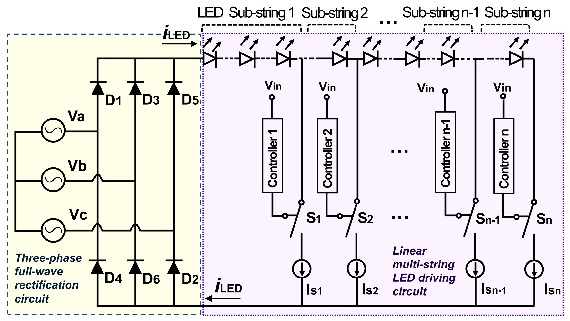
The equivalent circuit diagram of the novel pulsating DC high-voltage linear driving scheme for multi-string GaN LED is shown in
Figure 1. It is primarily composed of two modules: a three-phase full-wave rectification circuit and a linear multi-string GaN LED driving circuit without capacitors and inductors. The three-phase full-wave rectification circuit, which supplies a high pulsating DC voltage to loads, comprises a three-phase AC power supply and a set of rectifier diodes for AC/DC conversion.
The linear multi-string GaN LED driving circuit is built with LED sub-strings and a linear constant current regulator with multiple ports, which divides the high turn-on voltage of the LED string into the low turn-on voltage of each LED sub-string to reduce power loss and achieve high efficiency. Further, the current regulator typically contains metal oxide semiconductor field-effect transistors (MOSFETs), comparators, operational amplifiers, resistors, and other components [
6], where the current regulator can be equivalent to n controllable constant current sources
Is[k] (
k = 1, 2,
…,
n). The ends of n GaN LED sub-strings are connected individually with
Is[k] (
k = 1, 2,
…,
n), which are parallel with each other, sharing the negative electrode in the loop. The current of
Is[k] (
k =
1,
2,
…,
n) is given by
I[k] (
k = 1, 2,
…,
n). And the total voltage drop of the first
k GaN LED sub-strings is marked as
Vf[k] (
k = 1, 2,
…,
n). By analogy, the saturation voltages of the current regulator in the n branches can be represented independently by
Vsat[k] (
k = 1, 2, …,
n).
The three-phase AC voltage in power grids used to drive LEDs can be expressed separately as
where
U is the phase voltage.
Rectified voltage, i.e., the input voltage
Vin for LEDs, is
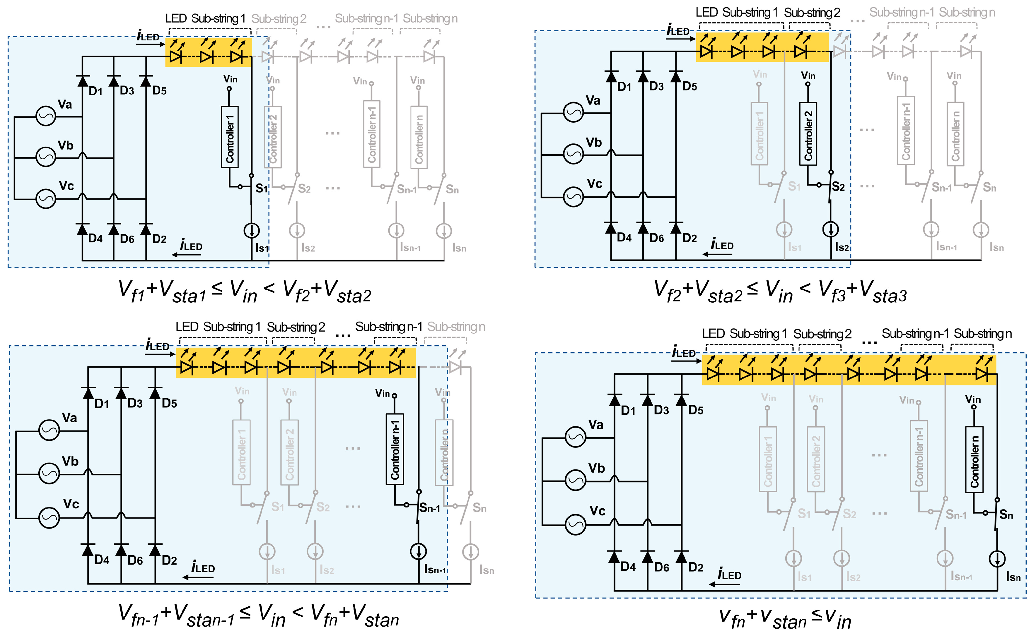
The specific operation of this circuit is illustrated in
Figure 2 and can be described as follows: the n constant current sources are turned on or off in sequence with the ripple of
Vin. If
Vf[k−1] + Vsat[k−1] ≤ Vin < Vf[k] + Vsat[k] (
k =
1,
2,
…,
n),
Is[k−1] (
k =
1,
2,
…,
n) will be turned on sequentially, and other constant current sources will be turned off; if
Vin ≥ Vfn + Vsatn,
Isn, will be turned on and if
Vin < Vfn + Vsatn,
Isn will be turned off. It is similar to the linear multi-string GaN LED driving principle for single-phase AC power in Ref. [
14].
In summary, the number of illuminated GaN LED sub-strings depends on the level of Vin; it is less at low Vin and grows as Vin increases. Also, the proportion of on-time for each sub-string depends on Vf[k] (k = 1, 2, …, n).
3. Calculation and Optimization
Grid voltage fluctuations have a significant effect on GaN LED lighting applications. Therefore, we optimized the GaN LED distribution in sub-strings by adjusting Vf[k] (k = 1, 2, ..., n) to reduce the impact of voltage fluctuations. In the process, multi-string GaN LED power PLED and driving efficiency η were calculated as two essential parameters. Their product was proposed as an optimization goal to balance high PLED and high η.
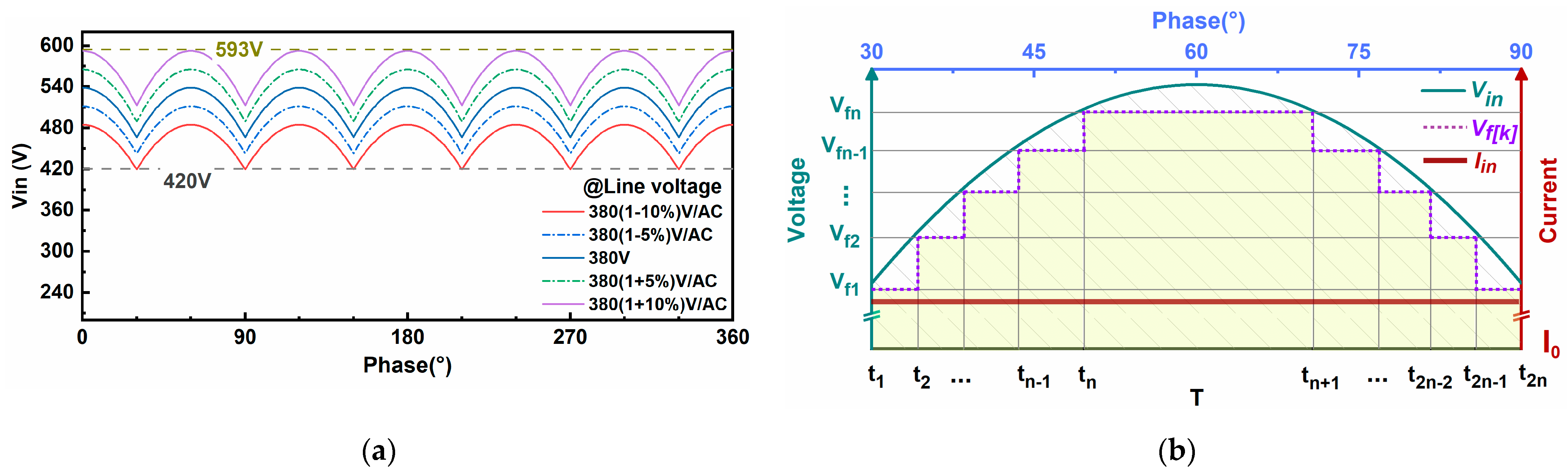
To illustrate the calculation process more clearly, this paper shows specific calculation examples with 380 V line voltage, and the input voltage
Vin was considered within a tolerance of ±10%. For 380 V ±10% line voltage, the corresponding
Vin range is 420–593 V, as shown in
Figure 3a.
3.1. LED Power and Driving Efficiency
For simplifying the calculation, suppose that the input constant current
Iin =
I[k] (
k = 1, 2,
…,
n) =
I0 and
Vsat[k] (
k = 1, 2,
…,
n) = 0 V (as
Vsat[k] is much smaller than
Vf[k], which can be ignored). To achieve the maximum driving efficiency and the lowest flicker, the optimum
Vf1 should be set at as same as the minimum,
Vin, so that the first GaN LED sub-string operates continuously without being affected by the
Vin ripple, i.e., the input current is constant at
I0, as shown in
Figure 3b. Then the input power
Pin can be calculated by
where
T is the period of
Vin, equal to 1/6 of the fundamental period of three-phase AC voltage.
Considering the symmetry of the
Vin waveform in the period, GaN LED power
PLED is
where
t[k] (
k = 1, 2,
…,
n) is the time when
Vin(
t) =
Vf[k] + Vsat[k] (
k = 1, 2,
…,
n) independently, which is also the time when
Is[k] (
k = 1, 2,
…,
n) is turned on in sequence, and
tn+1 is the time when
Isn is turned off.
Driving efficiency
η is defined as
η equals the ratio of the area under the stepped line representing
Vf[k] (
k = 1, 2,
…,
n) to the area under the arc line representing V
in in
Figure 3b. It is observed that the larger the number of GaN LED sub-strings, the closer the ratio is to 1.
However, the number of GaN LED sub-strings can’t be as large as possible in practice. On the one hand, the multi-string GaN LED structure reduces the utilization ratio of GaN LEDs, which increases the material cost of lamps; on the other hand, each MOSFET connected to the GaN LED sub-string must be capable of withstanding high voltage, so each port needs to use a high-voltage MOS device. Multiple high-voltage MOSFET devices will increase the size and cost of the current regulator chip. Therefore, there is a trade-off between the total luminous flux of GaN LEDs and the cost of multi-string GaN LEDs in lighting applications. Given the practical applications, only the optimization results and analysis of the double-string and triple-string GaN LED schemes were shown for reference.
3.2. Optimization for Double-String GaN LED
In the double-string GaN LED driving scheme, Vf1 is set to 420 V, i.e., the minimum value of Vin, to ensure that the first LED sub-string can be lit all the time. Vf2 is set to 420–564 V. I0 is set to 40 mA to be consistent with the experiment.
Figure 4a shows
PLED of the double-string LED with different
Vf2. At
Vf2 =
Vf1 = 420 V, it is equivalent to a single-string LED in the circuit, and there is almost no change in
PLED as the line voltage increases. At 420 V <
Vf2 < 492 V,
PLED increases with the rise of line voltage. At
Vf2 ≥ 492 V, a breakpoint can be seen in
PLED, and it shifts to the right as V
f2 increases. At this breakpoint, V
f2 equals
Max(
Vin). This means that when
Vf1 ≤ Max(
Vin)
< Vf2, only the first LED sub-string operates, and
PLED remains constant; when
Max(
Vin)
≥ Vf2, the second LED sub-string starts to work and
PLED increases with the increase of
Vin.
Figure 4b shows the
η of the double-string LED with different
Vf2 values. At 420 V ≤
Vf2 < 492 V,
η gradually decreases with the increase of line voltage. Similar to the trend of
PLED, the breakpoint also appears at
Vf2 ≥ 492 V. Overall,
PLED and
η are obviously impacted by line voltage fluctuations.
PLED remains stable with the decrease of
η at small
Vf2, while
PLED fluctuates significantly with the increase of
η at high
Vf2. Therefore, it isn’t easy to select
Vf2 intuitively.
Taking the balance of
PLED and
η into account, the maximum average value of
PLED ×
η within ±10% voltage fluctuations was selected as a candidate for optimizing
Vf2. The optimization goal
G in the double-string scheme can be expressed as
where
U is the input voltage
Vin and
U0 is the rated line voltage within ±10% tolerance.
G rises firstly and then falls as the line voltage increases, exhibiting a parabolic-like trend in
Figure 5a. Within ±10% voltage fluctuations, the maximum
G is achieved at optimal
Vf2 = 492 V, and the corresponding
η is 87% (@420V line voltage)–95% (@365V line voltage).
3.3. Optimization for Triple-String GaN LED
Similarly, in the triple-string GaN LED driving scheme, Vf1 is set to 420 V, and I0 is 40 mA. Vf3 is set to 420–564 V. Vf2 satisfies Vf1 < Vf2 < Vf3 and the optimal Vf2 is calculated after its corresponding Vf3 is determined.
The optimization goal
G in the triple-string GaN LED scheme is
Figure 5b shows the three-dimensional surface of
G with different
Vf2 and
Vf3. The maximum
G is calculated at
Vf2 = 477 V and
Vf3 = 522 V, and the corresponding calculated
η is 93% (@420V line voltage)–96% (@387V line voltage). A comparison of single-, double- and triple-string LED driving schemes reveals that
η increases with the number of GaN LED sub-strings.
4. Experiment and Discussion
A double-string GaN LED lighting system linearly driven by three-phase power with pulsating DC was constructed as a module prototype and tested for driving efficiency, harmonic current, and flicker, as shown in
Figure 6. Twenty-nine GaN LED lamps were mounted on the printed circuit board (PCB). The forward voltage of each GaN LED lamp used in the experiment is 18 V. For continuous operation of the first LED sub-string to alleviate flicker, the number of LED lamps in the first sub-string was chosen to be 23, corresponding to
Vf1 = 414 V, a little lower than the minimum input voltage of 420 V. The linear constant current regulator IC chip with dual-channel, named SM2186E, provided by Shenzhen Sunmoon Microelectronics Co., LTD [
15], was used to control the turn-on and turn-off of the double-string GaN LED with a constant current of 40 mA.
It’s worth noting that the total cost of components in the system, including six diodes, one regulator, and one resistor, is around $0.1. In addition, by connecting several such modules in parallel, it is feasible to assemble high-power lighting equipment while maintaining high driving efficiency and high PF.
At 380 V ± 10% line voltage, the first LED sub-string with 23 GaN LED lamps is in continuous operating mode, while the second LED sub-string with 1–6 GaN LED lamps is in discontinuous operating mode. Specifically, the distribution of GaN LED lamps in both sub-strings and their corresponding
Vf[k] (
k = 1, 2) can be seen in
Table 2.
In this experiment, the results of PLED and η in the double-string GaN LED were obtained by Keysight DSOX3024T oscilloscope. The effects of harmonic, PF and total harmonic distortion (THD) were tested by PF9830 digital power meter (Hangzhou Everfine Phtoto-E-Info Co., LTD). The flicker results were tested by a portable flicker-meter “Light master” (OPPLE Lighting Co., LTD). And the Light master was placed ~0.5 m above the central position of the light board to receive the flicker signal.
4.1. LED Power and Driving Efficiency
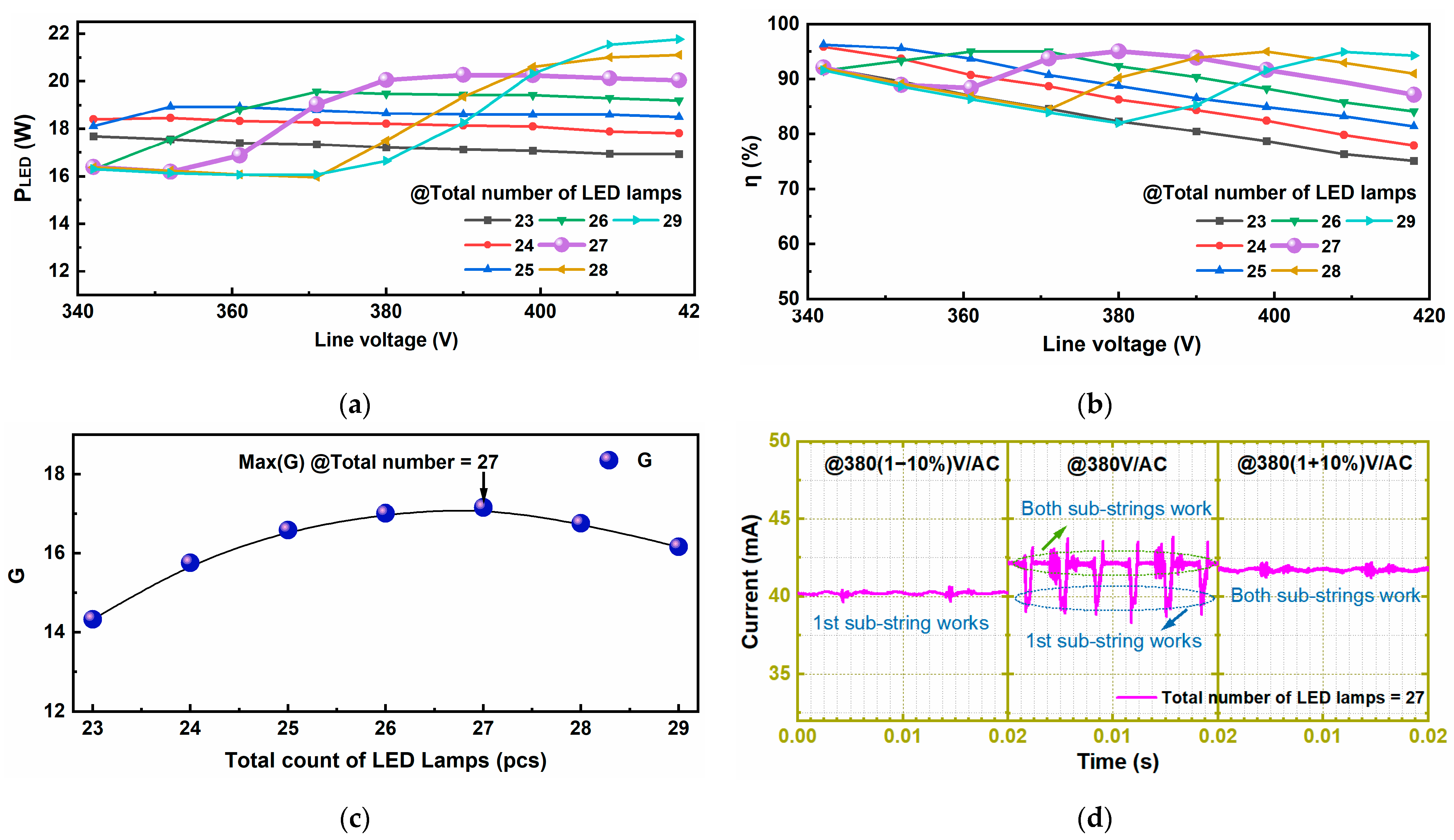
Figure 7a,b show the experimental results of
PLED and
η under 380 V ± 10% line voltage, respectively. The experimental results are essentially consistent with the calculations.
PLED of the module prototype is 16–22 W, corresponding to a very low driving cost of
$0.005/W. At 380 V line voltage, both
PLED and
η increase firstly and then decrease with the rise of the total number of GaN LED lamps and the maximum
η (~94%) is achieved when there are 23 GaN LED lamps in the first sub-string and 4 GaN LED lamps in the second sub-string.
Figure 7c shows the
G of the module prototype. The maximum
G is obtained when the total number of GaN LED lamps is 27 (23:4), and its corresponding
Vf1 = 414 V and
Vf2 = 486 V are closest to the calculation results. In addition,
Figure 7d shows the driving current of the module prototype with a total number of 27 GaN LED lamps at different line voltages. The driving current is measured to be 40 mA ± 4% within ±10% voltage fluctuations.
4.2. PF and THD
Figure 8a shows the voltage waveform
v(
t) and current waveform
i(
t) of each AC phase in the linear GaN LED driving scheme. Based on the voltage waveform
v(
t) and current waveform
i(
t), PF is calculated by its definition to be 0.955, and THD is calculated as 31% by the Fourier series on current waveform
i(
t) [
16]. Furthermore,
Figure 8b shows the PF and THD of the module prototype with a total number of 27 GaN LEDs under 380 V ± 10% line voltage. It can be seen that PF is maintained near 0.952 and THD is about 31%, meeting the requirement of ENERGY STAR [
17]. Experimental results agree with theoretical calculations in
Figure 8a.
4.3. Harmonic
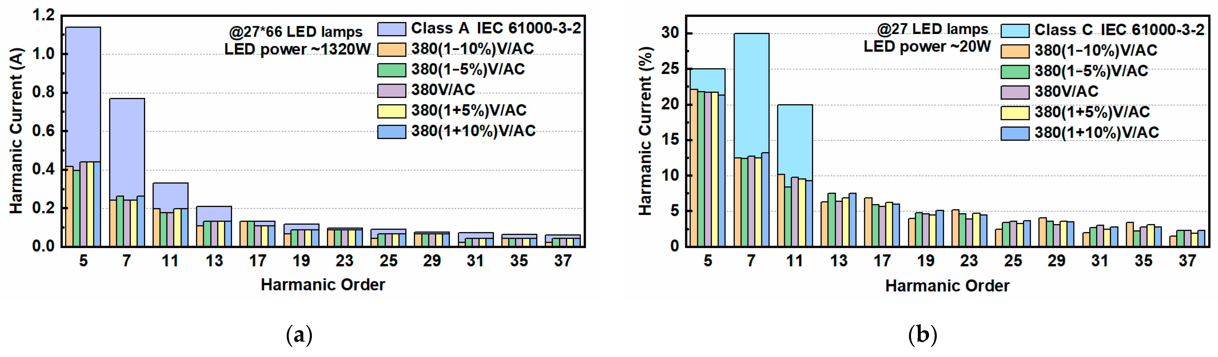
Three-phase GaN LED driving falls into the regulation for IEC 61000-3-2 Class A due to it being balanced three-phase equipment [
18]. The harmonic result indicates that only the (6
k ± 1)-th (
k = 1, 2,
…) harmonic currents exist, and all harmonic currents at 20 W GaN LED power fully satisfy the requirements of Class A.
Figure 9a shows the harmonic currents of 66 module prototypes connected in parallel with a power of ~1320 W, its corresponding harmonic currents meet the Class A requirements.
On the other side, GaN LEDs are also lighting equipment, limited by the most restrictive regulation for IEC 61000-3-2 Class C.
Figure 9b shows the corresponding harmonic currents expressed as a percentage of the fundamental current under 380 V ± 10% line voltage. The harmonic currents at 20 W GaN LED power also meet the requirements of Class C because when the rated power < 25 W, Class C only limits the fifth, seventh, and 11th harmonic currents. However, when the rated power > 25 W, e.g., 66 module prototypes connected in parallel, its 5th–37th harmonic current will exceed the Class C requirement.
For high-power lighting equipment, one optimal solution was considered to meet Class C, in which a centralized high-power three-phase full-wave rectifier was used to produce pulsating DC power. As shown in
Figure 10, many pieces of lighting equipment are installed along electric lines. Both lines flow constant current. There are no problems with electromagnetic interference (EMI) along these lines. And the hybrid active power filter (HAPF) is assembled for centralized harmonic suppression in the busbar [
19]. Compared with the common solution that each GaN LED driving topology includes electromagnetic compatibility, rectification, power factor correction, filtering, inverter step-down, voltage stabilization, etc., this optimal solution with fewer driving components and higher reliability is more suitable for road and tunnel lighting projects with harsh environmental conditions.
4.4. Flicker
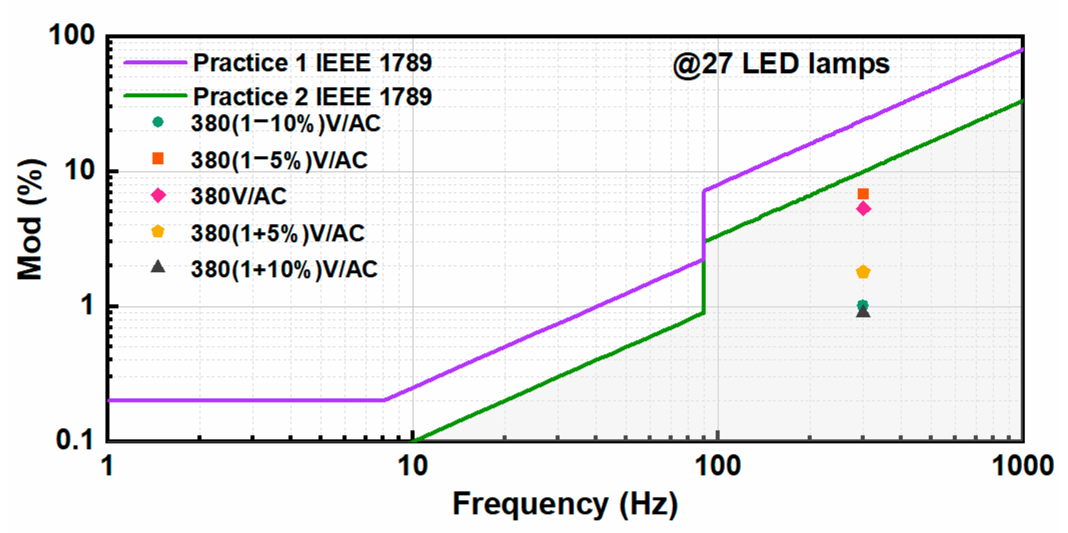
To limit the harmful effects of flicker in lighting applications, such as headaches, migraines, or any other neurological response, IEEE Standard 1789-2015 is recommended for evaluating flicker in general illumination [
20]. Flicker, also described as modulation (%), is relevant to the ripple of the luminance waveform. Following its definition in Ref. [
21], the theoretical modulation can be calculated. For the optimized GaN LED sub-strings (23:4), the maximum luminance equals the luminance sum of 27 GaN LED lamps and the minimum luminance equals the luminance sum of 23 GaN LED lamps. Therefore, the estimated maximum modulation is 8% at 300 Hz.
Figure 11 shows the measured modulation of 27 GaN LED lamps under 380 V ± 10% line voltage and assesses the modulation results according to the most restrictive practice 2 in IEEE Standard 1789-2015. All results are within the recommended region. The maximum modulation was measured to be about 8% at 380 V line voltage, consistent with expectation.
5. Conclusions
The paper investigates a novel pulsating DC high-voltage linear driving scheme for GaN LED general lighting. It combines a three-phase full-wave rectification circuit with a linear multi-string GaN LED driving circuit. A double-string GaN LED lighting system linearly driven by three-phase power was constructed as a module prototype to verify its superiority and practicality. The experimental results show high η, high PF, and flicker-free. Further, the calculation results demonstrate that η can be improved with the optimization of GaN LED distributions and the increase of LED sub-string numbers. This scheme, which covers excellent driving performance, high reliability, and low cost, shows great competitiveness for general lighting in the future, especially in public and industrial lighting applications.
This is only the first step towards high-voltage linear driving by pulsating DC for GaN LEDs. People may find many research works that need to be fulfilled, such as the current regulator IC should be redesigned to keep constant power driven by three-phase AC power; fresh LED lighting sources should be developed to avoid the perspective luminance changes of high-end LED strings when input voltage fluctuates; and customized smart/wireless controllers powered by pulsating DC voltage are needed to adjust the brightness of the LED lamps intelligently, etc.
Author Contributions
Conceptualization, Y.C. and X.Z.; methodology X.Z. and S.L.; investigation, X.Z.; writing—original draft, X.Z.; writing—review and editing, Y.C., K.F. and X.Z.; supervision Y.C.; project administration, B.W., R.Y. and H.G. All authors have read and agreed to the published version of the manuscript.
Funding
This research received no external funding.
Data Availability Statement
The data that support the findings are available from the corresponding author upon reasonable request.
Acknowledgments
Thanks to Vacuum Interconnected Nanotech Workstation (Nano-X), Chinese Academy of Sciences (CAS), for supporting the test.
Conflicts of Interest
The authors declare no conflict of interest.
References
- Yan, J.; Jia, B.; Wang, Y. Monolithically integrated voltage-controlled MOSFET-LED device based on a GaN-on-silicon LED epitaxial wafer. Opt. Lett. 2021, 46, 745–748. [Google Scholar] [CrossRef] [PubMed]
- Fan, X.; Guo, W.; Sun, J. Reliability of high-voltage GaN-based light-emitting diodes. IEEE Trans. Device Mater. Reliab. 2019, 19, 402–408. [Google Scholar] [CrossRef]
- Huang, J.; Hu, Z.; Gao, X.; Xu, Y.; Wang, L. Unidirectional-emitting GaN-based micro-LED for 3D display. Opt. Lett. 2021, 46, 3476–3479. [Google Scholar] [CrossRef] [PubMed]
- Dalapria, V.; Marcos, R.L.; Bussadori, S.K.; Anselmo, G. LED photobiomodulation therapy combined with biomaterial as a scaffold promotes better bone quality in the dental alveolus in an experimental extraction model. Lasers Med. Sci. 2022, 37, 1583–1592. [Google Scholar] [CrossRef] [PubMed]
- Teixeira, L.; Loose, F.; Alonso, J.M. Pre-emphasis control in switched-mode power converter for energy-efficient wide bandwidth visible light communication. IEEE J. Emerg. Sel. Top. Power Electron. 2021, 9, 146–155. [Google Scholar] [CrossRef]
- Lyu, X.; Ren, N.; Cao, D. Optimal configuration of high-efficiency segmented linear LED driver with genetic algorithm. IEEE J. Emerg. Sel. Top. Power Electron. 2019, 7, 209–215. [Google Scholar] [CrossRef]
- Kircher, D.; Pommerenke, D.J. EMC Analysis of the Inverting Boost/Buck Converter Topology. Electronics 2022, 11, 3388. [Google Scholar] [CrossRef]
- Li, T.; Gan, Y. Hybrid Modulated DCDC Boost Converter for Wearable Devices. Electronics 2022, 11, 3418. [Google Scholar] [CrossRef]
- Hsieh, Y.C.; Cheng, H.L. A soft-switching interleaved buck–boost LED driver with coupled inductor. IEEE Trans. Power Electron. 2022, 37, 577–587. [Google Scholar] [CrossRef]
- Noge, Y.; Fuse, H.; Shimizu, T. Experimental validation of linear AC LED driver with quantitative design method. In Proceedings of the 2017 IEEE Applied Power Electronics Conference and Exposition (APEC), Tampa, FL, USA, 26–30 March 2017; pp. 1484–1491. [Google Scholar]
- Sun, F.; Wang, Y.; Xie, J.; Dou, Q. Research on thermal performance of AC-LED light engine driven by segmented linear constant current driver. In Proceedings of the 2017 IEEE 3rd Information Technology and Mechatronics Engineering Conference (ITOEC), Chongqing, China, 3–5 October 2017; pp. 220–225. [Google Scholar]
- Jao, C.N.; Huang, L.J.; Hsia, C. Dimmable flicker-free linear LED driver. In Proceedings of the 2020 IEEE International Conference on Consumer Electronics—Taiwan (ICCE-Taiwan), Taoyuan, Taiwan, 28–30 September 2020; pp. 1–2. [Google Scholar]
- Castro, I.; Vazquez, A.; Lamar, D.G.; Arias, M.; Hernando, M.M.; Sebastian, J. An electrolytic capacitorless modular three-phase AC-DC LED driver based on summing the light output of each phase. IEEE J. Emerg. Sel. Top. Power Electron. 2019, 7, 2255–2270. [Google Scholar] [CrossRef] [Green Version]
- Liu, C.; Lai, X.Q.; He, H.S.; Du, H.X. Sectional linear LED driver for optimised efficiency in lighting applications. IET Power Electron. 2016, 9, 825–834. [Google Scholar] [CrossRef]
- Available online: http://www.chinaasic.com/chipDetails/detail_194.html (accessed on 22 October 2021).
- Erickson, R.W. Fundamentals of Power Electronics, 2nd ed.; Kluwer Academic Publishers: Secaucus, NJ, USA, 2000; pp. 596–616. [Google Scholar]
- ENERGY STAR Program Requirements Product Specification for Lamps (Light Bulbs)—Eligibility Criteria, V. 2.0; ENERGY STAR: Washington, DC, USA, 2016.
- Electromagnetic Compatibility (EMC)—Part 3-2: Limits—Limits for Harmonic Current Emissions (Equipment Input Current ≤ 16 A per Phase). IEC 61000-3-2:2018. Available online: https://webstore.iec.ch/publication/28164 (accessed on 5 October 2022).
- Herman, L.; Papic, I.; Blazic, B. A proportional-resonant current controller for selective harmonic compensation in a hybrid active power filter. IEEE Trans Power Deliv. 2014, 29, 2055–2065. [Google Scholar] [CrossRef]
- Lehman, B.; Wilkins, A.J. Designing to mitigate effects of flicker in LED lighting: Reducing risks to health and safety. IEEE Power Electron. Mag. 2014, 1, 18–26. [Google Scholar] [CrossRef]
- IEEE Std 1789-2015; IEEE Recommended Practices for Modulating Current in High-Brightness LEDs for Mitigating Health Risks to Viewers. IEEE: Manhattan, NY, USA, 2015. Available online: https://ieeexplore.ieee.org/document/7118618 (accessed on 16 October 2021).
| Disclaimer/Publisher’s Note: The statements, opinions and data contained in all publications are solely those of the individual author(s) and contributor(s) and not of MDPI and/or the editor(s). MDPI and/or the editor(s) disclaim responsibility for any injury to people or property resulting from any ideas, methods, instructions or products referred to in the content. |
© 2023 by the authors. Licensee MDPI, Basel, Switzerland. This article is an open access article distributed under the terms and conditions of the Creative Commons Attribution (CC BY) license (https://creativecommons.org/licenses/by/4.0/).


 ,
, 


