Article

Influence of Bulk Doping and Halos on the TID Response of I/O and Core 150 nm nMOSFETs

1
Department of Information Engineering, University of Padova, 35131 Padova, Italy
2
Department of Physics and Astronomy, University of Padova, 35131 Padova, Italy
3
LFoundry s.r.l., 67051 Avezzano, Italy
*
Author to whom correspondence should be addressed.
Electronics 2023, 12(3), 543; https://doi.org/10.3390/electronics12030543
Submission received: 30 November 2022 / Revised: 27 December 2022 / Accepted: 29 December 2022 / Published: 20 January 2023
(This article belongs to the Special Issue Radiation Tolerant Electronics, Volume III)

Abstract

:
The total ionizing dose sensitivity of planar 150 nm CMOS technology is evaluated by measuring the DC responses of nMOSFETs at several irradiation steps up to 125 krad(SiO2). Different TID sensitivities are measured for transistors built with different channel dimensions and operating voltages (I/O and core). The experimental results evidence strong relations between TID sensitivity and the doping profiles in the channel. I/O transistors have the highest TID sensitivity due to their thicker gate oxide and lower bulk doping compared with core devices. In general, narrow-channel devices have the worst degradation with negative threshold voltage shifts, transconductance variations and increased subthreshold leakage currents, suggesting charge trapping in shallow trench isolation (STI). The enhanced TID tolerance of short-channel core devices is most likely related to the increased channel doping induced by the overlapping of halo implantations. Finally, transistors fabricated for low-leakage applications exhibit near insensitivity to TID due to higher bulk doping used during the fabrication to minimize the drain-to-source leakage current.

1. Introduction

In space applications, integrated circuits (ICs) must overcome environmental hazards and at the same time keep their electric performance within the operational specification requirements [1]. Even if commercial devices are available in nodes lower than 5 nm, space systems require mixed signal electronics working with more consolidated technologies, such as the 150 nm CMOS node studied in this work [2]. Indeed, most modern CMOS technologies do not allow interfacing electronics with the standard of 3.3 V, which is still used in space applications. Furthermore, with the current semiconductor supply crisis, fabrication processes that are less stringent but more easily accessible are of interest when the performance requirements are not too high.
Ionizing radiation can affect the reliability of ICs by causing parametric shifts in transistor characteristics [3,4,5]. Trapped charges in the gate oxide of MOSFETs induce threshold voltage shifts, transconductance degradation and drive current variations [5]. In the last years, the shrinking of the gate oxide thickness of MOSFET technologies and new layouts with enhanced gate control, such as the FinFET and Gate-All-Around FET, have improved TID sensitivity [6,7,8,9,10]. Indeed, the buildup of a positive trapped charge scales with the dielectric thickness [3,4,5] also as a result of the increased probability of charge neutralization through the tunneling of electrons injected from adjacent semiconductor materials [11,12,13]. However, the downscaling of devices has brought new degradation mechanisms related to thick isolation oxides [5,14].
Several recent works about the TID effects of devices designed in the 180 nm MOSFET [15,16], 65 nm MOSFET [16], 28 nm MOSFET [7], 16 nm FinFETs [17,18] and other channel materials [19,20,21] show strong radiation-induced degradation related to charge buildup in Shallow Trench Isolation (STI) oxide and its interface. The worst degradation is found in narrow-channel transistors [15,16], an effect known as the Radiation-Induced Narrow-Channel Effect (RINCE) [16]. RINCE induces large parametric drifts in narrow MOSFETs [15,16,17,18], with leakage current increases due to the activation of parasitic transistors in n-channel MOSFETs [22,23,24,25]. Another TID-related issue becoming important for modern transistors is the degradation of spacer oxides and of the overlying silicon nitride layers above Lightly Doped Drain (LDD) extensions [26,27,28]. Furthermore, recent studies [18,29] have demonstrated that the TID responses of 90 nm, 28 nm and 16 nm CMOS technologies have started to be influenced by halo implantations, which can deeply change the channel doping [29,30,31,32,33]. In [29], experimental measurements and TCAD simulations revealed the important role of halo implantations, which can enhance TID tolerance due to the increase in the overall bulk doping in short-channel devices [29]. Following works on 16 nm FinFETs showed similar improvements in the TID tolerance of short-channel devices, underlining the important role of halo implantations for the TID response of the devices [18,29].
In this work, irradiated nMOSFETs designed in 150 nm Si planar MOS technology are characterized by DC static measurements, evidencing TID sensitivities depending on transistor type and channel dimension with trends that differ from previous studies on 130 nm and 150 nm technologies. I/O transistors exhibit worse TID-induced degradation compared to core devices, and devices designed with short channels have enhanced TID tolerance. The experimental results evidence the important role of channel doping in the TID sensitivity of devices, which may be different between devices of the same technological node due to changes in the doping profiles of halo implantations and of bulk wells. The results provide guidelines for IC designers to facilitate circuit qualification, as these geometry dependencies can be used as a mitigation strategy, especially in analog parts, where the area requirements are typically relaxed.

2. Devices and Experiments

2.1. Test Structures

The devices under testing were fabricated in the Mixed-Signal 150 nm CMOS Process (LF15A) from LFoundry, Italy. This work focuses on n-channel MOSFETs, which are provided on Si wafers in a customized array structure, containing several types and several geometries of transistors with no ESD protections.
As shown in Table 1, four types of transistors were tested: I/O 5V, I/O 3.3V, core HS 1.8V (High Speed) and core LL 1.8V (Low Leakage). Gate oxide was fabricated in SiO2 with an oxide thickness of <3 nm for 1.8 V devices. Compared with the 1.8 V transistors, the gate oxide thickness of 3.3 I/O devices was ~2.5×, and that of 5V I/O devices was ~6×. Moreover, the HS and LL devices had different doping profiles, which resulted in a lower threshold voltages for the HS type, as is discussed in Section 3.1.
Each array structure contained 12 different combinations of channel widths (0.32 μm < W < 10 μm) and channel lengths (0.15 μm < L < 10 μm). In this work, we focused the analysis on nMOSFETs with three significant channel dimensions (see Table 1): narrow and short, narrow and long, and large and long. Transistors of the same type shared gate, source and bulk terminals, whereas separated drain terminals were dedicated to each transistor. Transistors were measured on wafers through a manual probe station.

2.2. Exposure Conditions and Measurement Details

The devices under testing were irradiated up to 125 krad(SiO2) through irradiation steps of 25 krad(SiO2) at room temperature (RT) at the University of Padova, Italy, using an X-ray irradiator composed of a tungsten tube with a peak energy deposition of 10 keV [34]. The dose rate was set to 36 krad(SiO2)/hour within the ESCC 22900 standard rate [35], for a total exposure time of about 4 h. The X-ray spectra emitted from the tube was filtered with 150 μm Al foil in order to remove the low-energy spectra component (<8 keV). The devices under testing were biased and measured with the help of a wafer prober inside the irradiation cabinet. After exposure, annealing tests were performed, but, due to the constraints of wafer-level measurements, the annealing time was shortened with respect to the ESCC 22900 standard durations used with packaged devices [35]. The devices were first annealed at room temperature for 24 h and were then annealed for another 24 h at 100 °C by using a thermal chuck. According to previous studies [3,4,5,36,37,38,39], worst-case DC bias conditions were applied during irradiation and post-exposure annealing with the “ON” bias configuration (Vgs = Vdd and Vds = 0 V). At least two different devices of each type were evaluated for all experimental conditions with typical results, as shown below. The DC responses of the transistors were evaluated by measuring the main DC parameters with a semiconductor parameter analyzer (HP 4156) before exposure at several irradiation steps and after the annealing tests.

3. Experimental Results and Discussion
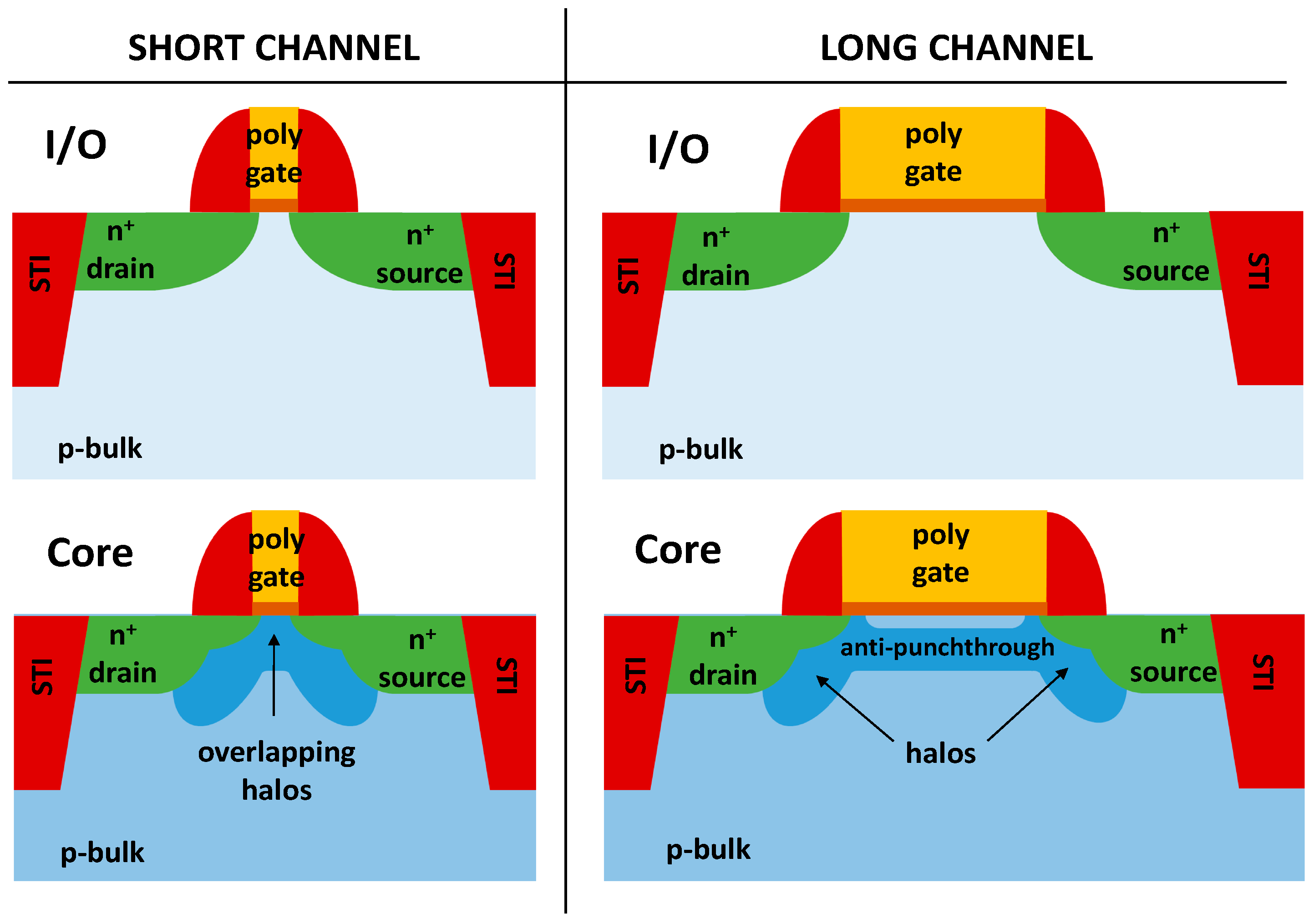
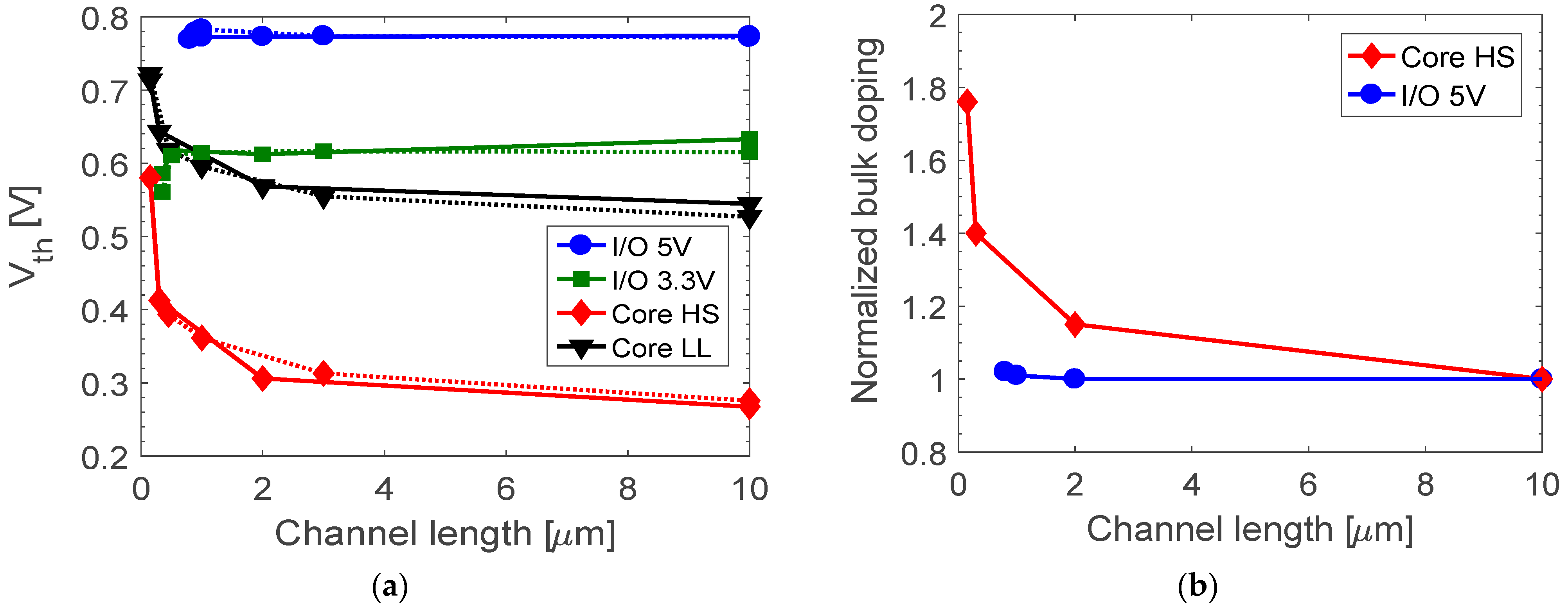
3.1. Bulk Doping

The I/O and core 150 nm nMOSFET structures are represented schematically in Figure 1. I/O devices are produced with a typical fabrication process for planar CMOS technologies with SiO2 gate oxide and STI oxides. Core transistors are designed with an additional anti-punchthrough implantation and source/drain halos. The anti-punchthrough implantation is a highly doped region, which is implanted a few nanometers under the gate oxide along the entire channel length. In n-channel MOSFETs, the halos are highly p-doped bulk regions localized close to the source and the drain extensions [39,40,41,42]. Both the anti-punchthrough implantation and halos are introduced into the core transistors to overcome Short-Channel Effects (SCEs), such as threshold voltage roll-off and high leakage currents.
As a result, in core devices, bulk doping along the channel is not uniform due to halo implantations, and the average doping concentration depends on the channel length. In short-channel transistors, the drain halo implantation can overlap with the source one [40,42], causing an increase in the doping in the center of the channel, which increases the threshold voltage of the short transistors [33,40,42]. The rise in the threshold voltage with decreasing channel length is called the Reverse Short-Channel Effect (RSCE) [33,42] and is typical of scaled CMOS technologies with high halo doping concentrations.
Figure 2a shows the threshold voltage Vth of pristine nMOSFETs. Vth is plotted as a function of the channel length for transistors with a channel width of 0.3 μm (continuous) and 10 μm (dotted). The Vth of I/O devices is insensitive to the channel length, as the bulk doping is uniform with the channel length (no halos). On the contrary, the trend of Vth-L of core devices is strongly characterized by the RSCE, indicating highly doped halo implantations, which increase overall channel doping.
Figure 2b highlights the channel length dependence of the bulk doping, which is retrieved at the center of the channel and 2 nm under the gate oxide. The value of the bulk doping of each transistor is normalized by the bulk doping of the longest channel transistor (L = 10 mm) of the same type. In core devices, the bulk doping increases by about 1.8× in the shortest channel length due to the overlap of halo implantations, which is consistent with the increase in the Vth shown in Figure 2. On the contrary, different I/O transistors have similar Vth regardless of the channel length.
Finally, the doping channel profiles of core LL devices are higher than the bulk doping of core HS devices. Indeed, LL transistors require increased bulk/halo doping to improve the leakage current at the expense of speed, which, on the contrary, are essential parameters in HS devices. The increased bulk/halo of LL devices is evident by comparing the values of subthreshold leakage current and the threshold voltage of LL and HS devices having the same channel dimension. Considering the LL and HS transistors with W/L = 10/10 μm, the subthreshold leakage current of the LL device is in the order of 10−14 A vs. 10−11 of the core HS device, and Vth is 0.55 V for the LL device vs. 0.25 V for the core HS device. Therefore, the transistors are characterized by different channel doping, depending on the transistor type and on the channel length.

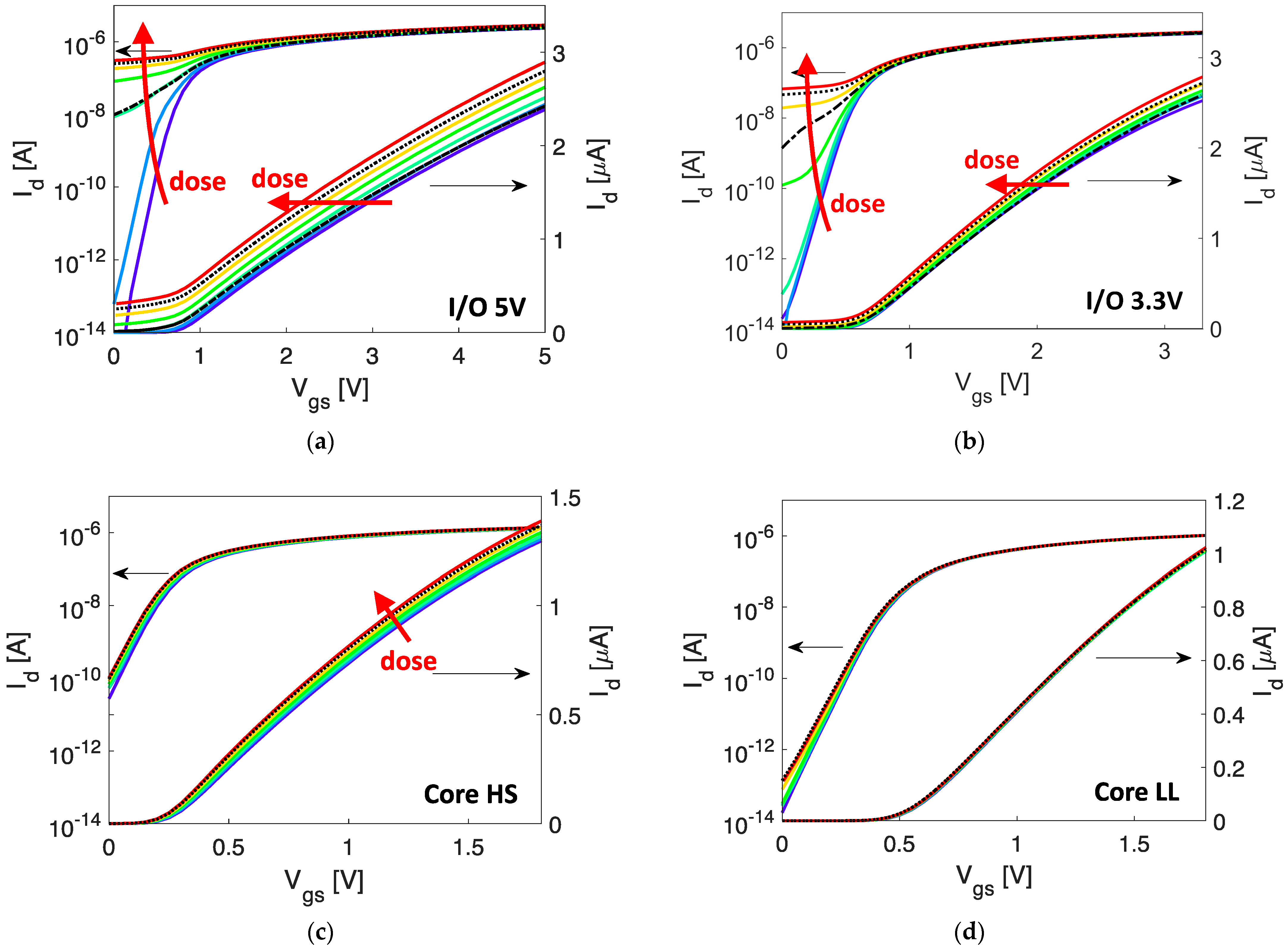
3.2. TID Effects on I/O and Core nMOSFETs

Figure 3 reports the Id-Vgs in logarithmic and in linear scales for I/O and core nMOSFETs with narrow and long channel dimensions, as shown in Table 1. Transistors are measured in the linear region (Vds = 0.1 V) at several irradiation steps up to 125 krad(SiO2). The TID responses of I/O devices (a and b) degrade more than the core transistors (c and d). The increased subthreshold leakage current suggests charge trapping in the STI oxides, and the negative shift of the threshold voltage suggests positive charge generation in the gate oxide. At 125 krad(SiO2), the transistor responses of I/O devices are dominated by a high leakage current, which degrades the Ion/Ioff ratio from ~108 to ~10. The Ion-lin current, defined as the drain-to-source current at Vgs = Vdd and Vds = 0.1 V, increases by 28% in the 5V I/O devices and by 12% in the 3.3 V I/O ones. After exposure, transistors are annealed for 24 h at room temperature and for 24 h at 100 °C. Room temperature annealing causes negligible effects, whereas high-temperature annealing induces large recovery of Ioff and an almost complete recovery of Vth, indicating the partial neutralization of the radiation-induced charge trapped in the gate oxide and STI.
Core devices are the most tolerant, with a negligible increase in the subthreshold leakage current, from 3 × 10⁻¹¹ A pre-rad to 10−10 A after 125 krad(SiO2) in HS core devices. Low leakage core devices are almost insensitive to TID with a variation in the Ion-lin current of smaller than 2% after 125 krad(SiO2). On the other hand, the TID response of HS core devices shows an evident increase in the transconductance with a cumulated dose and a negligible shift in the threshold voltage of less than 40 mV after 125 krad(SiO2). The insensitivity of Vth suggests negligible effects related to charge trapping in the gate oxide. A slight recovery is visible after the annealing test at room temperature.
Figure 4 compares the TID sensitivity of the four different types of MOSFETs: I/O 5V, I/O 3.3V, core HS 1.8V and core LL 1.8V. The variation in the main DC parameters—Ion-lin, Vth, gm and Ioff—are plotted as a function of the dose in narrow and long-channel transistors (W/L = 0.8/10 mm for I/O devices and W/L = 0.32/10 mm for core devices). The worst-case response is found in I/O 5V transistors, and the core LL transistors exhibit the best TID tolerance. The I/O 5V transistor shows a ΔVth shift of −0.6 V vs. −0.1 V for I/O 3.3V and <−0.05 V for core transistors. Room temperature annealing causes only marginal parametric shifts, whereas high-temperature annealing induces a large recovery of Vth for I/O 5V and I/O 3.3V.
Figure 4d shows the degradation of the subthreshold leakage current (Ioff), which is defined as the drain current at Vgs = 0 V and Vds = 0.1 V. When transistors are exposed to ionizing radiation, I/O transistors exhibit the largest increase in the Ioff with the worst-case in the 5V nMOSFETs with Ioff increasing from 8 × 10⁻¹⁵ A to 3.2 × 10⁻⁷ A. The leakage current of the I/O n-channel transistors exposed to TID flows from the drain to the source. This suggests TID-induced effects related to charge trapping in the STI, which may activate the parasitic channel close to the STI sidewalls [22,23,24,25]. On the contrary, LL and HS core nMOSFETs show modest increases in the leakage current with an increment of less than one order of magnitude after 125 krad(SiO2). After the irradiation, the room temperature annealing has very minor effects on the leakage current, with Ioff values of 2.6 × 10⁻⁷ A vs. 3.2 × 10⁻⁷ A before annealing. The following 100°C annealing for 24 h induces visible Ioff recoveries of about two orders of magnitude in 5V I/O transistors. However, the recovery of Ioff is partial if compared to the almost complete recovery of Ion, shown in Figure 4a, suggesting effects related to charge trapping in different locations of the STI, as is discussed in Section 4.
It is worth noting that the degradation mechanism in I/O devices and core devices is different. In I/O devices, the variation in the Ion current is caused first by a huge shift in Vth and secondly by the degradation of gm. On the other hand, the relatively small Ion variation in HS core devices is mostly related to a decrease in gm, as Vth is almost insensitive to TID effects. After 125 krad(SiO2), ΔIon is 10%, and Δgm is 10%.
In conclusion, by comparing the TID response of I/O 5V, I/O 3.3V, core HS and core LL, the main visible effects are as follows:
-
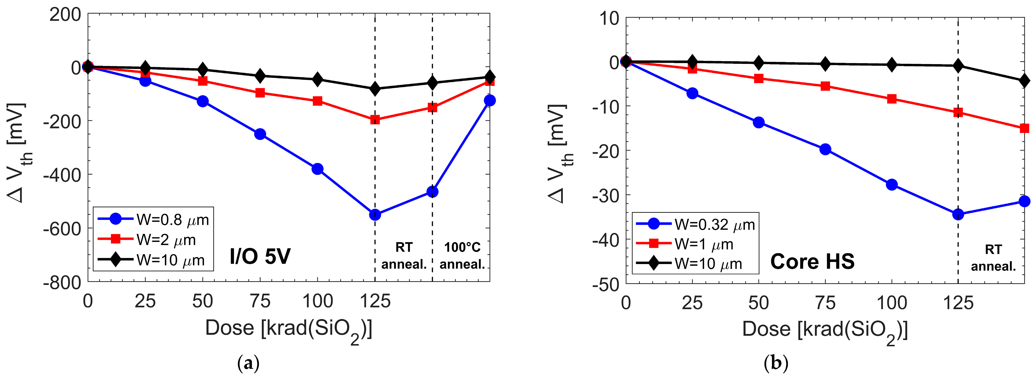
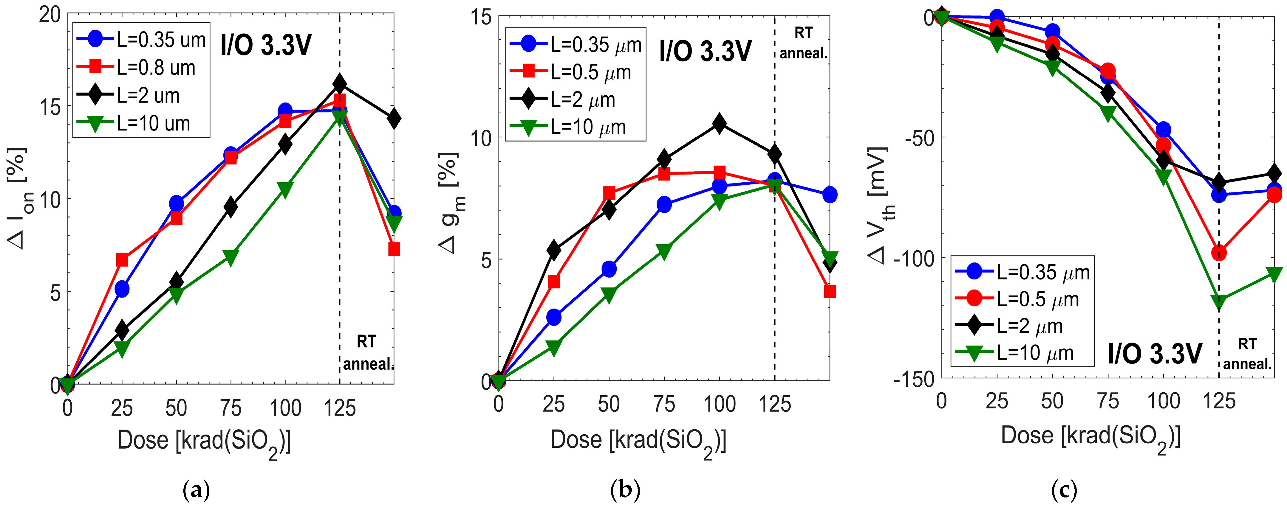
I/O transistors degrade more than core devices, mainly due to a large negative Vth shift and an increase in the subthreshold leakage current Ioff.
-
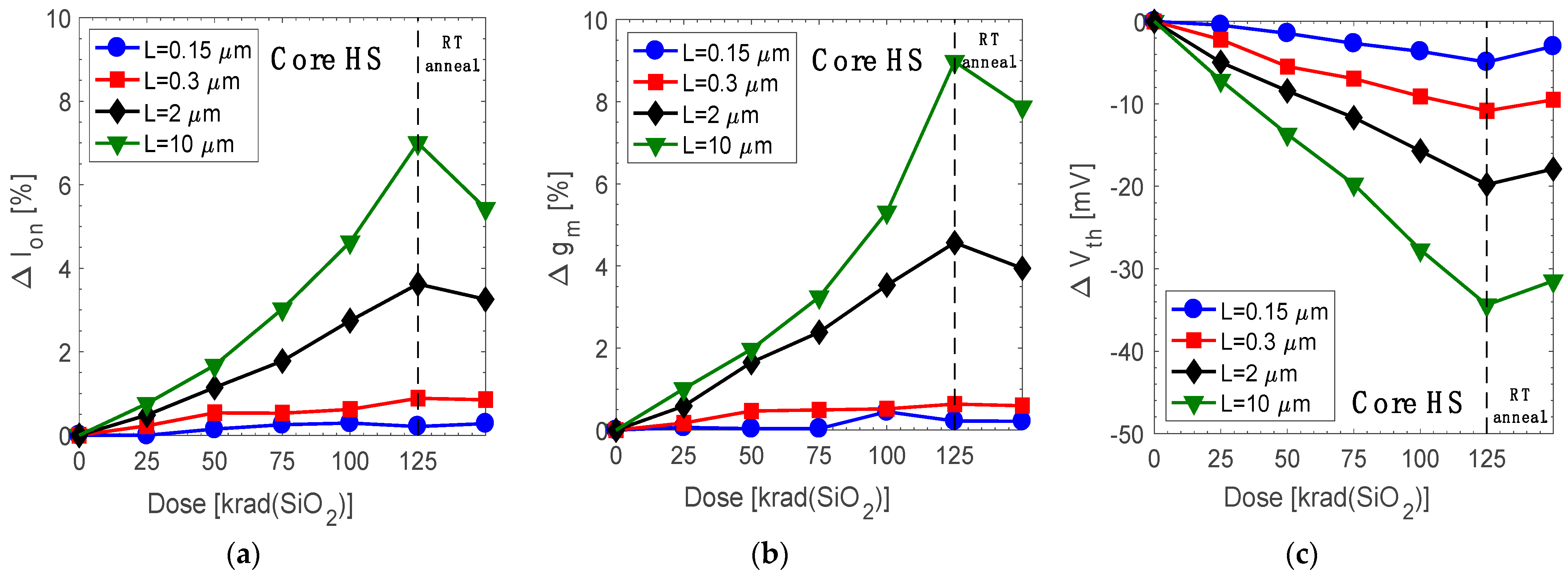
The TID degradation of core devices is modest and related to variations in gm.
-
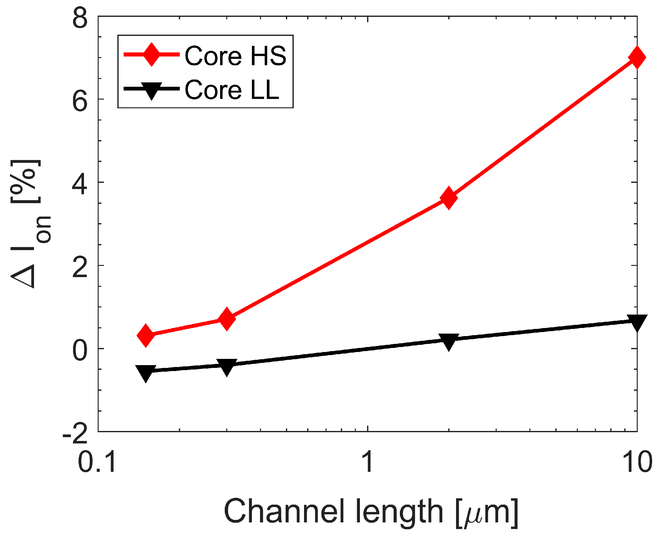
Low-leakage (LL) core devices show a higher TID tolerance than that of high-speed (HS) core devices.

3.3. Channel-Width-Dependent Effects

Figure 5 compares the Vth shift of several transistors with different channel widths and the same channel length (L = 10 μm). In both I/O and core devices, the worst-case response is found in narrow channel transistors, evidencing a clear channel-width-dependent effect. After 125 krad(SiO2), the Vth shift of the narrow I/O 5V nMOSFET (blue curve) is −600 mV, whereas the largest nMOSFET (black curve) is −35 mV. The negative variation in Vth in the transistor is induced by the large increase in the leakage current visible in Figure 4 and partially by the charge trapping in the gate oxide. The negligible variation in gm in the largest device, Δgm < 2% after 125 krad(SiO2), indicates that the charge trapping related to the gate oxide mainly occurs in the bulk of the oxide and not at the SiO2/Si interface. The core HS transistors exhibit a Vth shift of −35 mV and <−1 mV for the narrowest and largest devices, respectively, showing a channel-width-dependent effect. However, the high tolerance of the largest device suggests modest charge trapping in the gate oxide and along its SiO2/Si interface [3,4,5].
The channel width dependence of Vth, combined with the large increase in the Ioff current, indicates that the TID-induced effects are mainly dominated by positive charge buildup in the STI oxides [15,16]. Indeed, when the channel is depleted at Vgs < Vth, the positive charge in the STI inverts the lateral regions of the channel close to the STI sidewalls, causing an increase in the leakage current [7,15,16]. When the channel is inverted at Vgs > Vth, the positive charges in the STI improve the conductivity of the lateral regions, incrementing the effective channel width and thus gm and Vth (RINCE) [16,17]. Room temperature induces a slight recovery of the parametric shift due to recombination of trapped charges in the STI oxides. The largest recovery is visible during high-temperature annealing with the recovery of gm and Vth in all transistors. The largest transistors exhibit slight positive ΔVth, indicating the generation of interface traps at the SiO2/Si channel interface along the gate oxide.

3.4. Channel-Length-Dependent Effects

Figure 6 shows the dc parametric shifts of several core HS nMOSFETs with different channel lengths. All devices have the same channel width of 0.32 μm, i.e., the narrowest width. The ΔIon curves evidence a general increase in the Ion current, with the highest shift for transistors having the longest channel L = 10 μm (green line) of about 7% of ΔIon after 125 krad(SiO2). The shortest devices L = 0.15 μm (blue line) have the best TID tolerance, with ΔIon < 0.5% after 125 krad(SiO2). Δgm increases as a function of the cumulated dose with similar trends to the ΔIon curves, thus indicating that the Ion increase is induced by the enhancement of gm vs. the dose. This is in agreement with the relatively small decrease in Vth, with the worst case in the longest device, having a ΔVth of −33 mV after 125 krad(SiO2).
On the other hand, Figure 7 shows parametric shifts in the Ion, gm and Vth of the 3.3 V I/O nMOSFETs designed with different channel lengths and an identical channel width of 0.8 μm. The ΔIon characteristics are relatively insensitive to the channel length, as all I/O transistors exhibit a ΔIon enhancement of about 15% after 125 krad(SiO2). In I/O transistors, the Ion degradation is induced by both negative Vth shifts and by the enhancement of gm, as shown in Figure 7b,c. The enhancement of /**gm indicates positive charge trapping in the STI.
Interestingly, the HS nMOSFETs with the shortest channel exhibit the highest TID tolerance, showing the lowest variations in gm and Vth. This channel length dependence is related to the halo implantations, which is similar to the studies on 28 nm MOSFETs technologies [21]. In narrow and short-channel devices, halo implantations increase the overall bulk doping, thus requiring a larger amount of trapped charge in the STI to alter the carrier distribution in the channel [20,21] and consequently mitigating the radiation-induced effects in short-channel transistors. The higher channel doping in shorter transistors is in agreement with Figure 2a, where the Vth of fresh HS transistors is strongly dependent on the channel length, evidencing the highest Vth for the shortest channel transistor. On the contrary, halos are not implanted during the fabrication of I/O devices, in agreement with the slightly reverse channel length dependance of Vth (see the blue and green curves of Figure 2a). The absence of the halo prevents the formation of channel-length-dependent TID effects. It is worth noting that the channel-length-dependent effect is related to the charge trapping in the STI, and it is visible only in irradiated narrow-channel devices (small W), whereas large devices (large W) are insensitive to it.
This channel length effect is strongly evident in HS core devices, whereas it is modest in LL core devices. Figure 8 reports the ΔIon of core HS and LL devices as a function of the channel length when the devices are irradiated at 125 krad(SiO2). The LL devices (black curve) are characterized by very modest ΔIon degradation of <2%. This enhanced TID tolerance of LL devices is most likely associated with the high bulk doping used during fabrication for minimizing the leakage currents of LL devices. The higher channel doping attenuates the TID-induced effects related to the STI, thus completely deleting the dependence of the TID effects to the channel length.

4. Interpretation of Experimental Results

The experimental results on 150 nm MOSFET highlight the high sensitivity of the TID response to channel width, channel length and type of transistors. In general, the experimental results show that the widest channel transistor evidences modest Vth shifts and modest subthreshold slope variations (see Figure 5). These results suggest a very small generation of interface traps along the channel interface and a very limited amount of charge buildup in the gate oxide, confirming the robustness of the SiO2/Si interface and not highlighting dominant TID mechanisms related to the gate oxide.
The TID effects of 150 nm MOSFETs are dominated by charge buildup in STI, degrading narrow transistors (RINCE) [16], which is consistent with previous works on 180 nm, 130 nm and 65 nm technology nodes, where the narrow channel exhibits a large increase in gm shifts and increased Ioff currents [6,7,8,16,17,18,19]. During the high-temperature annealing, the almost complete recovery of the Vth of narrow transistors indicates the neutralization of positive trapped charges in the STI and/or the generation of interface negative traps close to the SiO2/Si. Neutralization is likely limited to the upper region of the STI oxide close to the gate corner, as the Ioff current does not completely recover like Vth, similar to the TID-induced degradation visible in the 28 nm and 16 nm technologies [7,8,18]. This is consistent with a model where the electrical field is applied to the nMOSFET gate during high-temperature annealing (Vgs = Vdd in nMOSFETs), and holes and the H+ of the upper corner of the STI drift toward the SiO2/Si interface [16,18,43]. At the SiO2/Si interface of the corner of the STI, holes can recombine with tunneling electrons, and H+ can depassivate Si-H bonds, generating new interface traps, which are negatively charged [16,18,43].
Another interesting result is the channel length dependence of the TID degradation of nMOSFETs. Short-channel nMOSFETs show lower TID sensitivity than that of long-channel transistors. This effect can be related to halo implantations, which increase the average bulk doping in the channel region. Transistors with larger doping concentrations are less affected by radiation, because larger amounts of charge are required to alter the carrier distribution. The influence of halo implantations is not visible in core LL nMOSFETs, likely characterized by large halo doping to decrease the leakage current.

5. Conclusions

The TID sensitivities of 150 nm MOSFETs of different dimensions and types strongly depend on the bulk doping profile in the channel region. In I/O transistors, large negative shifts in the threshold voltage and high leakage currents indicate radiation-induced charge buildup in the gate oxide and STI. The TID degradation of I/O transistors is insensitive to the channel dimension and scales with the thickness of the gate.
On the other hand, core transistors are more TID-tolerant than I/O transistors, as a result of the scaled thickness of the gate dielectric and high bulk doping, caused by the use of anti-punchthrough implantations and halos. Core LL devices, which use highly doped bulk/halos, are the most tolerant. One of the most interesting results is an evident channel length dependence in the TID response of core transistors, where short-channel devices exhibit higher TID tolerance than that of long-channel ones. This channel-length-dependent effect is related to halo implantations, which can overlap in the shortest channel devices, increasing the overall channel doping of the core devices. The higher bulk doping of short-channel devices has also been confirmed by the doping profiles released by the manufacturer and is in agreement with the RISCE of Vth in pristine devices, confirming the high influence of bulk doping on the TID sensitivity of CMOS technology.

Author Contributions

Conceptualization, G.M. and S.G.; methodology, S.B., S.M., M.B. and S.G.; software, S.B., S.M. and S.G.; validation, S.B. and S.M.; formal analysis, S.B.; investigation, S.B., S.M. and M.B.; resources, G.M., A.P. and S.G.; data curation, S.B.; writing—original draft preparation, S.B.; writing—review and editing, S.B., S.M., M.B., A.P., G.M. and S.G.; visualization, S.B.; supervision, A.P. and S.G.; project administration, G.M. and S.G.; funding acquisition, G.M., A.P. and S.G. All authors have read and agreed to the published version of the manuscript.

Funding

This research was funded by the European Space Agency, grant number 4000117048/16/NL/P, “Evaluation of LFoundry mixed-signal 150 nm CMOS process (LF15A) for Space Applications”.

Data Availability Statement

Data are not available.

Acknowledgments

The authors thank LFoundry, Avezzano, Italy, for the fabrication of the devices, the technical support, and the useful discussions.

Conflicts of Interest

The authors declare no conflict of interest.

References

  1. Barth, J.L.; Dyer, C.S.; Stassinopoulos, E.G. Space, atmospheric, and terrestrial radiation environments. IEEE Trans. Nucl. Sci. 2003, 50, 466–482. [Google Scholar] [CrossRef] [Green Version]
  2. Schwank, J.R.; Shaneyfelt, M.R.; Dodd, P.E. Radiation hardness assurance testing of microelectronic devices and integrated circuits: Radiation environments, physical mechanisms, and foundations for hardness assurance. IEEE Trans. Nucl. Sci. 2013, 60, 2074–2100. [Google Scholar] [CrossRef]
  3. Barnaby, H.J. Total-ionizing-dose effects in modern CMOS technologies. IEEE Trans. Nucl. Sci. 2006, 53, 3103–3121. [Google Scholar] [CrossRef]
  4. Schwank, J.R. Radiation effects in MOS oxides. IEEE Trans. Nucl. Sci. 2008, 55, 1833–1853. [Google Scholar] [CrossRef]
  5. Fleetwood, D.M. Radiation Effects in a post-Moore word. IEEE Trans. Nucl. Sci. 2021, 68, 509–545. [Google Scholar] [CrossRef]
  6. Manghisoni, M.; Ratti, L.; Re, V.; Speziali, V.; Traversi, G.; Candelori, A. Comparison of ionizing radiation effects in 0.18 and 0.25 μm CMOS technologies for analog applications. IEEE Trans. Nucl. Sci. 2003, 50, 1827–1833. [Google Scholar] [CrossRef]
  7. Seo, D.; Trang, L.D.; Han, J.-W.; Kim, J.; Lee, J.; Lee, S.; Chang, I.-J. Total Ionizing Dose Effect on Ring Oscillator Frequency in 28-nm FD-SOI Technology. IEEE Electron. Device Lett. 2018, 39, 1728–1731. [Google Scholar] [CrossRef]
  8. Ma, T.; Bonaldo, S.; Mattiazzo, S.; Baschirotto, A.; Enz, C.; Paccagnella, A.; Gerardin, S. TID degradation mechanisms in 16-nm bulk FinFETs irradiated to ultrahigh doses. IEEE Trans. Nucl. Sci. 2021, 68, 1571–1578. [Google Scholar] [CrossRef]
  9. Gorchichko, M.; Zhang, E.X.; Wang, P.; Bonaldo, S.; Schrimpf, R.D.; Reed, R.A.; Linten, D.; Mitard, J.; Fleetwood, D.M. Total-ionizing-dose response of highly scaled gate-all-around Si nanowire CMOS transistors. IEEE Trans. Nucl. Sci. 2021, 68, 687–696. [Google Scholar] [CrossRef]
  10. Bonaldo, S.; Gorchichko, M.; Zhang, E.X.; Ma, T.; Matiazzo, S.; Bagatin, M.; Paccagnella, A.; Gerardin, S.; Schrimpf, R.D.; Reed, R.A.; et al. TID effects in highly scaled gate-all-around Si nanowire CMOS transistors irradiated to ultrahigh doses. IEEE Trans. Nucl. Sci. 2022, 69, 1444–1452. [Google Scholar] [CrossRef]
  11. Benedetto, J.M.; Boesch, H.E.; McLean, F.B.; Mize, J.P. Hole removal in thin-gate MOSFETs by tunneling. IEEE Trans. Nucl. Sci. 1985, 2, 3916–3920. [Google Scholar] [CrossRef]
  12. Fleetwood, D.M. ’Border traps’ in MOS devices. IEEE Trans. Nucl. Sci. 1992, 39, 269–271. [Google Scholar] [CrossRef]
  13. Fleetwood, D.M.; Winokur, P.S.; Reber, R.A., Jr.; Meisenheimer, T.L.; Schwank, J.R.; Shaneyfelt, M.R.; Riewe, L.C. Effects of oxide traps, interface traps, and “border traps” on metal-oxide-semiconductor devices. J. Appl. Phys. 1993, 73, 5058. [Google Scholar] [CrossRef]
  14. Ajayan, J.; Nirmal, D.; Tayal, S.; Bhattacharya, S.; Arivazhagan, L.; Augustine Fletcher, A.S.; Murugapandiyan, P.; Ajitha, D. Nanosheet field effect transistors-A next generation device to keep Moore’s law alive: An intensive study. Microelectron. J. 2021, 114, 105141. [Google Scholar] [CrossRef]
  15. Gaillardin, M.; Goiffon, V.; Girard, S.; Martinez, M.; Magnan, P.; Paillet, P. Enhanced radiation-induced narrow channel effects in commercial 0.18 μm bulk technology. IEEE Trans. Nucl. Sci. 2011, 58, 2807–2815. [Google Scholar] [CrossRef]
  16. Faccio, F.; Michelis, S.; Cornale, D.; Paccagnella, A.; Gerardin, S. Radiation-induced short channel (RISCE) and narrow channel (RINCE) effects in 65 and 130 nm MOSFETs. IEEE Trans. Nucl. Sci. 2015, 62, 2933–2940. [Google Scholar] [CrossRef]
  17. Chatterjee, I.; Zhang, E.X.; Bhuva, B.L.; Reed, R.A.; Alles, M.L.; Mahatme, N.N.; Ball, D.R.; Schrimpf, R.D.; Fleetwood, D.M.; Linten, D.; et al. Geometry Dependence of Total-Dose Effects in Bulk FinFETs. IEEE Trans. Nucl. Sci. 2014, 61, 2951–2958. [Google Scholar] [CrossRef]
  18. Bonaldo, S.; Ma, T.; Mattiazzo, S.; Baschirotto, A.; Enz, C.; Fleetwood, D.M.; Paccagnella, A.; Gerardin, S. DC response, low-frequency noise, and TID-induced mechanisms in 16-nm FinFETs for high-energy physics experiments. Nucl. Instrum. Methods. Phys. Res. B. 2022, 1033, 166727. [Google Scholar] [CrossRef]
  19. Bonaldo, S.; Zhao, S.E.; O’Hara, A.; Gorchichko, M.; Zhang, E.X.; Gerardin, S.; Paccagnella, A.; Waldron, N.; Collaert, N.; Putcha, V.; et al. Total-ionizing-dose effects and low-frequency noise in 16-nm InGaAs FinFETs with HfO2/Al2O3 dielectrics. IEEE Trans. Nucl. Sci. 2019, 67, 210–220. [Google Scholar] [CrossRef]
  20. Zhao, S.E.; Bonaldo, S.; Wang, P.; Zhang, E.X.; Waldron, N.; Collaert, N.; Putcha, V.; Linten, D.; Gerardin, S.; Paccagnella, A.; et al. Total-ionizing-dose effects on InGaAs FinFETs with modified gate-stack. IEEE Trans. Nucl. Sci. 2019, 67, 253–259. [Google Scholar] [CrossRef]
  21. Duan, G.X.; Zhang, C.X.; Zhang, E.X.; Hachtel, J.; Fleetwood, D.M.; Schrimpf, R.D.; Reed, R.A.; Alles, M.L.; Pantelides, S.T.; Bersuker, G.; et al. Bias Dependence of Total Ionizing Dose Effects in SiGe-MOS FinFETs. IEEE Trans. Nucl. Sci. 2014, 61, 2834–2838. [Google Scholar] [CrossRef]
  22. Faccio, F.; Cervelli, G. Radiation-induced edge effects in deep submicron CMOS transistors. IEEE Trans. Nucl. Sci. 2005, 52, 2413–2420. [Google Scholar] [CrossRef] [Green Version]
  23. Xi, S.; Zheng, Q.; Lu, W.; Cui, J.; Wei, Y.; Guo, Q. Modelling of TID-induced leakage current in ultra-deep submicron SOI NMOSFETs. Microelectron. J. 2020, 102, 104829. [Google Scholar] [CrossRef]
  24. Shaneyfelt, M.R.; Dodd, P.E.; Draper, B.L.; Flores, R.S. Challenges in hardening technologies using shallow-trench isolation. IEEE Trans. Nucl. Sci. 1998, 45, 2584–2592. [Google Scholar] [CrossRef] [Green Version]
  25. McLain, M.L.; Barnaby, H.J.; Schlenvogt, G. Effects of channel implant variation on radiation-induced edge leakage currents in n-Channel MOSFETs. IEEE Trans. Nucl. Sci. 2017, 64, 2235–2241. [Google Scholar] [CrossRef]
  26. Gerardin, S.; Gasperin, A.; Cester, A.; Paccagnella, A.; Ghidini, G.; Candelori, A.; Bacchetta, N.; Bisello, D.; Glaser, M. Impact of 24-GeV proton irradiation on m CMOS devices. IEEE Trans. Nucl. Sci. 2006, 53, 1917–1922. [Google Scholar] [CrossRef]
  27. Faccio, F.; Borghello, G.; Lerario, E.; Fleetwood, D.M.; Schrimpf, R.D.; Gong, H.; Zhang, E.X.; Wag, P.; Michelis, S.; Geradin, S.; et al. Influence of LDD spacers and H+ transport on the total-ionizing-dose response of 65-nm MOSFETs irradiated to ultrahigh doses. IEEE Trans. Nucl. Sci. 2018, 65, 164–174. [Google Scholar] [CrossRef]
  28. Bonaldo, S.; Gerardin, S.; Jin, X.; Paccagnella, A.; Faccio, F.; Borghello, G.; Fleetwood, D. Charge buildup and spatial distribution of interface traps in 65 nm pMOSFETs irradiated to ultra-high Doses. IEEE Trans. Nucl. Sci. 2019, 66, 1574–1583. [Google Scholar] [CrossRef]
  29. Arora, R.; Simoen, E.; Zhang, E.X.; Fleetwood, D.M.; Schrimpf, R.D.; Galloway, K.F.; Choi, B.K.; Mitard, J.; Meuris, M.; Claeys, C.; et al. Effects of halo doping and Si capping layer thickness on total-dose effects in Ge p-MOSFETs. IEEE Trans. Nucl. Sci. 2010, 57, 1933–1939. [Google Scholar] [CrossRef]
  30. Esqueda, I.S.; Barnaby, H.J.; Alles, M.L. Two-dimensional methodology for modeling radiation-induced off-state leakage in CMOS technologies. IEEE Trans. Nucl. Sci. 2005, 52, 2259–2264. [Google Scholar] [CrossRef]
  31. Bonaldo, S.; Mattiazzo, S.; Enz, C.; Baschirotto, A.; Fleetwood, D.M.; Paccagnella, A.; Gerardin, S. Ionizing-radiation response and low-frequency noise of 28-nm MOSFETs at ultrahigh doses. IEEE Trans. Nucl. Sci. 2020, 67, 1302–1311. [Google Scholar] [CrossRef]
  32. Rezzak, N.; Alles, M.L.; Schrimpf, R.D.; Kalemeris, S.; Massengill, L.W.; Sochacki, J.; Barnaby, H.J. The sensitivity of radiation-induced leakage to STI topology and sidewall doping. Microel. Rel. 2011, 51, 889–894. [Google Scholar] [CrossRef]
  33. Bonaldo, S.; Mattiazzo, S.; Enz, C.; Baschirotto, A.; Paccagnella, A.; Jin, X.; Gerardin, S. Influence of halo implantations on the total ionizing dose response of 28-nm pMOSFETs irradiated to ultrahigh doses. IEEE Trans. Nucl. Sci. 2019, 66, 82–90. [Google Scholar] [CrossRef]
  34. Bisello, D.; Candelori, A.; Kaminski, A.; Litovchenko, A.; Noah, E.; Stefanutti, L. X-ray radiation source for total dose radiation studies. Rad. Phys. Chem. 2004, 71, 713–715. [Google Scholar] [CrossRef]
  35. Total Dose Steady-State Irradiation Test Method. ESCC Basic Specification No. 22900, No. 5, European Space Agency. June 2016. Available online: http://escies.org/escc-specs/published/22900.pdf (accessed on 28 December 2022).
  36. Dressendorfer, P.V.; Soden, J.M.; Harrington, J.J.; Nordstrom, T.V. The effects of test conditions on MOS radiation-hardness results. IEEE Trans. Nucl. Sci. 1981, 28, 4281–4287. [Google Scholar] [CrossRef] [Green Version]
  37. Winokur, P.S.; Schwank, J.R.; McWhorter, P.J.; Dressendorfer, P.V.; Turpin, D.C. Correlating the Radiation Response of MOS Capacitors and Transistors. IEEE Trans. Nucl. Sci. 1984, 31, 1453–1460. [Google Scholar] [CrossRef]
  38. Johnson, A.H.; Swimm, R.T.; Thorbourn, D.O.; Adell, P.C.; Rax, B.G. Field dependence of charge yield in silicon dioxide. IEEE Trans. Nucl. Sci. 2014, 61, 2818–2825. [Google Scholar] [CrossRef]
  39. Borse, D.G.; Rani KN, M.; Jha, N.K.; Chandorkar, A.N.; Vasi, J.; Ramgopal Rao, V.; Cheng, B.; Woo, J.C.S. Optimization and realization of sub-100-nm channel length single halo p-MOSFETs. IEEE Trans. Nucl. Sci. 2002, 49, 1077–1079. [Google Scholar] [CrossRef]
  40. Rios, R.; Shih, W.K.; Shah, A.; Mudanai, S.; Packan, P.; Sandford, T.; Mistry, K. A three-transistor threshold voltage model for halo processes. In Proceedings of the International Electron Devices Meeting, San Francisco, CA, USA, 8–11 December 2002; pp. 113–116. [Google Scholar]
  41. Meer, H.; Henson, K.; Lyu, J.; Rosmeulen, M.; Kubicek, S.; Collaert, N.; De Meyer, K. Limitations of shift-and-ratio based Leff extraction techniques for MOS transistors with halo or pocket implants. IEEE Elec. Dev. Let. 2000, 21, 133–136. [Google Scholar] [CrossRef]
  42. Kunikiyo, T.; Mitsui, K.; Fujinaga, M.; Uchida, T.; Kotani, N. Reverse short-channel effect due to lateral diffusion of point-defect induced by source/drain ion implantation. IEEE Trans. Comput. Aided Des. Integr. Circuits Syst. 1994, 13, 507–514. [Google Scholar] [CrossRef]
  43. Turowski, M.; Raman, A.; Schrimpf, R. Nonuniform total-dose induced charge distribution in shallow-trench isolation oxides. IEEE Trans. Nucl. Sci. A 2004, 51, 3166–3171. [Google Scholar] [CrossRef]
Figure 1. Schematic representation of I/O and core nMOSFETs designed in short and long-channel dimensions. I/O transistors are fabricated with the typical fabrication process of planar CMOS devices. Core transistors are fabricated by using LDD extensions, an anti-punchthrough implantation and source/drain halos. By decreasing the channel length, the drain halo overlaps with the source one, increasing the overall channel doping.
Electronics 12 00543 g001
Figure 2. (a) Threshold voltage Vth as a function of the channel length for fresh nMOSFETs. Continuous lines refer to narrow transistors with W = 0.8 μm for I/O devices and W = 0.3 μm for core ones. Dotted lines refer to large transistors with W = 10 μm for I/O and core devices. Measurements carried out at room temperature in linear region (Vds = 0.1 V). (b) Normalized bulk doping at the center of the channel as a function of the channel length of core HS and I/O 5V nMOSFETs. The bulk doping value is normalized by the bulk doping of the longest device (W = 10 μm).
Electronics 12 00543 g002
Figure 3. Id-Vgs in the linear regime (Vds = 0.1 V) at room temperature of nMOSFETs of different types with long and narrow channels (W/L = 0.8/10 μm for I/O devices and W/L = 0.32/10 μm for core devices). Transistors irradiated up to 125 krad(SiO2), annealed at room temperature for 24 h, and finally annealed at 100 °C for 24 h (only I/O devices). (a) I/O 5V, (b) I/O 3.3V, (c) core HS and (d) core LL.
Electronics 12 00543 g003
Figure 4. Variations in (a) maximum current ΔIon, (b) threshold voltage ΔVth, (c) transconductance Δgm and (d) leakage current Ioff as a function of dose for the four transistor types: I/O 5V, I/O 3.3V, core HS and core LL. The channel geometries are the narrowest and shortest: W/L = 0.8 μm/10 μm for I/O devices, and W/L = 0.35 μm/10 μm for core devices. The plots show the main DC parametric shifts at room temperature in nMOSFETs in the linear region (Vds = 0.1 V). All transistors are irradiated up to 125 krad(SiO2) and are then annealed for 24 h at RT and 100 °C.
Electronics 12 00543 g004
Figure 5. ΔVth is plotted as a function of the dose for devices with different channel widths, and the channel length is constant at 10 μm. Transistors irradiated up to 125 krad(SiO2), annealed at room temperature for 24 h and then annealed at 100 °C for 24 h (only I/O devices). All measurements are carried out at room temperature in linear regime (Vds = 0.1 V). (a) I/O 5V devices and (b) core HS devices.
Electronics 12 00543 g005
Figure 6. (a) Maximum current ΔIon, (b) threshold voltage ΔVth and (c) transconductance Δgm as a function of dose for core HS nMOSFETs of different channel lengths. The channel width is the narrowest available (W = 0.32 mm). Transistors measured at room temperature in linear regime (Vds = 0.1 V) during the irradiation up to 125 krad(SiO2) and after annealing at room temperature for 24 h.
Electronics 12 00543 g006
Figure 7. (a) Maximum current ΔIon, (b) threshold voltage ΔVth and (c) transconductance Δgm as a function of dose for I/O 3.3V nMOSFETs of different channel lengths. The channel width is the narrowest available (W = 0.8 mm). Transistors measured at room temperature in linear regime (Vds = 0.1 V) during the irradiation up to 125 krad(SiO2) and after annealing at room temperature for 24 h.
Electronics 12 00543 g007
Figure 8. Evidence of the channel length dependence of the TID effects in core transistors. The changes in the drain current are plotted at 125 krad(SiO2) as a function of channel length (L) in nMOSFETs with the same narrow channel W = 0.32 μm.
Electronics 12 00543 g008
Table 1. Device types and dimensions 1.
MOSFET Type#1
Narrow/Short
W/L [μm]
#2
Narrow/Long
W/L [μm]
#3
Large/Long
W/L [μm]
I/O 5V nMOSFET0.8/0.80.8/1010/10
I/O 3.3V nMOSFET0.8/0.350.8/1010/10
Core HS 1.8V nMOSFET0.32/0.150.32/1010/10
Core LL 1.8V nMOSFET0.32/0.150.32/1010/10
1 Types and dimensions of MOSFETs under testing divided in three groups: narrow and short, narrow and long, and large and long.
Disclaimer/Publisher’s Note: The statements, opinions and data contained in all publications are solely those of the individual author(s) and contributor(s) and not of MDPI and/or the editor(s). MDPI and/or the editor(s) disclaim responsibility for any injury to people or property resulting from any ideas, methods, instructions or products referred to in the content.

