Article

Multimodal Mood Consistency and Mood Dependency Neural Network Circuit Based on Memristors

School of Electrical and Information Engineering, Zhengzhou University of Light Industry, Zhengzhou 450002, China
*
Author to whom correspondence should be addressed.
Electronics 2023, 12(3), 521; https://doi.org/10.3390/electronics12030521
Submission received: 17 December 2022 / Revised: 10 January 2023 / Accepted: 13 January 2023 / Published: 19 January 2023
(This article belongs to the Special Issue High-Performance Embedded Computing)

Abstract

:
The factors that affect learning efficiency in different environments have been considered in many studies, but multimode mood-consistent learning has not been considered specifically. In this paper, a neural network circuit based on memristors to determine multimode mood consistency and mood dependency was constructed. The circuit is composed of a voltage control module, an emotion module, and a synaptic neuron module. Through the voltage control module and emotion module, learning materials with different properties are input into the synaptic neurons. The learning efficiency of different learning materials under different emotions was analyzed in detail. A dual-channel mood-consistent learning was realized, and the mood dependency was further considered. The influence of different channels on the learning was studied to provide ideas for the future development of intelligent brain-like neural networks.

1. Introduction

The study [1] found that the generation of emotions requires the participation of multiple parts of the brain, and their influence on emotions is also different. Emotions affect people’s learning and decision-making, which are conducive to the survival and adaptation of individuals. In recent years, the research on artificial neural networks has become a hot spot, and brain-like intelligence has received much attention. Software intelligence is developing very rapidly. However, software intelligence presents some defects, such as the power consumption and the footprint of computational resources. That being said, the memristor, proposed by Professor Cai and manufactured by HP Lab [2], has the characteristics of a small size and a low power consumption, as well as the advantages of nonlinearity and non-volatility. The realization of brain-like intelligence based on memristors can greatly promote the development of artificial neural networks for associative memory [3,4,5,6,7,8,9,10,11,12] and emotional intelligence [13,14,15,16,17,18,19]. With the rapid development of artificial intelligence, more and more people are paying attention to the research on brain-like emotional intelligence [20,21,22,23]. The relationship between learning and emotion is being studied to further promote the efficiency of learning.
The study of learning, memory, and emotion is the key to brain-like intelligence. Artificial neural networks based on memristors have been explored by many researchers [4,5,7]. A neural network based on memristors and dual-mode switching has been proposed to achieve mood consistency [19]. A two-dimensional emotional model based on memristors was proposed by [21], but they did not study learning. In [22], an emotional neural network model was proposed to analyze the relationship between emotion and memory through a memristor circuit. A memristor circuit based on a skin sensor was proposed to upgrade emotion generation [23]. A learning function was realized based on the combination of software and hardware using artificial synapses and neurons, but memory and emotion were ignored in [24]. A circuit to distinguish five basic emotions was proposed, but learning was not considered in [25]. The research on learning, memory, and emotion in brain-like intelligence has made continuous progress, as presented in the above work. However, the research on the relationship between emotion and learning in multimodal learning remains limited.
Learning, memory, and emotion are closely related and complement each other. The influence of emotion on memory can be divided into two types: mood-congruent memory (MCM) and mood-dependent memory (MDM) [26,27]. When learning or memory is consistent with the emotional state, it is called MCM. For example, when an individual is in a happy mood, the efficiency of learning positive content becomes higher, and the efficiency of learning negative content becomes lower. Conversely, when an individual is in a sad mood, negative content is better remembered than the positive content. MDM refers to the matching degree of the mood during both the learning and recalling stages. In other words, when an individual is in the same mood in the learning and the recognition or recalling stages, the amount of content that can be recalled will increase. When the mood is different in the recalling stage and the learning stage, the amount of content that can be recalled will be less. In this paper, a neural network circuit based on memristors is proposed to discuss the relationship between learning and emotion as regards multimodal mood consistency and mood dependency. Moreover, a single-channel visual and auditory mode and a dual-channel audio visual mode were considered, and the learning efficiency in different environments is discussed.
Compared with the above work [19,20,21,22,23,24,25,26,27], the work in this paper has the following advantages. First, learning is combined with emotion, and the consistency of mood is discussed. The paper is based on memristors to analyze learning and memory in different environments. The good features of memristors are conducive to circuit integration and information processing. A more practical learning process is compared with [24]. Secondly, the combination of the single-channel visual and auditory mode and the dual-channel visual and auditory mode was considered to analyze the mood consistency. The learning efficiency of the different modes of learning is more comprehensive than that in [19,20,21,22]. Finally, the mood dependency in the forgetting stage was also considered. The mood consistency and mood dependency are the most-important aspects to discover the relationship between learning and emotion, which is more practical than the methodology in [19,20,24,25].
The rest of the paper is organized as follows. In Section 2, the memristor model and parameter settings are introduced. In Section 3, the relationship between mood consistency and mood dependency is introduced, and the single-channel and dual-channel modes are discussed. In Section 4, the specific analysis and parameter settings of each module in the circuit are described. In Section 5, the simulation results of the circuit are analyzed in detail. In Section 6, some conclusions and prospects for future work are drawn.

2. Memristor Model

In recent years, many memristor models have been proposed [28,29,30]. In this paper, the threshold memristor model of AIST (AgInSbTe), which is the most suitable for constructing synaptic and neuronal characteristics, was selected. The prominent advantage is that the size of the synaptic weight is related to the memristance of the AIST memristor. When the voltage applied to both ends of the memristor is greater than its threshold voltage, the resistance value of the memristor will increase or decrease. The AIST model is described as
M ( t ) = R o n w ( t ) D + R o f f ( 1 w ( t ) D ) ,
d w ( t ) d t = μ v R o n D i o f f i ( t ) i 0 f ( w ( t ) ) , v ( t ) > V T + > 0 0 , V T v ( t ) V T + μ v R o n D i ( t ) i o n f ( w ( t ) ) , v ( t ) < V T < 0
f ( w ( t ) ) = 1 ( 2 w ( t ) D 1 ) 2 p
where M ( t ) is the memristor and R o n and R o f f are the low and high memristance values, respectively. W ( t ) is the width of the doped area inside the memristor, and D is the total thickness of the memristor. i 0 , i o n , and i o f f are the current constants passing through, and v ( t ) is the voltage applied by the memristor. μ v is the average ion mobility. V T + and V T are the positive and negative threshold voltages of the memristor, respectively. f ( w ( t ) ) is a window function, where p is a positive integer.
The settings of the AIST model parameters are shown in Table 1. The curve changes of the memristor are shown in Figure 1. If the voltage applied to both ends of the memristor is positive and exceeds its threshold voltage, the memristance will decrease. The variation of the memristance varies with different parameters. When the voltage applied to both ends of the memristor is negative and exceeds its threshold voltage, the memristance will increase.

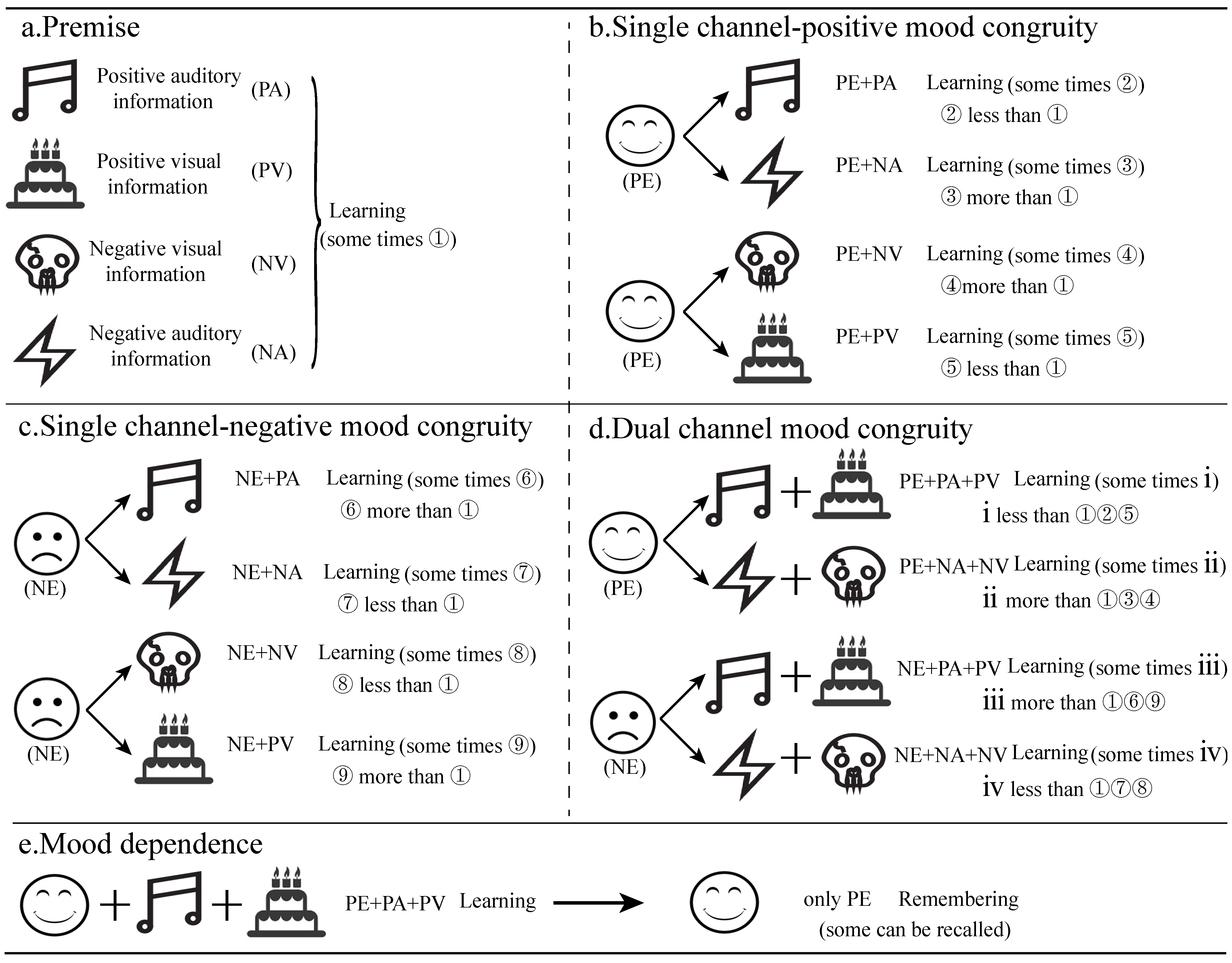
3. Multimodal Mood Consistency and Mood Dependency
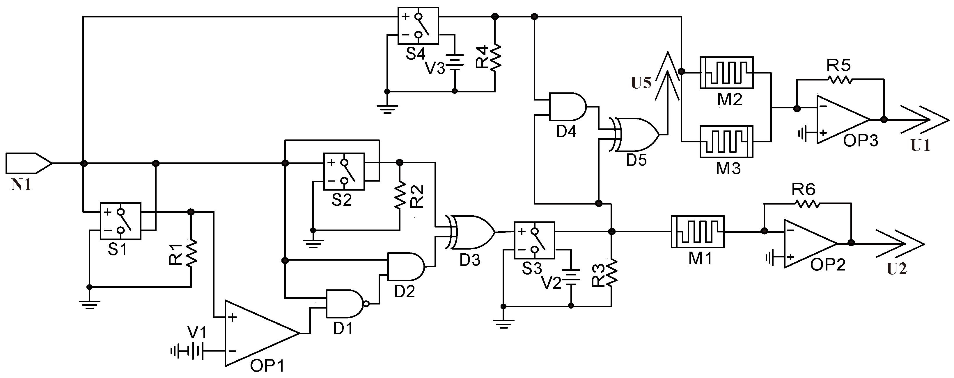
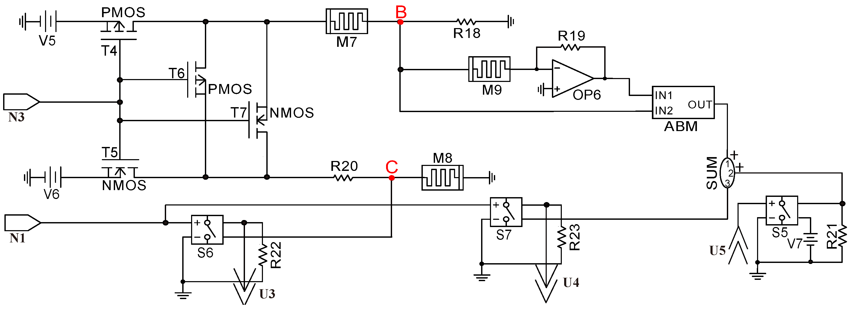
The research on neural networks for multimodal mood consistency and mood dependency in this paper is shown in Figure 2. Positive auditory and visual information is expressed by PA and PV. Negative auditory and visual information is represented by NA and NV. Positive and negative emotions are expressed by PE and NE. Process a is the stage of premise. The pleasant bell is the positive auditory information; the cake is the positive visual information; the skull is the negative visual information that frightens people; the thunder and lightning that frighten people represent the negative auditory information. The individual can learn the learning materials of different senses in a period of time. Process b is a single-channel of positive mood consistency. When the individual is in a happy state of mind, the learning efficiency of learning melodious bell materials is higher than that of the normal state of mind. The learning efficiency is lower than the normal state of mind when learning the frightening thunder and sound materials. The learning efficiency of visual materials that make people afraid is lower than that of the normal mood. The learning efficiency of visual materials that make people happy is higher than that of the normal mood. Process c is the mood consistency of single-channel negative emotions. When the individual is in a sad state of mind, the learning efficiency of the cheerful auditory materials is lower than that of the normal state of mind. The learning efficiency of negative auditory and visual materials is higher than that of the normal mood. When learning visual materials that make individuals happy, the learning efficiency is lower than that of normal emotion. Process d is the dual-channel mood consistency. When the individual is in a happy mood and learning positive auditory materials and positive visual materials, the learning efficiency will be higher than that of the single-channel and normal mood. When learning negative auditory and visual materials, the learning efficiency is lower than that of the single-channel and normal mood. When individual learns positive auditory and visual materials in a sad state of mind, the learning efficiency is lower than that in the single-channel and normal state of mind. When learning negative auditory and visual materials, the learning efficiency is higher than that of the single-channel and normal mood. Process e is the mood dependency. After learning the positive materials in a happy mood, the positive materials can be recalled in a happy mood. A happy mood recalls more content and for a longer time than the normal mood.

4. Circuit Design

4.1. Voltage Control Module

The design of the voltage control module is shown in Figure 3, which is used to judge and identify external signals. N 1 is the input signal of the learning materials with different properties. If the input signal voltage is 2.1 V, it is positive auditory information. If the input signal voltage is 2.5 V, it is positive visual information. If the voltage of the input signal is 4.8 V, it is a positive visual and auditory input at the same time. If the input signal is negative, it is a negative information input. S 1 and S 2 are voltage-controlled switches, where the conduction voltage of S 1 is 2.9 V and that of S 2 is 2.4 V. O P 1 and V 1 are formed into a comparator to ensure that the voltage output by S 1 is greater than 2.9 V. The input signal and the output value of O P 1 pass through the NAND gate D 1 and the AND gate D 2 , and only the auditory signal can be output. The role of S 2 is to be turned on during the combination of visual and auditory signals, where the XOR gate D 3 is used to prevent the conflict between the auditory signal and the audio–visual signal. The voltage control switch S 3 detects whether the auditory signal and the audio–visual signal are lower than the normal value to prevent misjudgment. The memristor M 1 , operational amplifier O P 2 , and resistor R 6 are formed into a proportional operational amplifier and output to the synaptic neuron module. The output voltage of U 2 is U 2 = V O P 1 = ( R 6 / M 1 ) × V 2 . The voltage of the voltage control switch S 4 is 2.4 V, which is used to detect the visual signals. The output voltage of S 4 enters two memristors in a reverse parallel manner. The output voltage value of U 1 is U 1 = V O P 3 = ( ( R 5 × ( M 1 + M 2 ) ) / ( M 1 × M 2 ) ) × V 3 . The auditory signal and the visual signal are output to the emotion-generation module through the AND gate D 4 and the XOR gate D 5 .

4.2. Emotion Generation Module

The circuit design of the emotion module is shown in Figure 4. Different emotions with memristors as the core are expressed. N 3 is the input signal of different emotional states, and N 1 is the input signal of materials with different properties. When the signal input by N 3 is a positive mood, T 5 will be turned on and V 6 will be output. When the signal input by N 3 is a negative mood, T 4 will be turned on and V 5 will be output. T 6 and T 7 are used for the reverse output of the direction signal. The output voltages of V B and V C are V B = R 18 × V 5 / R 18 + M 7 and V C = M 8 × V 6 / R 20 + M 8 , respectively. When the voltage value of V C exceeds the threshold voltage of S 6 , the signal of V C is output and positive emotions are generated. The signal of V B is input into memristor M 9 and the IN2 port of the mathematical device ABM. The output value of O P 6 is V O P 6 = ( R 19 / M 9 ) × V B and is input into the IN1 of the ABM. The output voltage of the ABM is V A B M = V I N 2 / V I N 1 × 6 . U 5 is input into the emotion generation module in the presence of the auditory signal and the visual signal. If U 5 is at a high level, the voltage U 4 passing through S 3 is U 4 = V 7 + V A B M . Negative emotions are generated and output to the synaptic neuron module.

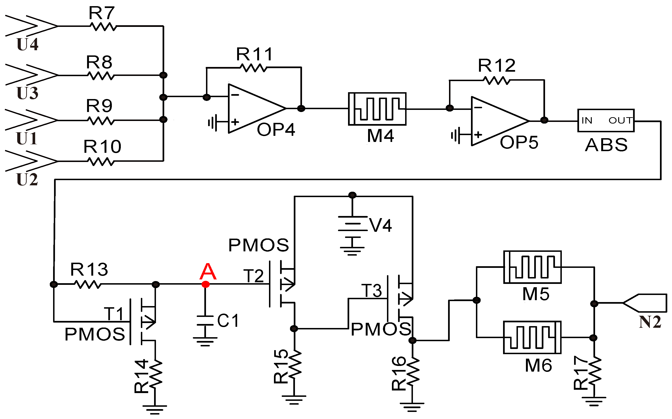
4.3. Synaptic Neuron Module

The circuit design of the synaptic neuron module is shown in Figure 5, where N 2 is the signal for individual learning. The auditory and visual signals and different emotions are connected through an adder composed of R 7 , R 8 , R 9 , R 10 , R 11 , and O P 4 . The output signal of O P 4 is transmitted to the memristor M 4 . M 4 , R 12 , and O P 5 are composed of the proportional operation, and the output voltage V O P 5 is V O P 5 = ( R 12 / M 4 ) × V O P 4 . The output value of O P 5 enters R 13 and T 1 through the absolute value module, and the capacitor C 1 will be charged. When the voltage of C 1 exceeds the threshold voltage of T 2 , T 2 is off and T 3 is on. Memristors M 5 and M 6 are connected in a reverse parallel manner, and R 17 is used to process the input voltage; finally, the learning signal is obtained. If there is no input signal from the synaptic neuron module, T 1 will be connected to discharge C 1 , and the synaptic neuron circuit will return to its initial state. If the input voltage time is too short and the voltage of C 1 does not reach the threshold voltage of 1 V, the circuit will not be activated, indicating that the synaptic neuron circuit can effectively prevent the instantaneous pulse interference of the circuit.

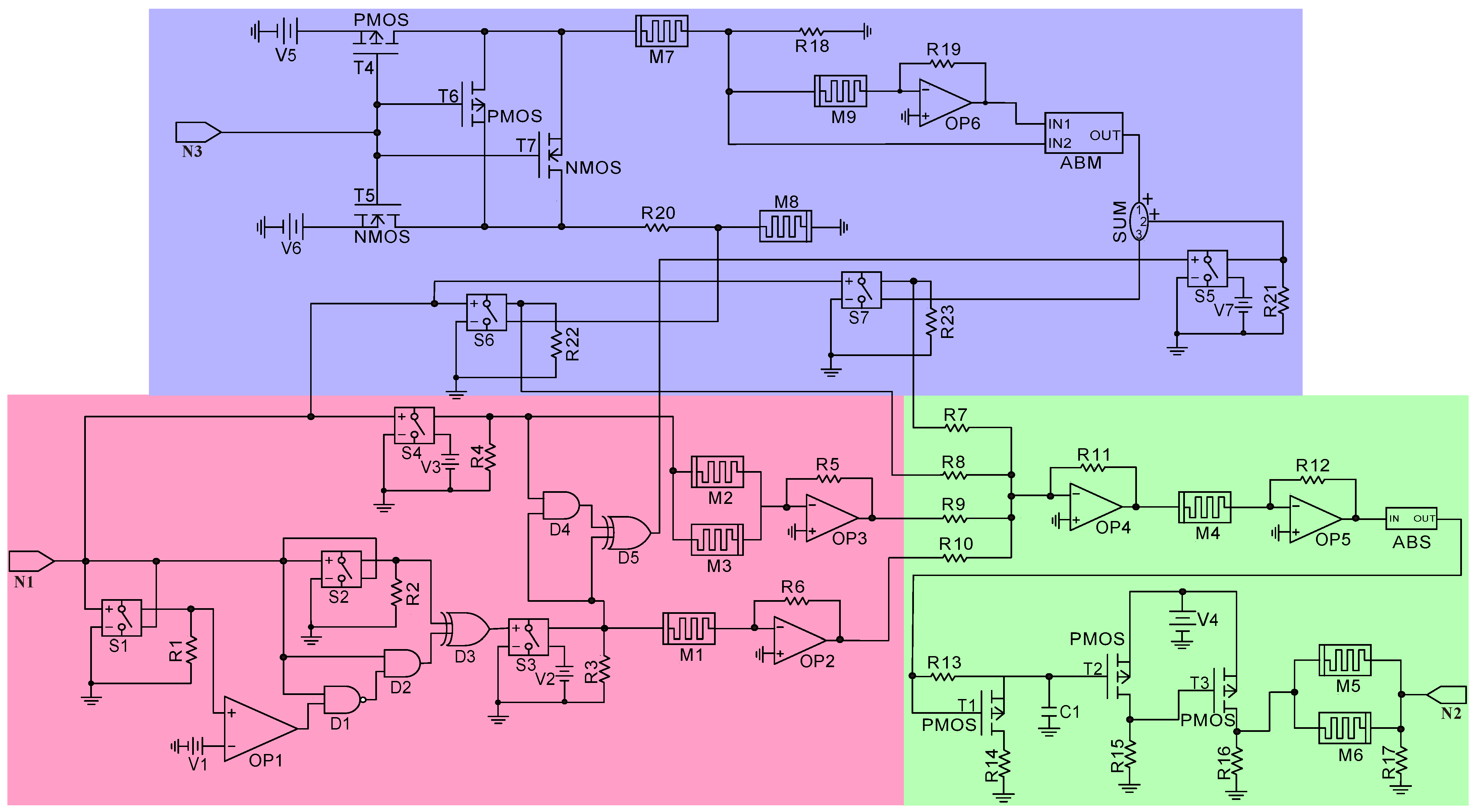
4.4. Complete Circuit

The complete circuit design is shown in Figure 6, in which the voltage control module, the emotion generation module, and the synaptic neuron module are connected to each other. The designed circuit realizes the mood consistency and mood dependency of single the-channel and dual-channel and was verified by Pspice.

5. Simulation and Analysis

5.1. Learning the Initial Situation

The simulation results with only learning materials and no emotional participation are shown in Figure 7. The red line, the blue line, and the green line represent only auditory materials, only visual materials, and audio–visual materials, respectively. The voltage of the auditory signal U 2 increases continuously when the auditory material is repeatedly learned. The memristance of memristor M 1 decreases continuously until the voltage at the U A point is greater than 1 V, and the auditory information was learned in 110 s. Similarly, the voltage of U 1 increases continuously when the visual materials are learned, and the rate of change is greater than that of the auditory signals. The memristance of memristor M 2 also decreases with the change of U 1 . The visual information was learned in 102 s when the voltage of the U A point was less than 1 V. The learning efficiency of visual and auditory dual-channel materials is obviously higher than that of single-channel materials. U A changes faster when audio–visual materials are combined, and the materials were learned in 38 s.

5.2. Single-Channel Mood Consistency

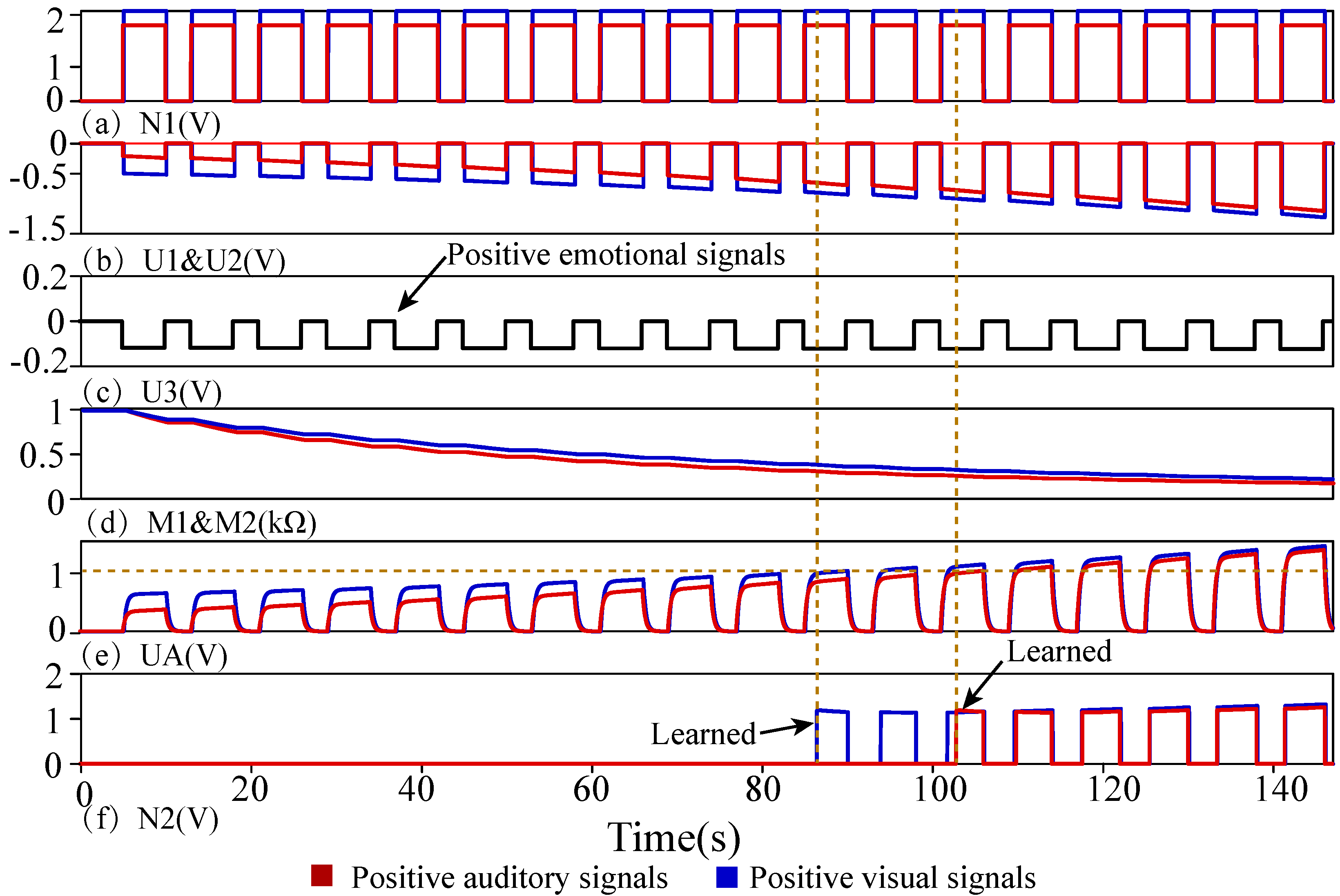
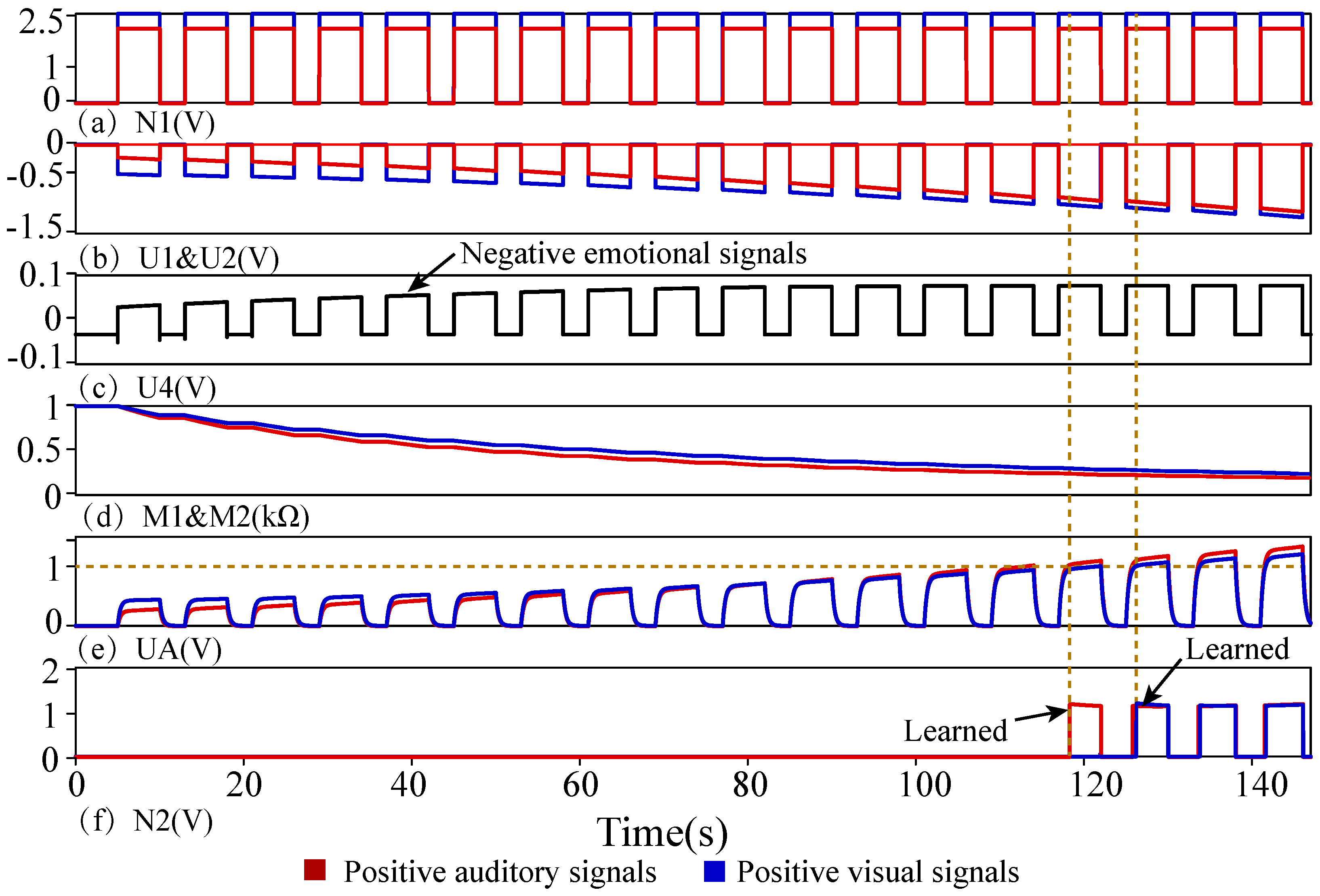
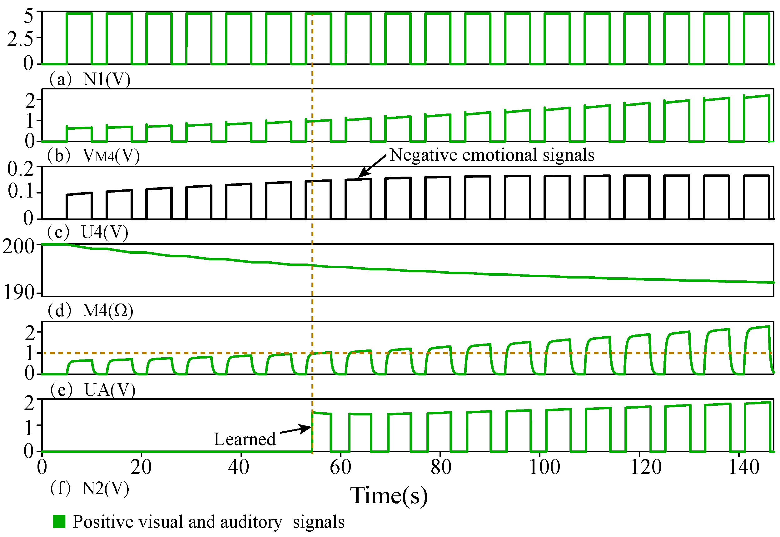
5.2.1. Different Emotional Effects of Single-Channel Positive Materials

The simulation diagram of single-channel passive visual information and passive auditory information learning in a positive emotion and a negative emotion is shown in Figure 8 and Figure 9. Under the influence of a positive emotion, the learning efficiency of positive visual and auditory information will be improved according to the consistency of the mood. In Figure 8, U 3 is the signal of the positive emotion, promoting the learning of positive information. The voltage of U A changes faster than that without emotional influence. Positive auditory materials need 103 s to be learned, and positive visual materials need 86 s to be learned, which are faster than learning without emotional influence. In Figure 9, U 4 is the signal of the negative emotion, which will inhibit the learning of positive information. The voltage of U A changes more slowly than that without emotional influence. Positive auditory materials need 125 s to be learned, and positive visual materials need 118 s to be learned, which are slower than learning without emotional influence.

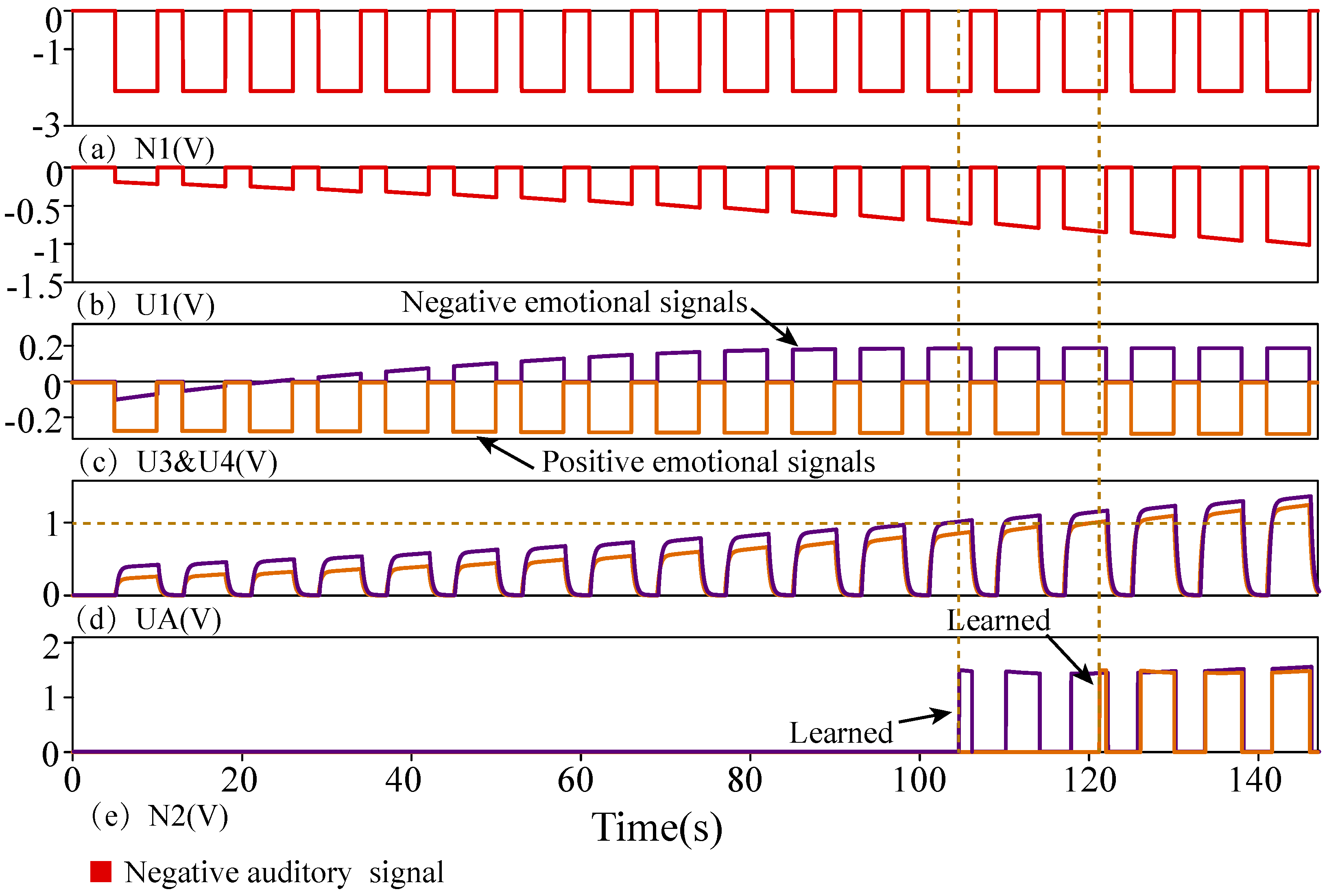
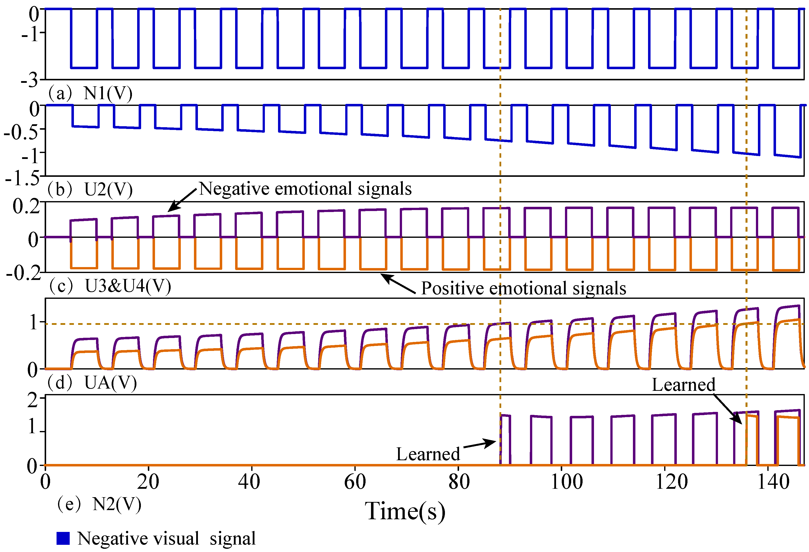
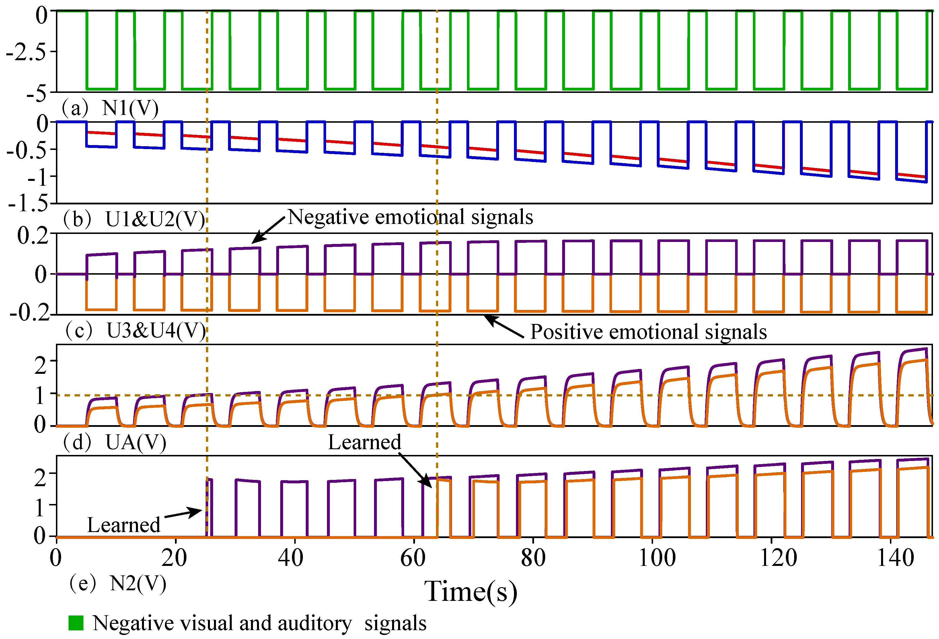
5.2.2. Different Emotional Effects of Single-Channel Negative Materials

The simulation diagram of single-channel negative auditory information and negative visual information learning under the influence of positive emotions and negative emotions is shown in Figure 10 and Figure 11. In Figure 10, U 1 is the auditory signal, U 3 is the signal of the negative emotion, and U 4 is the signal of the positive emotion. The positive emotion will reduce the learning efficiency of negative auditory information, and the voltage of U A changes more slowly than when there is no emotional impact. The positive auditory materials needed 122 s to be learned, which is slower than learning without emotional influence. The negative emotion can improve the learning efficiency of negative auditory information, and the voltage of U A changes faster than that without the influence of emotion. The negative auditory materials needed 103 s to be learned, which is faster than learning without emotional influence.
In Figure 11, U 1 is the visual signal, U 3 is the signal of the negative emotion, and U 4 is the signal of the positive emotion. Similarly, the positive emotion will reduce the learning efficiency of negative visual information, and positive visual materials needed 136 s to be learned. The negative emotion will improve the learning efficiency of negative visual information, and negative auditory materials needed 89 s to be learned.

5.3. Dual-Channel Mood Consistency

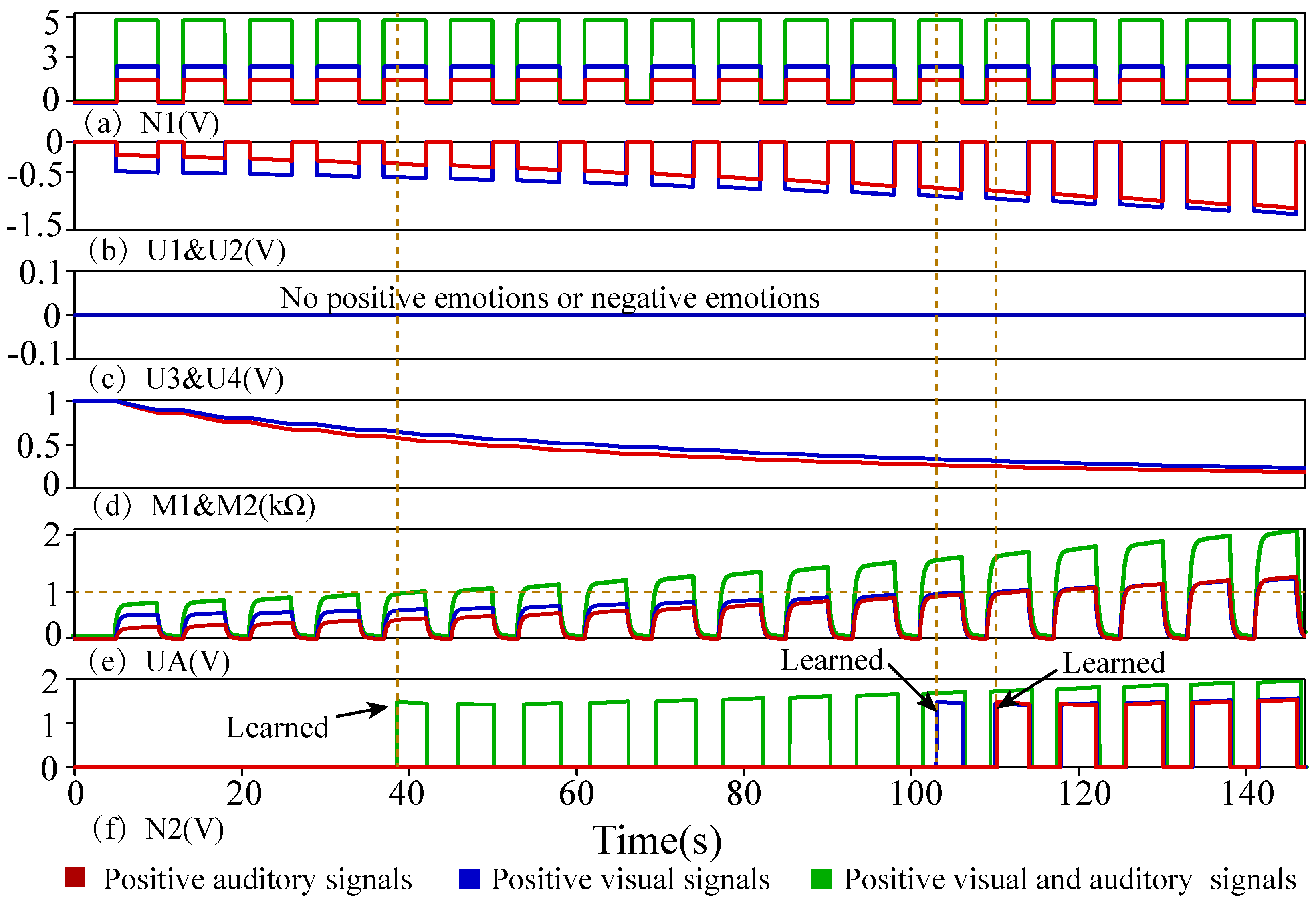
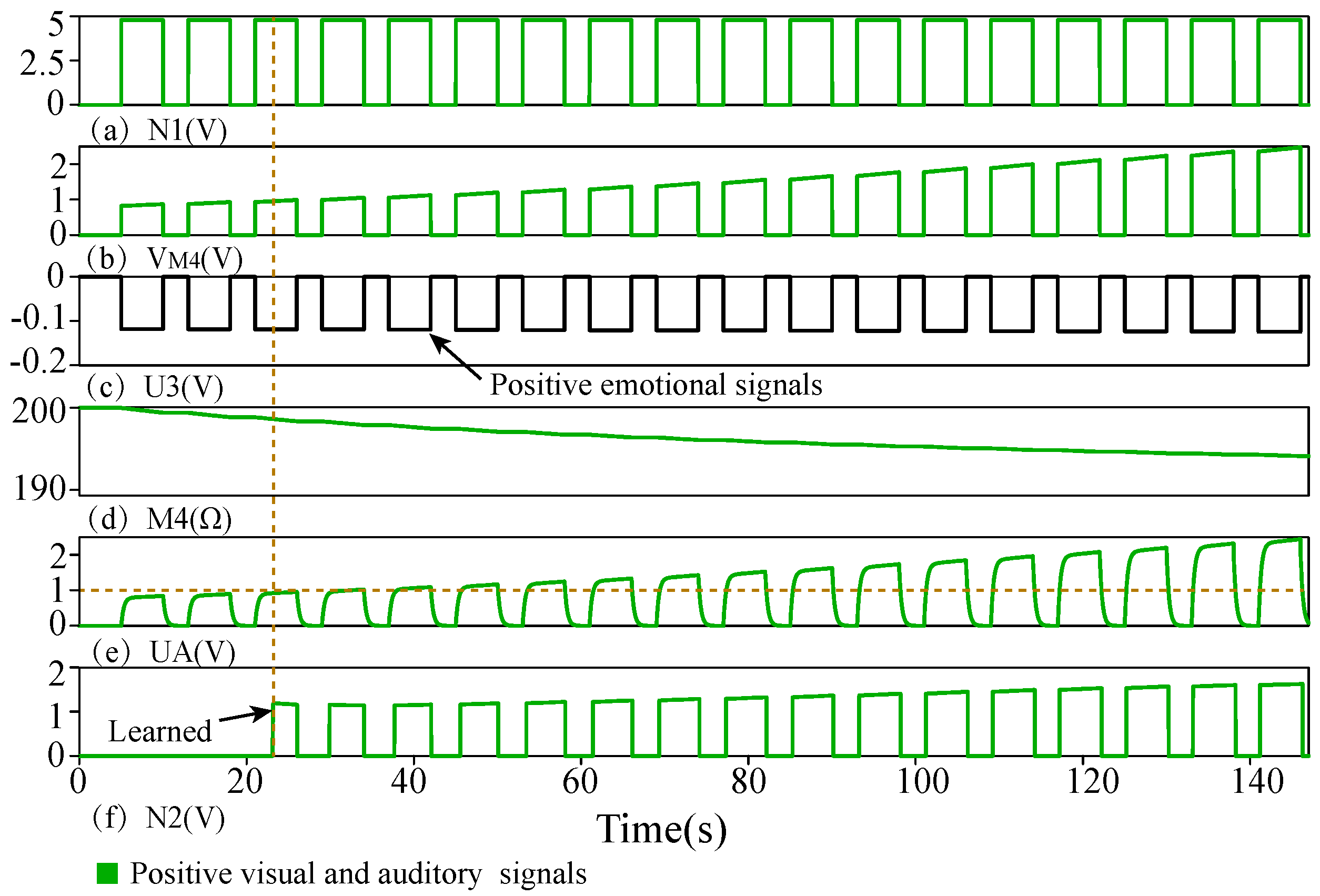
5.3.1. Different Emotional Effects of Dual-Channel Positive Materials

The simulation diagram of active material learning under the combination of visual and auditory channels is shown in Figure 12. U 3 is the signal of the positive emotion, which can promote the learning of positive materials. Under the influence of positive emotion, the voltage increase of U A is obvious. The learning time of the channel of audio–visual integration under positive emotion was far less than that of the single-channel, and the materials of audio–visual integration were learned in 28 s. The simulation results in the negative environment are shown in Figure 13. U 4 is the signal of the negative emotion, which can inhibit the learning of positive materials. Under the influence of the negative emotion, the voltage of U A rises slowly. The learning time of the channel of the audio–visual combination under the negative emotion was far less than that of the single-channel, and the materials of the audio–visual combination were learned in 54 s.

5.3.2. Different Emotional Effects of Dual-Channel Negative Materials

The simulation results of dual-channel negative materials in positive and negative emotion learning are shown in Figure 14. U 1 and U 2 are negative visual and auditory signals, respectively, and U 3 and U 4 are positive emotional signals and negative emotional signals, respectively. The negative emotion can promote the learning of dual-channel negative materials, and the voltage of U A rises rapidly. Under the mechanism of mood consistency, negative materials were learned in 66 s. The positive emotion can inhibit the learning of the negative audio–visual materials, and the voltage speed increase of U A is slower. When the mood is inconsistent, the learning time of negative materials will be longer, which was 24 s.

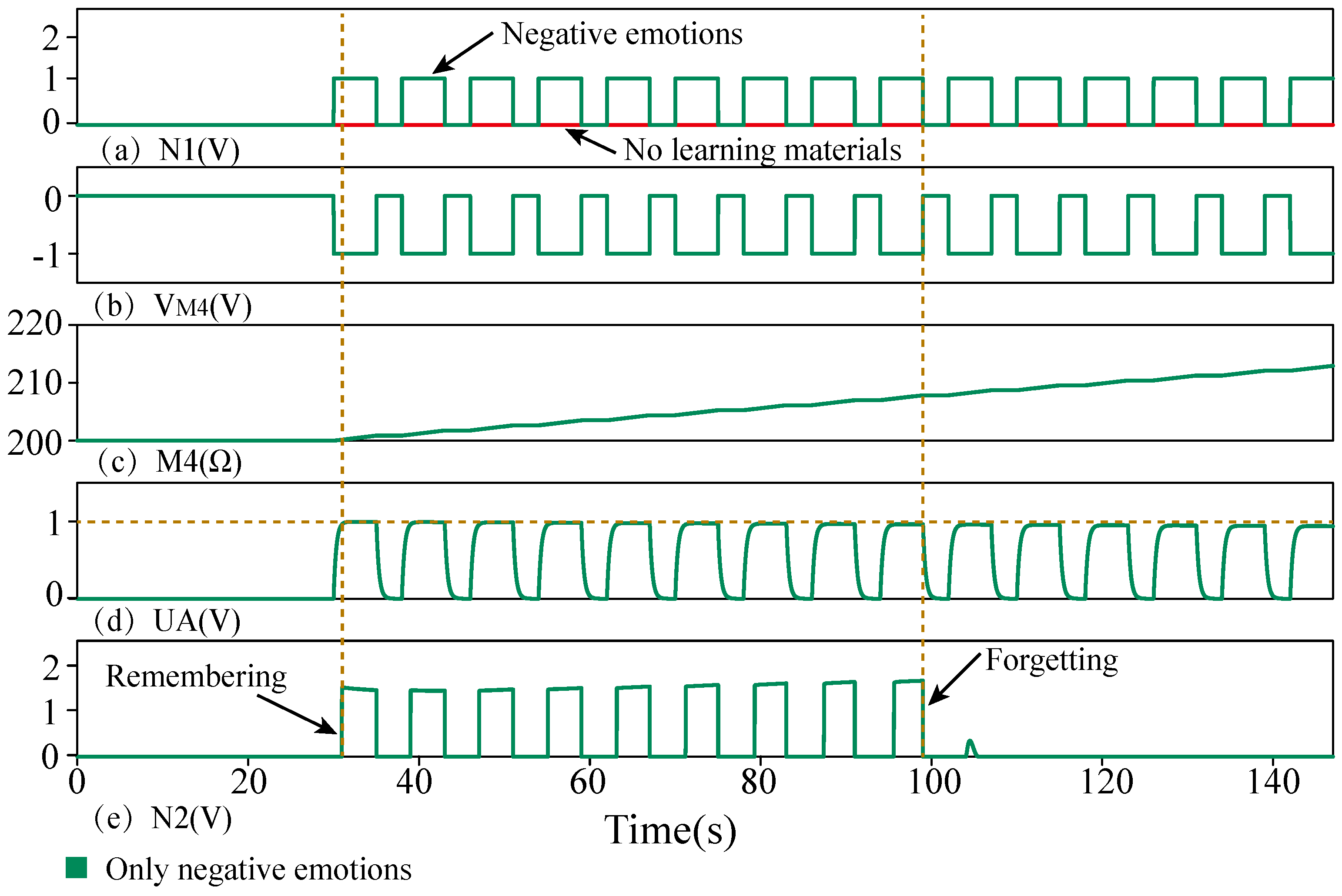
5.4. Mood Consistency and Mood Dependency

The learning cycle data in different states are shown in Table 2. The simulation results of mood dependency are shown in Figure 15. Mood consistency is the learning stage. If the normal emotions and learning materials are the same, the learning efficiency will be improved. Mood dependency is the forgetting stage. If the mental state of memory is the same as that of learning, the individual can recall more than normal. In 25 s, when there was only a negative emotion, the resistance of memristor M 4 started to rise. The learning content is recalled when there is only a negative emotion. After a period of time, when the voltage value of U A is less than the threshold voltage of T 2 , the learning content is forgotten.
As shown in Table 3, the functions realized by different works were compared. Compared with the above work [17,19,21,22,23], more functions were realized in our memristor circuit. For example, by discussing the role of the single-channel and dual-channel in mood consistency, we also considered the function of mood dependency.

6. Conclusions

In this paper, a neural network circuit based on memristors for multimode mood consistency and mood dependency was designed. Single-channel visual and auditory mood consistency were achieved, and dual-channel mood consistency was also considered. In addition, the function of mood dependency was realized through a memristor circuit. However, although mood consistency and mood dependency were realized, the influence of external factors on mood dependency was not taken into account. The influence between more channels of coordinated learning and emotion needs further exploration and research. Therefore, we need further research on mood dependency to provide a reference for further brain-like neural networks.

Author Contributions

Methodology, Y.W. (Yangyang Wang); software, Y.W. (Yanfeng Wang); validation, J.S.; formal analysis, Y.W. (Yangyang Wang) and J.S.; investigation, P.L.; resources, Y.W. (Yanfeng Wang); data curation, J.S.; writing—original draft, Y.W. (Yangyang Wang); writing—review and editing, J.S.; visualization, P.L.; funding acquisition, Y.W. (Yanfeng Wang). All authors have read and agreed to the published version of the manuscript.

Funding

This work was supported in part by the National Natural Science Foundation of China under Grants 62276239 and 62272424, in part by the Joint Funds of the National Natural Science Foundation of China under Grant U1804262, in part by Henan Province University Science and Technology Innovation Talent Support Plan under Grant 20HASTIT027, in part by Zhongyuan Thousand Talents Program under Grant 204200510003, in part by Zhongyuan Talents Program under Grant ZYYCYU202012154, in part by Henan Natural Science Foundation–Outstanding Youth Foundation under Grant 222300420095, and in part by the Henan Province Key Research and Development and promotion special project (Science and technology) under Grant 21210221044.

Institutional Review Board Statement

Not applicable.

Informed Consent Statement

Not applicable.

Data Availability Statement

Not applicable.

Conflicts of Interest

The authors declare no conflict of interest.

References

  1. Tyng, C.M.; Amin, H.U.; Saad, M.N.; Malik, A.S. The influences of emotion on learning and memory. Front. Psychol. 2017, 8, 1454. [Google Scholar] [CrossRef] [PubMed]
  2. Strukov, D.B.; Snider, G.S.; Stewart, D.R.; Williams, R.S. The missing memristor found. Nature 2008, 453, 80–83. [Google Scholar] [CrossRef] [PubMed]
  3. Ding, T.; Wang, Z.; Rong, Z. Intermittent control for quasisyn chronization of delayed discrete-time neural networks. IEEE Trans. Cybern. 2021, 51, 862–873. [Google Scholar] [CrossRef] [PubMed]
  4. Liu, X.; Zeng, Z. Memristor crossbar architectures for implementing deep neural networks. Complex Intell. Syst. 2022, 110, 91–104. [Google Scholar] [CrossRef]
  5. Sun, J.; Han, G.; Zeng, Z.; Wang, Y. Memristor-based neural network circuit of full-function Pavlov associative memory with time delay and variable learning rate. IEEE Trans. Cybern. 2020, 50, 2935–2945. [Google Scholar] [CrossRef]
  6. Liu, G.; Shen, S.; Jin, P.; Wang, G.; Liang, Y. Design of memristor-based combinational logic circuits. Circuits Syst. Signal Process. 2021, 40, 5825–5846. [Google Scholar] [CrossRef]
  7. Wen, S.; Xiao, S.; Zeng, Z.; Yan, Y.; Huang, T. Adjusting learning rate of memristor-based multilayer neural networks via fuzzy method. IEEE Trans. Comput. Aided Des. Integr. Circuits Syst. 2019, 38, 1084–1094. [Google Scholar] [CrossRef]
  8. Liu, X.; Huang, Z.; Wunsch, C. Memristor-based HTM spatial pooler with on-device learning for pattern recognition. IEEE Trans. Syst. Man Cybern. Syst. 2022, 3, 1901–1915. [Google Scholar] [CrossRef]
  9. Chen, W.; Qi, Z.; Akhtar, Z.; Siddique, K. Resistive-RAM-based in-memory computing for neural network: A review. Electronics 2022, 11, 3667. [Google Scholar] [CrossRef]
  10. Wen, S.; Han, J.; Wei, H.; Yang, Y.; Guo, Z.; Zeng, Z.; Huang, T.; Chen, Y. Memristive LSTM networks for sentiment analysis. IEEE Trans. Syst. Man Cybern. Syst. 2021, 51, 1794–1804. [Google Scholar] [CrossRef]
  11. Qiu, R.; Dong, Y.; Jiang, X.; Wang, G. Two-neuron based memristive hopfield neural network with synaptic crosstalk. Electronics 2022, 11, 3034. [Google Scholar] [CrossRef]
  12. Ranjan, R.; Ponce, P.M.; Hellweg, W.L.; Kyrmanidis, A.; Saleh, L.A.; Schroeder, D.; Krautschneider, W.H. Integrated circuit with memristor emulator array and neuron circuits for biologically inspired neuromorphic pattern recognition. J. Circuits Syst. Comp. 2017, 26, 1750183. [Google Scholar] [CrossRef] [Green Version]
  13. Lu, W.; Bao, N.; Zheng, T.; Zhang, X.; Song, Y. Memristor-based read/write circuit with stable sontinuous read operation. Electronics 2022, 11, 2018. [Google Scholar] [CrossRef]
  14. Wen, S.; Wei, H.; Yan, Z.; Guo, Z.; Yang, Y.; Huang, T.; Chen, Y. Memristor-based design of sparse compact convolutional neural networks. IEEE Trans. Netw. Sci. Eng. 2020, 7, 1431–1440. [Google Scholar] [CrossRef]
  15. Yang, L.; Wang, C. Emotion model of associative memory possessing variable learning rates with time delay. Neurocomputing 2021, 460, 117–125. [Google Scholar] [CrossRef]
  16. Hong, Q.; Yan, R.; Wang, C.; Sun, J. Memristive circuit implementation of biological nonassociative learning mechanism and its applications. IEEE Trans. Biomed. Circuits Syst. 2020, 14, 1036–1050. [Google Scholar] [CrossRef] [PubMed]
  17. Hittner, E.F.; Stephens, J.E.; Turiano, N.A.; Gerstorf, D.; Lachman, M.E.; Haase, C.M. Positive affect is associated with less memory decline: Evidence from a 9-year longitudinal study. Psychol. Sci. 2020, 31, 1386–1395. [Google Scholar] [CrossRef] [PubMed]
  18. Wang, Z.; Wang, X.; Lu, Z.; Wu, W.; Zeng, Z. The design of memristive circuit for affective multi-associative learning. IEEE Trans. Biomed. Circuits Syst. 2020, 14, 173–185. [Google Scholar] [CrossRef]
  19. Sun, J.; Han, J.; Wang, Y.; Liu, P. Memristor-based neural network circuit of emotion congruent memory with mental fatigue and emotion inhibition. IEEE Trans. Biomed. Circuits Syst. 2021, 15, 606–616. [Google Scholar] [CrossRef]
  20. Wang, Z.; Wang, X.; Zeng, Z. Memristive circuit design of brain-like emotional learning and generation. IEEE Trans. Cybern. 2021, 53, 222–235. [Google Scholar] [CrossRef]
  21. Wang, Z.; Wang, X.; Zeng, Z. Memristive circuit design of brain-inspired emotional evolution based on theories of internal regulation and external stimulation. IEEE Trans. Biomed. Circuits Syst. 2021, 15, 1380–1392. [Google Scholar] [CrossRef] [PubMed]
  22. Wang, L.; Zou, H. A new emotion model of associative memory neural network based on memristor. Neurocomputing 2020, 410, 83–92. [Google Scholar] [CrossRef]
  23. Wang, Z.; Hong, Q.; Wang, X. Memristive circuit design of emotional generation and evolution based on skin-like sensory processor. IEEE Trans. Biomed. Circuits Syst. 2019, 13, 631–644. [Google Scholar] [CrossRef] [PubMed]
  24. Pershin, Y.V.; Ventra, M.D. Experimental demonstration of associative memory with memristive neural networks. Neural Netw. 2010, 23, 881–886. [Google Scholar] [CrossRef] [PubMed] [Green Version]
  25. Xie, G.; Liu, G.; Zhang, S. Expression of emotion using a system combined artificial neural network and memristor-based crossbar array. In Proceedings of the 2016 35th Chinese Control Conference (CCC), Chengdu, China, 27–29 July 2016; pp. 9837–9841. [Google Scholar]
  26. Erk, S.; Kiefer, M.; Grothe, J.; Wunderlich, A.P.; Spitzer, M.; Walter, H. Emotional context modulates subsequent memory effect. NeuroImage 2003, 18, 439–447. [Google Scholar] [CrossRef]
  27. Lewis, P.A.; Critchley, H.D. Mood-dependent memory. Trends Cogn. Sci. 2003, 7, 431–433. [Google Scholar] [CrossRef] [PubMed]
  28. Kvatinsky, S.; Ramadan, M.; Friedman, E.G.; Kolodny, A. VTEAM: A general model for voltage-controlled memristors. IEEE Trans. Circuits Syst. II Express Briefs 2015, 62, 786–790. [Google Scholar] [CrossRef]
  29. Ren, K.; Zhang, K.; Qin, X.; Yang, F.; Sun, B.; Zhao, Y.; Zhang, Y. VETAM-M: A general model for voltage-controlled memcapacitive-coupled memristors. IEEE Trans. Circuits Syst. II Express Briefs 2015, 69, 1717–1721. [Google Scholar] [CrossRef]
  30. Zhang, Y.; Wang, X.; Li, Y.; Friedman, E.G. Memristive model for synaptic circuits. IEEE Trans. Circuits Syst. II Express Briefs 2016, 64, 767–771. [Google Scholar] [CrossRef]
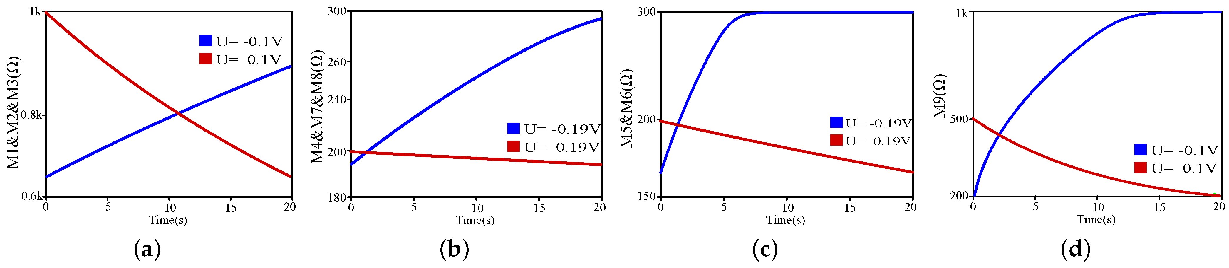
Figure 1. The curves of memristance when the memristors in Table 1 are applied with different voltages. The blue line (negative voltage) represents the increase of the memristance, and the red line (positive voltage) represents the decrease of the memristance. (a) Memristance curve of M1, M2, and M3. (b) Memristance curves of M4, M7, and M8. (c) Memristance curves of M5 and M6. (d) Memristance curves of M9.
Electronics 12 00521 g001
Figure 2. Illustration of multimodal mood consistency and mood dependency.
Electronics 12 00521 g002
Figure 3. Voltage control module. R 1 = R 2 = R 3 = R 4 = 1 k Ω , R 5 = R 6 = 100 Ω . V 1 = 2.9 V, V 2 = 2.1 V, V 3 = 2.4 V. D 1 is the NAND gate; D 2 and D 4 are the AND gate; D 3 and D 5 are the XOR gate. O P 1 , O P 2 , and O P 3 are operational amplifiers. M 1 , M 2 and M 3 are memristors.
Electronics 12 00521 g003
Figure 4. Emotion-generation module. V 18 = 50 Ω , V 19 = V 20 = V 21 = V 22 = V 23 = 1 k Ω . V 5 = 2 V, V 6 = 2 V, V 7 = 0.12 V. T 4 , T 6 , and T 7 are PMOSs and T 5 is an NMOS. M 7 , M 8 and M 9 are memristors.
Electronics 12 00521 g004
Figure 5. Synaptic neuron module. R 7 = R 8 = R 9 = R 10 = R 11 , R 17 = 100 Ω , R 12 = 200 Ω , R 13 = R 14 = 1 k Ω , R 15 = R 16 = 2 k Ω . V 4 = 3 V, C 1 = 300 μ V. O P 4 , and O P 5 are operational amplifiers. T 1 , T 2 , and T 3 are PMOSs. M 4 , M 5 and M 6 are memristors.
Electronics 12 00521 g005
Figure 6. Complete circuit.
Electronics 12 00521 g006
Figure 7. Learning the initial situation. (a) Input signal. (b) Visual signal U 1 , auditory signal U 2 . (c) Positive emotion signal U 3 , negative emotion signal U 4 . (d) Variation curve of memristors M 1 and M 2 . (e) Voltage curve of U A . (f) Output signal.
Electronics 12 00521 g007
Figure 8. Positive emotional effects of single=channel positive materials. (a) Input signal. (b) Visual signal U 1 , auditory signal U 2 . (c) Positive emotion signal U 3 , negative emotion signal U 4 . (d) Variation curve of memristors M 1 and M 2 . (e) Voltage curve of U A . (f) Output signal.
Electronics 12 00521 g008
Figure 9. Negative emotional effects of single-channel positive materials. (a) Input signal. (b) Visual signal U 1 , auditory signal U 2 . (c) Positive emotion signal. (d) Variation curve of memristors M 1 and M 2 . (e) Voltage curve of U A . (f) Output signal.
Electronics 12 00521 g009
Figure 10. Different emotional effects of single-channel negative auditory signal. (a) Input signal. (b) Visual signal. (c) Negative emotion signal. (d) Voltage curve of U A . (e) Output signal.
Electronics 12 00521 g010
Figure 11. Different emotional effects of single-channel negative visual signal. (a) Input signal. (b) Auditory signal. (c) Positive emotion signal U 3 , negative emotion signal U 4 . (d) Voltage curve of U A . (e) Output signal.
Electronics 12 00521 g011
Figure 12. Positive emotional effects of dual-channel positive visual and auditory signals. (a) Input signal. (b) Voltage of memristor M 4 . (c) Positive emotion signal. (d) Variation curve of memristor M 4 . (e) Voltage curve of U A . (f) Output signal.
Electronics 12 00521 g012
Figure 13. Negative emotional effects of dual-channel positive visual and auditory signals. (a) Input signal. (b) Voltage of memristor M 4 . (c) Negative emotion signal. (d) Variation curve of memristor M 4 . (e) Voltage curve of U A . (f) Output signal.
Electronics 12 00521 g013
Figure 14. Different emotional effects of single-channel negative visual and auditory signals. (a) Input signal. (b) Visual signal U 1 , auditory signal U 2 . (c) Positive emotion signal U 3 , negative emotion signal U 4 . (d) Voltage curve of U A . (e) Output signal.
Electronics 12 00521 g014
Figure 15. Mood dependency. (a) Input signal. (b) Voltage of memristor M 4 . (c) Variation curve of memristor M 4 . (d) Voltage curve of U A . (e) Output signal.
Electronics 12 00521 g015
Table 1. Parameters setting of memristors.
Parameters M 1 and M 2 and M 3 M 4 and M 7 and M 8 M 5 and M 6 M 9
D (nm)3333
R o n ( Ω ) 1001050100
R o f f ( Ω ) 2 k 300300 1 k
R i n i t ( Ω ) 1 k 200200500
V T + (V)0.10.190.190.1
V T (V)−0.1−0.19−0.19−0.1
μ v ( m 2   s 1   Ω 1 ) 1.6 × 10 18 1.6 × 10 17 1.6 × 10 17 1.6 × 10 17
i o n (A)1111
i o f f (A) 1 × 10 5 1 × 10 5 1 × 10 5 1 × 10 5
i 0 (A) 1 × 10 3 1 × 10 3 1 × 10 3 1 × 10 3
p10101010
Table 2. Learning cycle data in different states.
No.Normal StatePositive EmotionsNegative Emotions
1102 s86 s118 s
2110 s103 s125 s
338 s28 s54 s
4/136 s89 s
5/122 s103 s
6/66 s24 s
1–6 are, respectively, positive single-channel visual signals, positive single-channel auditory signals, positive dual-channel visual and auditory signals, negative single-channel visual signals, negative single-channel auditory signals, negative dual-channel visual and auditory signals.
Table 3. Comparison of the functions implemented by several different works.
WorkMemristor CircuitMood ConsistencyMood DependencyDual Channel
Audio–Visual Integration
[17]NoYesNoNo
[21]YesNoNoNo
[22]YesNoNoNo
[23]YesNoNoNo
[19]YesYesNoNo
this workYesYesYesYes
Disclaimer/Publisher’s Note: The statements, opinions and data contained in all publications are solely those of the individual author(s) and contributor(s) and not of MDPI and/or the editor(s). MDPI and/or the editor(s) disclaim responsibility for any injury to people or property resulting from any ideas, methods, instructions or products referred to in the content.

