1. Introduction
Recently, the interest in unmanned aerial vehicles (UAVs) has increased dramatically due to advancements in artificial intelligence and microprocessor technology, as specialized aerial vehicles or aerial robots can be developed that are capable of executing complex tasks that are difficult or dangerous to perform using other aerial craft, especially by those with human operators on board [
1]. Due to their user-friendliness, safety, cost-effectiveness, and eco-friendliness, UAVs are capable of undertaking a variety of risky, long-distance missions in both military and civilian domains. Therefore, they have become an important growing sector in the aerial vehicle market [
2,
3]. Many countries around the world have highlighted the importance of developing diversified UAV technologies in order to meet various mission requirements [
4].
UAVs typically include various components, such as a flight platform, a propulsion system, an onboard electrical system, a mission load system, a control system, and a communication system. All the components mentioned above are important, but one of the most essential parts is the propulsion system, as it serves as the UAV’s power core and has a critical role in determining whether the UAV can successfully execute its tasks [
5]. Propulsion systems generally consist of energy sources and power units, which include engines and motors [
6].
In terms of energy sources, UAV propulsion systems can be broadly divided into three categories: fuel-powered propulsion systems, hybrid fuel–electric systems, and purely electric systems. Purely electric UAVs offer a broad spectrum of energy sources, including innovative options such as lithium batteries, fuel cells, supercapacitors, and solar energy [
7]. Electric propulsion systems in UAVs commonly use high-energy-density permanent magnet motors as power output devices. Additionally, they often adopt a concept in which a high-power motor system is subdivided into several lower-power motor systems with the same total power, preserving the power density and efficiency of the entire system. This property, known as the relative scale-independent feature of motors, enables the use of multiple relatively low-power motors to drive small-diameter fans, enhancing the thrust-to-weight ratio of the propulsion system, ensuring improved UAV stability, and optimizing UAV energy management strategies [
8]. This configuration is referred to as a distributed electric propulsion system.
On the other hand, UAVs equipped with conventional fuel propulsion systems offer advantages such as high payload capacity, a long endurance range, and rapid refueling capabilities [
9]. These conventional fuel propulsion systems can be categorized into two main types: piston and turbine engines [
10]. The fuel propulsion system of a UAV typically consists of a fuel supply system, an engine, a mechanical transmission, and a propeller. The engine has a key role in serving as the energy converter and power source of the UAV [
11]. Due to propeller limitations, most piston engines are suitable for low-speed, low-altitude UAVs. In contrast, modern UAVs with high-speed, high-altitude requirements commonly use turbine engines, making them the mainstream power units for UAV propulsion systems [
12].
The development of fuel propulsion systems for UAVs has already reached a high level of maturity. In the case of purely electric propulsion systems, the main limitation recorded is the energy density limit of the batteries. Therefore, fuel–electric hybrid propulsion systems are preferred [
13], as a hybrid propulsion system combines a fuel propulsion system with an electric motor in order to generate the necessary power for aircraft flight, resulting in approximately 30% fuel consumption savings compared with traditional fuel propulsion systems [
8]. In a fuel–electric hybrid propulsion system, the fuel engine and generator work to produce thrust [
14].
Broadly speaking, hybrid systems can be categorized into parallel, series, series–parallel, and complex configurations based on whether the engine directly provides thrust or not [
15].
In a parallel hybrid propulsion system, the engine and the electric motor–generator drive the propeller’s rotation in tandem through the mechanical drive transmission [
16]. The electric motor–generator’s role is to maintain the engine operating under optimal conditions. When the engine produces excess power, it is converted into electrical energy by the generator and is stored in an energy storage device. Conversely, when the engine output is insufficient, the energy storage device releases electrical energy to drive the electric motor, compensating for the power shortfall.
The key feature of a series hybrid propulsion system is that the engine does not directly supply power to the UAV. Instead, it drives a generator to produce electrical energy. This electrical energy then powers an electric motor, which ensures the fan’s rotation to generate thrust [
16]. During flight, the electric motor can drive the fan for thrust during the takeoff and landing phases, while the gas turbine can operate the electric motor, generating electrical energy during high-altitude cruising to extend the aircraft’s range.
The series–parallel hybrid structure combines aspects of both series and parallel configurations, with the power unit consisting of both an engine and an electric motor [
15]. Mechanical energy generated by the engine partly transfers to the propeller through a gearbox, while the generator produces the other portion for electric motor operation or storage in a battery. During flight, the electric motor and the fuel propulsion system collaborate to provide power for the propeller’s rotation.
In this current investigation, a proposal is advanced to extend the flight autonomy of a multi-rotor UAV by incorporating a micro-turbogenerator system onto the UAV platform. To assess the viability of this solution, rigorous testing and analysis of the micro-turbogenerator were imperative. Consequently, a specialized testing bench was conceived and developed for this purpose. Testing benches play a pivotal role in quantifying real-time motor performance with data acquisition and operational control across all modes of operation. This involves the utilization of sensors, transducers, and specialized equipment for data acquisition, as well as control elements such as relays, pressure reducers, valves, dampers, etc., for operational control. The potential for expanding measurements with additional equipment and its integration into the data acquisition and control system, along with corresponding software, is acknowledged.
Numerous scientific papers have delved into testing benches and the methodologies used for testing, including the equipment and software used (references [
17,
18,
19,
20]). However, a comprehensive presentation of the entire process encompassing the design and manufacturing of a test bench, incorporating mechanical support structures and mounting arrangements for the micro-turboengine, as well as a constructive solution for the data acquisition system, was detailed in Rad’s work [
21].
Presently, several companies are actively engaged in the development of micromotors, catering to diverse applications such as research, UAV propulsion, and electricity generation, among others. These companies include AMT Netherlands [
22], JetCat [
23], JetCentral [
24], Frank Turbine [
25], Toyota Turbine and Systems [
26], MTT Microturbine [
27], UAV Turbines [
28], Blandon Jets [
29], Brayton Energy [
30], ICR Turbine Engine Corporation [
31], TurboTech Energy [
32], PBS Aerospace [
33], KingTech Turbines [
34], and numerous others.
The augmentation of unmanned aerial vehicle (UAV) endurance constitutes a pivotal aspect in the realm of UAV technology and its ongoing advancement. Heightened endurance capabilities empower UAVs to engage in protracted missions, cover expansive distances, and maintain flight over extended durations without necessitating recharging or supplementary power inputs. This extended endurance potential unlocks novel avenues for applications encompassing surveillance, exploration, goods delivery, and beyond.
Our research actively contributes to this imperative by conceptualizing a hybrid propulsion system designed to substantially amplify the endurance of UAVs. This innovation not only bestows UAVs with heightened versatility but also augments their overall efficiency. The reduction in reliance on traditional power sources, inherent to this hybrid propulsion system, yields notable cost and resource savings. Consequently, our research aligns with broader initiatives in the continuous development of UAV technology, actively contributing to the heightened autonomy and efficiency of these devices. Such advancements wield a considerable impact across diverse application domains.
2. Materials and Methods
2.1. Selection of Propulsion Systems and the Design of the Test Bench and Its Components
The undertaken investigation aimed to evaluate the feasibility of extending the flight autonomy of a multi-rotor UAV platform, specifically, a quadcopter, with the integration of a micro-turbogenerator system.
Schematic representations of two distinct propulsion systems were devised for comparative analysis. The first diagram illustrates a UAV outfitted with an electric propulsion system (depicted in
Figure 1a), while the second diagram portrays a UAV equipped with a micro-turbogenerator, exemplifying a hybrid propulsion system (depicted in
Figure 1b).
Prior to the integration of the micro-turbogenerator onto a UAV, a comprehensive testing phase was imperative to elucidate its functional parameters and delineate the requisite control laws for UAV management. To facilitate this, a purpose-designed test bench was conceived and developed, equipped with all necessary apparatus for the control and monitoring of operating parameters pertaining to the hybrid propulsion system.
This test bench played a crucial role in ascertaining the performance metrics of the micro-turbogenerator system and in formulating a control law essential for maintaining equilibrium between the power generated by the system and the power consumed by the UAV. The primary objective of the assembly was to scrutinize the configuration, wherein the micro-turbogenerator is directly linked to the generator responsible for producing electric current for the UAV’s motors. Two distinct testing methodologies were selected, focusing on electric consumption and the AC-DC transformer:
Option A: The electric consumer consists of electric resistors grouped in parallel and a rectifier bridge.
Option B: The electric consumer consists of an EDF (Electric Ducted Fan)-type electric motor with a rectifier bridge.
Option A incorporates a testing bench featuring an array of electric resistors organized in parallel to effectively consume the electric power generated by the micro-turbogenerator. Control over these resistors is facilitated with a relay system that systematically opens and closes the circuit. Furthermore, the energy transformation system converting AC to DC, emanating from the generator, is illustrated with the depiction of a rectifier bridge.
In contrast, Option B uses an electric motor equipped with a ducted fan as the primary consumer, with the capacity to fully utilize the electric power generated by the micro-turbogenerator. This configuration emulates the authentic on-board infrastructure of a UAV, providing a simulation that closely mirrors real-world conditions. Similar to Option A, the electric transformer is represented by a rectifier bridge.
The design of the testing bench was executed utilizing SolidEdge 2021 CAD software, resulting in a detailed 3D CAD model, as depicted in
Figure 2.
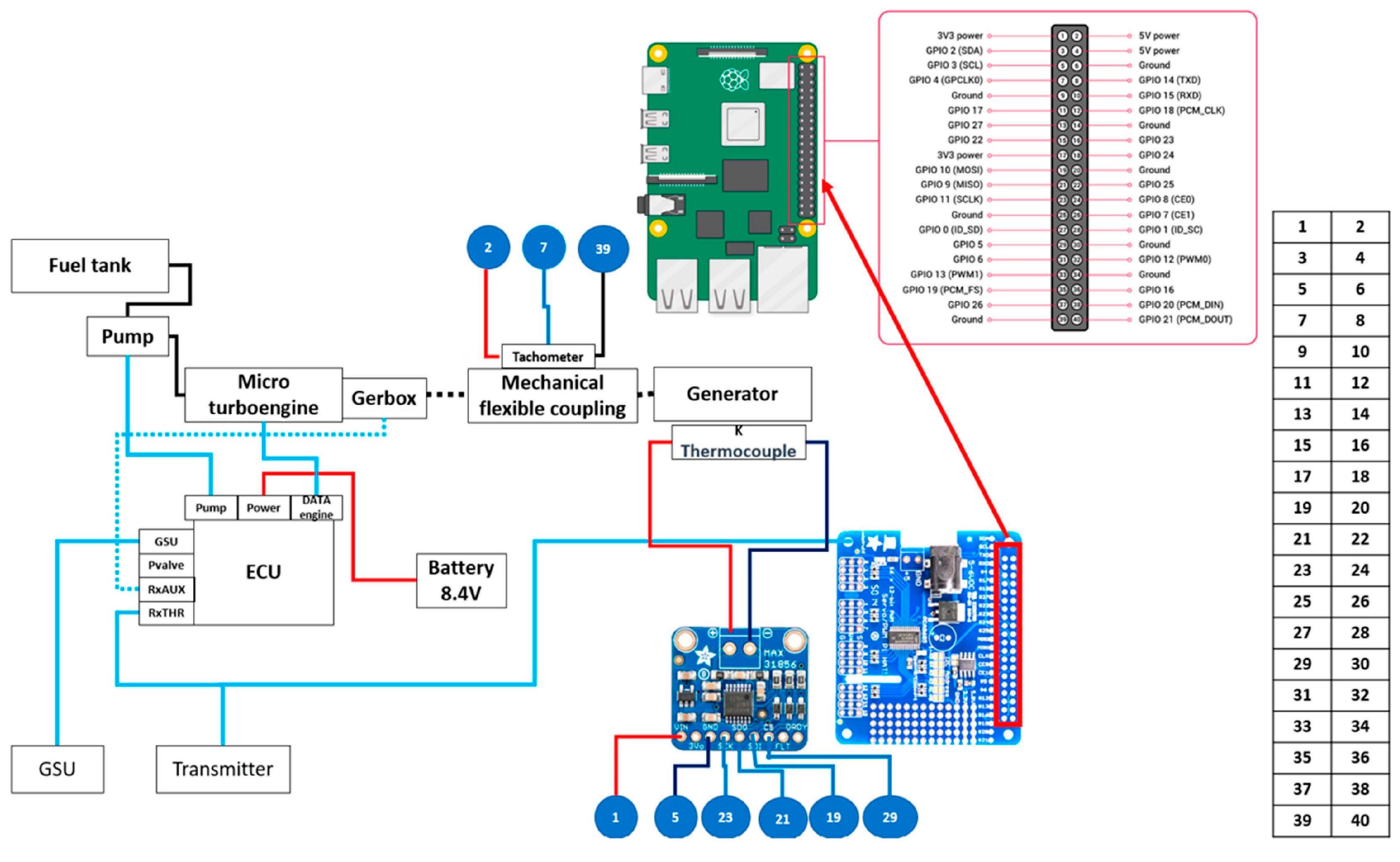
The fabrication of the test bench exclusively used commercially available materials, components, and equipment. The foundational structure of the test bench comprises a metallic frame, functioning as a metallic skeleton, crafted from extruded aluminum profiles with the dimensions of 40 × 20 mm and 20 × 20 mm. The chosen profile type features a V-slot channel, enabling the insertion of specially designed nuts for the assembly of additional components on the test bench. The metallic frame is terminated at the bottom part with four wheels, facilitating the mobility of the bench. The main components of the testing setup include a KingTech K45TPG4 turboprop, a flexible coupling, a U13 II KV65/KV130 generator, a fuel tank, electric resistors, an EDF consumer, an ESC (Electronic Speed Controller) for the EDF, a rectifier bridge, a Raspberry Pi 4 computer, a relay system, and sensors.
The micromotor selected for this application yields a power output of 5.2 kW, achieved at a combustion gas temperature of 700 °C. The micromotor’s maximum turbine speed is recorded at 170,000 RPM. To regulate the speed at the shaft to 10,000 RPM, a reducer with a reduction ratio of 1:17 is seamlessly integrated into the testing bench.
This micromotor exhibits versatility in fuel options, accommodating diesel, Jet A1, and kerosene. Additionally, oil is introduced into the fuel mixture to facilitate lubrication for the bearings and gears within the reducer. The micromotor is coupled to the generator responsible for generating electric current for the UAV’s consumers, which, in this scenario, encompasses the electric motors and other components slated for UAV integration.
An integral component of the setup is an SBC (single-board computer) with multifaceted functionalities, serving crucial roles in the overall system architecture. The functions of the SBC are the following:
Start/stop the micromotor.
Control the micromotor speed.
Calculate the fuel level in the tank.
Measure the generator speed.
Control the EDF motor.
Control the relay system for connecting/disconnecting the electric resistors.
The regulation of both the micromotor and the EDF motor is facilitated with PWM (Pulse Width Modulation) signals, which are generated by the PWM signal amplifier hat mounted on the Raspberry Pi 4 board. Additionally, the computer controls a relay module responsible for the opening and closing of relay circuits. Input data acquisition is conducted by the computer, specifically reading the generator speed with a dedicated module.
The fully configured test bench, embodying all these components and functionalities, is visually presented in the images depicted in
Figure 3.
2.2. Control System of the Test Bench
Two diagrams for the testing methods (Option A and B) were developed and are presented in
Figure 4. Both diagrams include the EDF motor consumer and the electric resistor system consumer. In Option B, the SBC controls the EDF motor with a PWM signal provided to the motor’s ESC, while in Option A, the SBC controls a relay system that opens/closes the circuit for each resistor connected in parallel.
Each electric resistor has a value of 10 Ohms, and at an applied voltage of 48 V, it results in an electric current of 4.8 A. The maximum power that the electric resistor can dissipate is 300 W, and the electric power applied at 48 V is 230.4 W. With 16 resistors in parallel, it results in a maximum power dissipation of 3686.4 W. The chosen electric resistor is HS300 10R F.
Figure 5 shows an electrical diagram of the control and command system within the testing bench.
The KingTech Turbines K45TPG4 micromotor is supplied with kerosene fuel from the fuel tank via an electric pump. The operation of this electric pump is controlled and powered by the ECU (Engine Control Unit), which serves as the micromotor’s control computer. The ECU, in turn, receives power from a LiPo battery operating at 8.4 V. Manual control of the ECU is facilitated by a GSU (Ground Support Unit), which is a touchscreen control display. The ECU governs and energizes the micromotor, collecting data and supplying electrical energy to the micromotor’s starter. It regulates the micromotor’s speed by modulating the fuel flow directed to the micromotor. As such, the ECU executes start/stop commands and speed control, receiving PWM signals from both the transmitter and the SBC (Raspberry Pi) computer.
The transmitter, characterized as ELRS, captures commands transmitted by a remote controller manually operated by a human operator. The PWM signal originating from the SBC is automated and managed with a Python programming language script. The SBC, embodied by a Raspberry Pi 4, is equipped with a PWM HAT (Hardware Attached on Top) for enhanced control over PWM signals. Within the SBC setup, two additional devices are integrated: a MAX 31856 thermocouple reader connected to a type K thermocouple, measuring the temperature in degrees Celsius on the generator’s stator, and a HALL sensor for measuring the generator’s speed. The HALL sensor interacts with a magnet mounted on the elastic coupling, generating a signal upon each rotation, subsequently utilized for calculating the rotational speed using Equation (1).
where:
RPM—Rotational speed of the generator [rpm].
Count—The number of magnet passes in front of the HALL sensor.
f—Frequency [Hz].
The electrical diagram for the electric resistor system is presented in
Figure 6.
In the system configuration, a relay system interfaces with the SBC. The AC electrical power generated by the micromotor flows through the rectifier bridge, facilitating the conversion of AC current to DC. Subsequently, this DC power is distributed to 16 electric resistors connected in parallel. Each electric resistor’s connection is routed through a relay under the control of the SBC. The electrical diagram, as illustrated in
Figure 7, elucidates the wiring configuration, showcasing the relay-controlled power distribution to each electric resistor. With the integration of this electrical schematic and corresponding programming, precise control over power consumption is achieved by selectively activating or deactivating individual electric resistors.
Figure 7 also depicts the electrical connection for electric consumer Option B, where the electric consumer is the EDF motor. The AC-DC conversion is accomplished with the rectifier bridge in this scenario. It is worth noting that this option may necessitate voltage stabilization for optimal operation.
The control system of the testing bench is necessary for controlling, regulating, and optimizing the micro-turbogenerator.
Figure 8 presents the flowchart diagram of the testing bench.
The SBC, embodied by the Raspberry Pi 4, operates as the computing platform running a Python script. The input signals processed by the SBC consist of the temperature, measured in degrees Celsius, from the generator’s stator, and the generator’s speed, obtained with the mounted tachometer. In response, the SBC issues two commands: one to the ECU, governing the micromotor’s speed, and the other to the ESC, managing the speed of the EDF motor.
The control law dictating the micro-turbogenerator’s operation relies on readings from the generator’s speed. The script undergoes calibration based on testing results and is designed to function autonomously upon integration into the UAV platform. The primary objective of the script is to ensure the start/stop functionality and operation of the micro-turbogenerator on the UAV platform. Consequently, the micromotor’s speed must be dynamically adjusted in harmony with the energy consumption of the UAV under development.
The equilibrium in power supply is crucial, where the generator’s power output must match the power consumed by the UAV. The micromotor supplies the generator’s power, considering mechanical losses and the generator’s efficiency (approximately 86%). The control law factors into the generator’s speed to regulate the micromotor’s speed. A decrease in the generator’s speed indicates an increase in power consumed by the UAV, necessitating an elevation of the micromotor’s speed and, consequently, the mechanical power at the shaft. Conversely, an increase in the generator’s speed implies a reduction in power consumed by the UAV, prompting a decrease in the micromotor’s speed. The control law incorporates considerations for the efficiency of the generator and the micromotor’s free turbine, both dependent on speed. This necessitates varying the speed according to a law established by testing on the testing stand.
2.3. Testing Method and Procedures
The micro-turbogenerator was tested in both configurations (Options A and B), using the electric resistors and the EDF. The system was operated using a controller with two throttlers, a throttler for the fuel flow of the micromotor and a throttler for power. A two-stage testing campaign was performed: first, the micromotor was powered and then it idled without a consumer. After stabilizing the micromotor, the EDF consumer/electric resistors’ system was connected to 50% of the throttle for power, and then the voltage U increased by 2 V until the value of 25 V was reached. This increase in electrical voltage was achieved by modifying the fuel throttler. When the value of 25 V was reached, it was kept constant, and the electrical intensity was varied. This was achieved by varying the throttle for the electric consumer as well as for the fuel flow. The controller in the starting position with the two throttles is shown in
Figure 9a, while
Figure 9b shows the controller with the fuel throttler idling and the power throttler in the 50% consumer stage.
3. Results
The results registered during the testing of the propulsion system are presented in
Table 1.
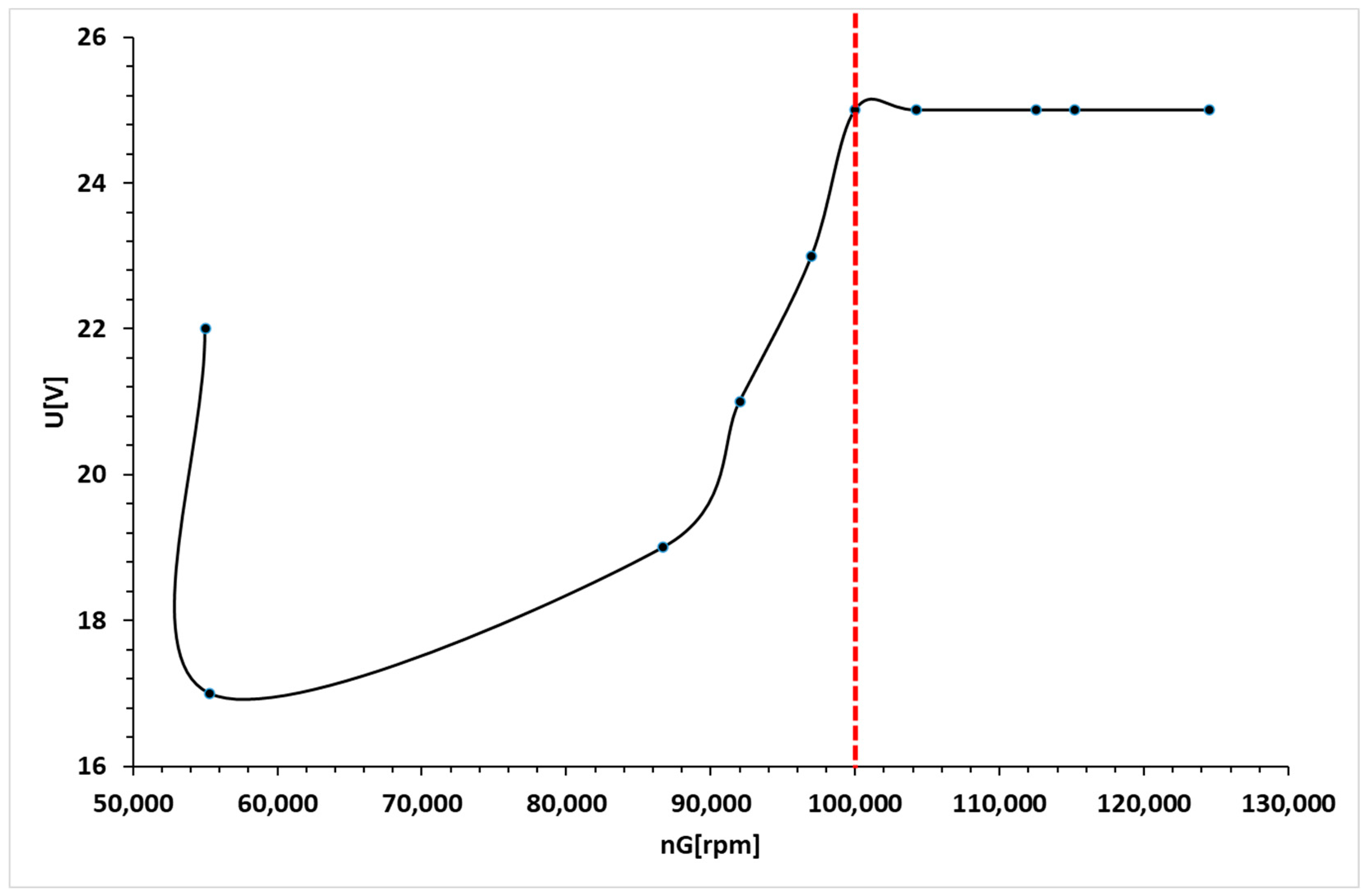
The initial data point on the graph depicted in
Figure 11 corresponds to the micro-turbogenerator operating in the absence of any consumer. Upon connecting the EDF consumer/electric resistor system, the speed of the reducer gearbox experiences a decrease initially. Subsequently, it resumes an upward trajectory as the power consumption escalates due to an increase in voltage, achieved by adjusting the fuel throttler. This trend persists until reaching the delineated red line, attributable to an elevation in amperage resulting from variations in both the fuel and power throttlers.
It is noteworthy that the speed of the nG micro-turbogenerator group exhibits a distinct variation compared with the reducer gearbox speed. This discrepancy arises due to the unique nature of their linkage: the micro-turbogenerator group is not mechanically connected to the reducer but is instead gas-dynamically linked. The return observed in the micro-turbogenerator group speed is a consequence of this gas-dynamic linkage rather than a mechanical coupling with the reducer.
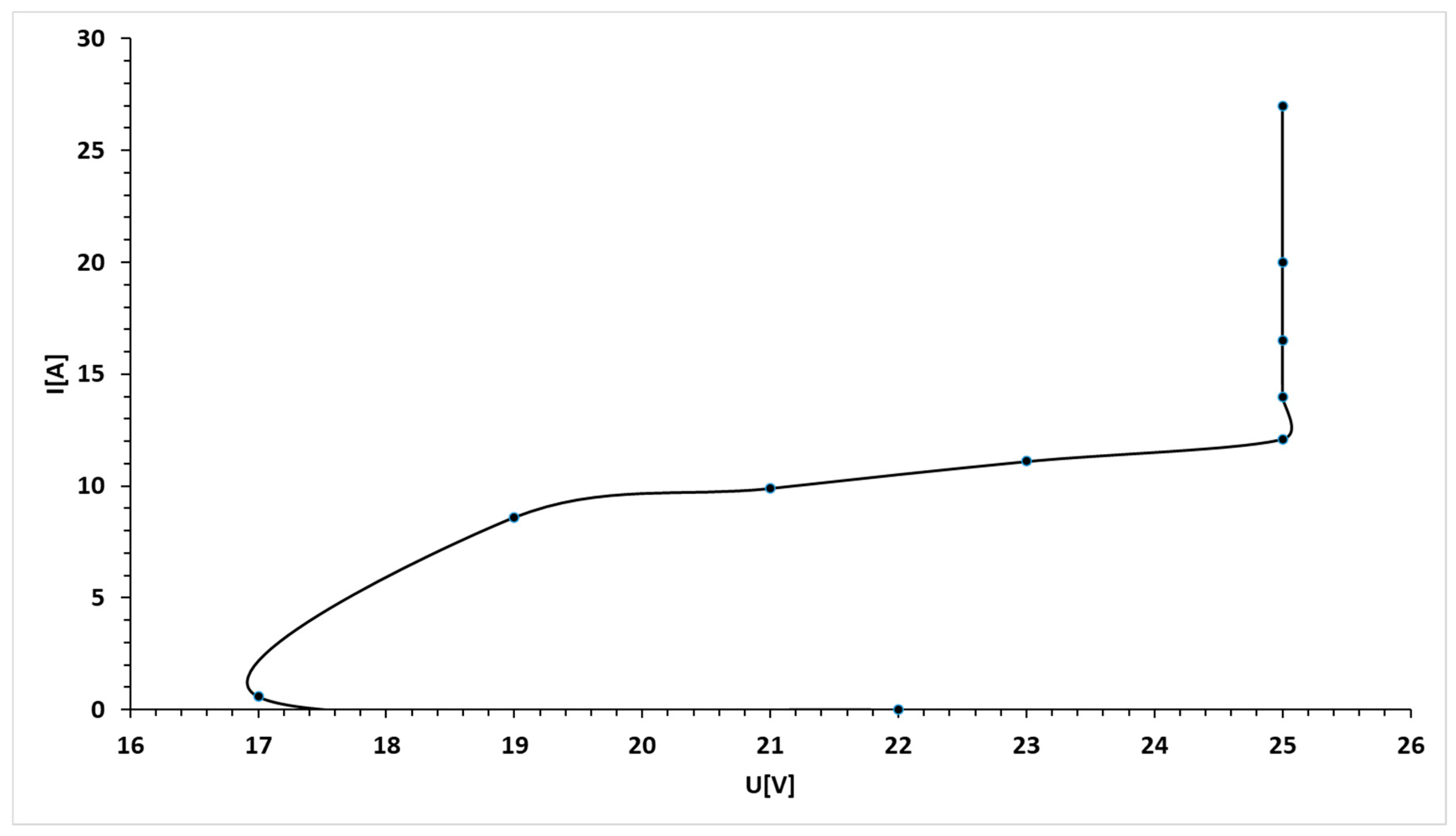
The initial data point on the graph presented in
Figure 13 corresponds to the operation of the micro-turbogenerator without any electric consumers. Upon connecting the electric consumers (either EDF or electric resistors), there was a gradual decrease in voltage until it reached a value of 17 V. Simultaneously, controlled increments in voltage, progressing by 2 V increments, were implemented, ultimately reaching a value of 25 V. These voltage adjustments were executed in tandem with an increase in speed, achieved by manipulating the position of the fuel throttle.
Upon attaining the 25 V threshold, the power was further augmented by increasing the amperage. This augmentation in power was accomplished by varying both the fuel throttle and power throttler, as evidenced by the data presented in
Figure 12 and
Figure 13. Notably, these variations were achievable by maintaining a constant voltage while concurrently elevating the speed of both the micro-turbogenerator group and the reducer.
Observing
Figure 14, a notable trend is the concurrent decrease in the speed nGB, coupled with the increase in the micro-turbogenerator’s speed. This correlation arises from the coupling of the consumer. Subsequently, the power consumption experiences an increment corresponding to changes in the fuel throttler position, progressing until reaching the marked red line in the graph. Furthermore, an additional increase in the nG speed is recorded due to an augmentation in amperage, achieved by manipulating both throttlers.
Figure 15 provides insights into the variation in amperage corresponding to changes in voltage. The coupling of power consumers is evident at the second data point on the graph, followed by a continuous rise in amperage and a simultaneous increase in voltage. This interplay reflects the dynamic relationship between amperage and voltage during the operation of the micro-turbogenerator system with connected power consumers.
4. Conclusions
A study was conducted to explore the integration of a micro-turbogenerator system into a multi-rotor UAV platform as a means of extending its flight autonomy. In order to assess the viability of this solution, a dedicated test bench was conceived and constructed. The primary objective of the test bench was to facilitate the examination and comprehension of the functional parameters and control laws governing the hybrid propulsion system before its integration into the UAV platform.
Two distinct testing methods were used, each addressing electric consumption and the AC-DC transformer:
The first method involved electric resistors arranged in parallel, along with a rectifier bridge.
The second method utilized an Electric Ducted Fan (EDF)-type electric motor with a rectifier bridge.
Throughout the testing campaign, variations in key physical parameters relevant to the command and control of the hybrid propulsion system were recorded and analyzed. The tests yielded a total power of 700 W, representing the maximum achievable while maintaining a power level of 25 V. This voltage threshold was not exceeded, as surpassing it could result in significant losses.
Future studies will focus on replacing certain components of the hybrid propulsion system, such as exploring more efficient alternatives for the generator. In future research, the generator will be replaced with an optimized one designed to deliver higher power at lower speeds. Simultaneously, the bridge rectifier will be substituted with a Power Management Unit (PMU) capable of automatically stabilizing the DC output voltage at a predetermined level, considering a specific range of AC input current. This PMU will also possess the capability to absorb energy pulses from a small LiPo battery to enhance power balance within the UAV system equipped with the micro-turbogenerator. This integration is crucial for ensuring that during rapid UAV control commands, any required energy surplus instantaneously originates from the LiPo battery without altering the power generated by the micro-turbogenerator.
Moreover, the utilization of the PMU facilitates an intricate power management strategy, permitting the seamless extraction of energy impulses from the LiPo battery for optimizing power distribution within the UAV system. The swift response of the PMU to instantaneous energy demands during rapid UAV control maneuvers ensures a dynamic equilibrium of power by tapping into the supplementary energy stored in the LiPo battery, thereby circumventing any delay in adjusting the power output of the micro-turbogenerator. This innovative approach enhances the overall efficiency and responsiveness of the UAV system, ensuring an optimal balance between power generation and instantaneous energy requirements during critical operational scenarios.
Additionally, the mechanical structure of the UAV will be designed and manufactured, and the final configuration of the propulsion system will be assembled to assess the overall capabilities of the UAV.
Also, the event-triggered security output feedback control for networked interconnected systems is subject to cyber-attacks for security. The weighted memory H∞ stabilization of time-varying delayed Takagi–Sugeno fuzzy systems for saving communication bandwidth will be considered in future work.

 ,
, 


