1. Introduction
Networked autonomous systems, such as power systems and mobile sensor networks, have become invaluable tools in various industrial and civil applications [
1]. With the widespread application of renewable energy, distributed generation (DG) integration has become an essential component of power systems. However, the extensive integration of distributed generation into the grid poses significant challenges to the stability of the power system [
2]. When integrated into the grid, frequent dynamic changes can result in voltage and frequency fluctuations, posing a threat to grid stability [
3]. Voltage-Source-Converter-based High Voltage Direct Current (VSC-HVDC) transmission, also known as flexible DC transmission in China [
4], is the key solution to address the abovementioned issues.
The modular multilevel converter is a commonly used type among VSCs. The MMC can generate high-quality voltage waveforms, reducing the need for harmonic filters. Its modular design enables fault-tolerant operation, improving system reliability [
5,
6]. Currently, in flexible DC transmission systems, the control strategy for MMC converters is mainly based on vector control. Vector control involves establishing a mathematical model in the dq coordinate system and implementing decoupled control of the MMC output current on the dq axis, thereby achieving independent control of active and reactive power output. The vector control primarily adopts a fixed-value control of DC voltage and power. While the system can effectively track the set power, it fails to achieve coordinated operation between the MMC and the AC side. When there are changes in the AC-side system, the MMC cannot respond to variations in AC system frequency and voltage. Therefore, vector control lacks the ability for autonomous frequency and voltage regulation. Moreover, MMCs based on vector control exhibit low inertia and low damping characteristics, which may pose risks such as disconnection from the grid, especially in weak electrical grid conditions [
7].
The Virtual Synchronous Generator (VSG) technology is a clever solution to address the abovementioned issues [
8]. By simulating the operation of a synchronous generator within the MMC, the VSG technology controls the output voltage and frequency of the MMC, providing inertia to the system and achieving synchronization with the grid, thereby improving grid stability and reliability. Furthermore, VSG technology enables frequency and voltage regulation in the MMC through active and reactive voltage control.
The MMC is a crucial component of flexible DC transmission, and its control methods are a research hotspot in this field. Reference [
9] presents a control scheme for DC transmission systems similar to VSG technology. This scheme provides inertia and damping responses to both asynchronously interconnected AC systems, suppressing frequency variations and power oscillations. As the energy for an inertia response comes from the DC line capacitance, it does not affect the asynchronously interconnected AC systems. This scheme also exhibits good robustness to communication delays. References [
10,
11] propose an adaptive virtual inertia control method based on droop curve adjustment. This method calculates the droop coefficient or intercept of the droop curve in real time based on the dynamic changes in voltage and the voltage rate of change, providing inertia support to the system through fast oscillations or a translation of the droop curve.
In reference [
12], a fuzzy scheduling algorithm is utilized to take into account multiple variables and constraints in microgrid systems, facilitating the flexible scheduling and optimization of the system. Fuzzy scheduling enables decision making in uncertain environments, allowing the system to adapt to changes and provide viable control strategies rapidly. However, the effectiveness of fuzzy scheduling and robust controllers greatly depends on the selection and adjustment of parameters. Extensive experimentation and optimization are necessary to determine the optimal parameter configurations, which can be time-consuming and computationally demanding. References [
13,
14] establish a functional relationship between bus voltage, the voltage rate of change, and virtual inertia based on the virtual capacitor and virtual DC motor, proposing an adaptive virtual inertia control strategy. Reference [
15] improves system stability and control accuracy by introducing new control strategies and algorithms in addition to the existing virtual synchronous generator control strategy. However, this method requires complex system modeling and control, increasing the algorithmic complexity. In reference [
16], an analysis method for the transient stability of VSGs widely applied in islanded AC microgrids is discussed. The proposed method combines the characteristics of traditional synchronous generators and inverter control, integrating VSGs with microgrid inverters to achieve coordinated stability and power control. However, the stability analysis in this method is based on established dynamic models, which may increase the complexity of model development and computational requirements for large-scale and complex microgrid systems, necessitating further optimization and validation. Reference [
17] presents a novel control strategy for frequency stability in islanded microgrids using fractional-order virtual synchronous generators. Compared to traditional virtual synchronous generators, this method incorporates fractional-order differentiation and integration operations to enhance the dynamic response of the generators, offering improved flexibility and accuracy. However, further research and experimental validation are required to determine the feasibility and performance of this method in practical applications. Careful consideration of parameter selection and adjustment is necessary for different microgrid systems and operating conditions to achieve optimal frequency stability control. Reference [
18] proposes a control concept that synthesizes an external (virtual) inertia under transient conditions to enhance grid stability. By introducing virtual inertia, additional stability support can be provided during system disturbances, aiding in the suppression of frequency deviations and voltage fluctuations. However, for the large-scale DG microgrid systems or complex grid structures, the design and optimization of virtual inertia control methods may become more challenging. Reference [
19] investigates the effectiveness of using VSG controllers through multiple test cases, which helps validate the feasibility and performance of this method under different scenarios. However, the specific working principles and implementation details of this new controller are not explicitly described in the literature, limiting our understanding of its technical complexity and feasibility. Reference [
20] proposes a control method that utilizes dynamic models of off-grid microgrids, considering multiple key factors such as load variations and the coordinated operation of multiple power sources within the microgrid. This approach allows for a more comprehensive assessment of the angular stability of the system. However, this method places high demands on computational resources, requiring real-time computations and extensive optimization, which may pose challenges in terms of hardware requirements for the controller.
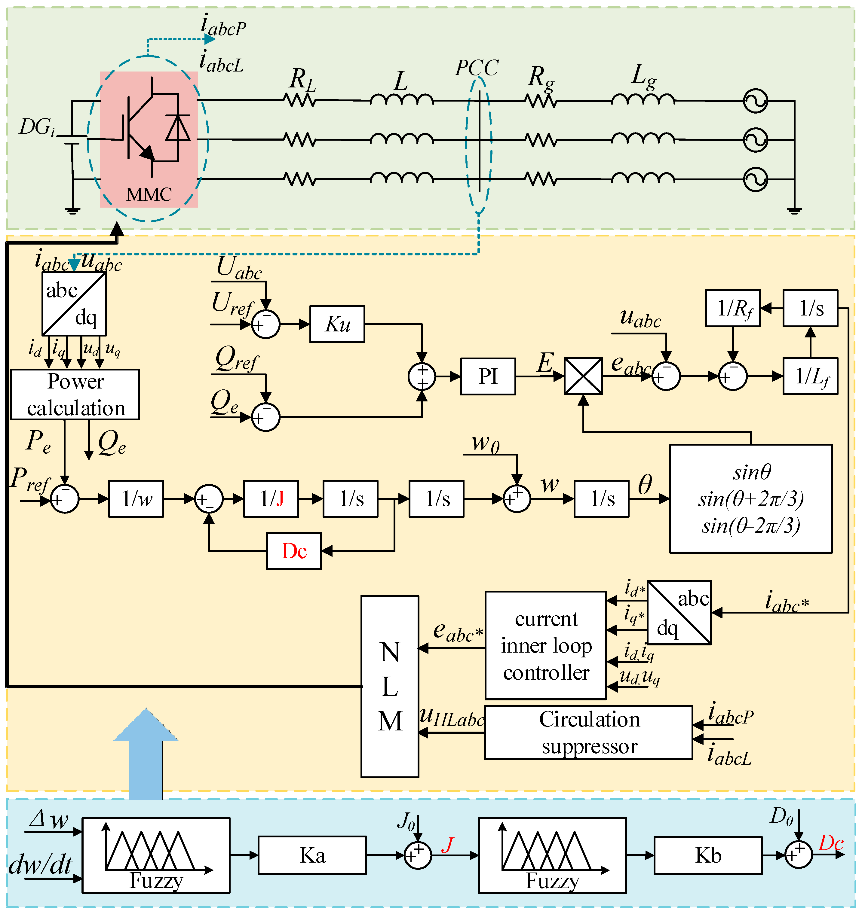
In response to the abovementioned issues, this paper proposes a VSG control method based on a fuzzy logic algorithm to regulate the MMC. The system’s virtual inertia and damping coefficient are controlled through the fuzzy logic control (FLC) algorithm, enabling adaptive adjustment. This control method addresses the insufficient inertia during the grid-connected operation of the MMC by dynamically adjusting the system’s inertia and damping. Finally, a 23-level single-end MMC-HVDC system is constructed using Matlab R2016a/Simulink simulation software to validate the effectiveness of the proposed control strategy, followed by an analysis and explanation.
The rest of the paper is structured as follows: The analysis of the MMC-VSG control structure is given in
Section 2. The controller design for the MMC-VSG control strategy based on a fuzzy logic algorithm is presented in
Section 3. Simulations are provided in
Section 4, and concluding remarks appear in
Section 5.
2. Analysis of MMC-VSG Control Structure
2.1. Mathematical Model of the MMC Converter
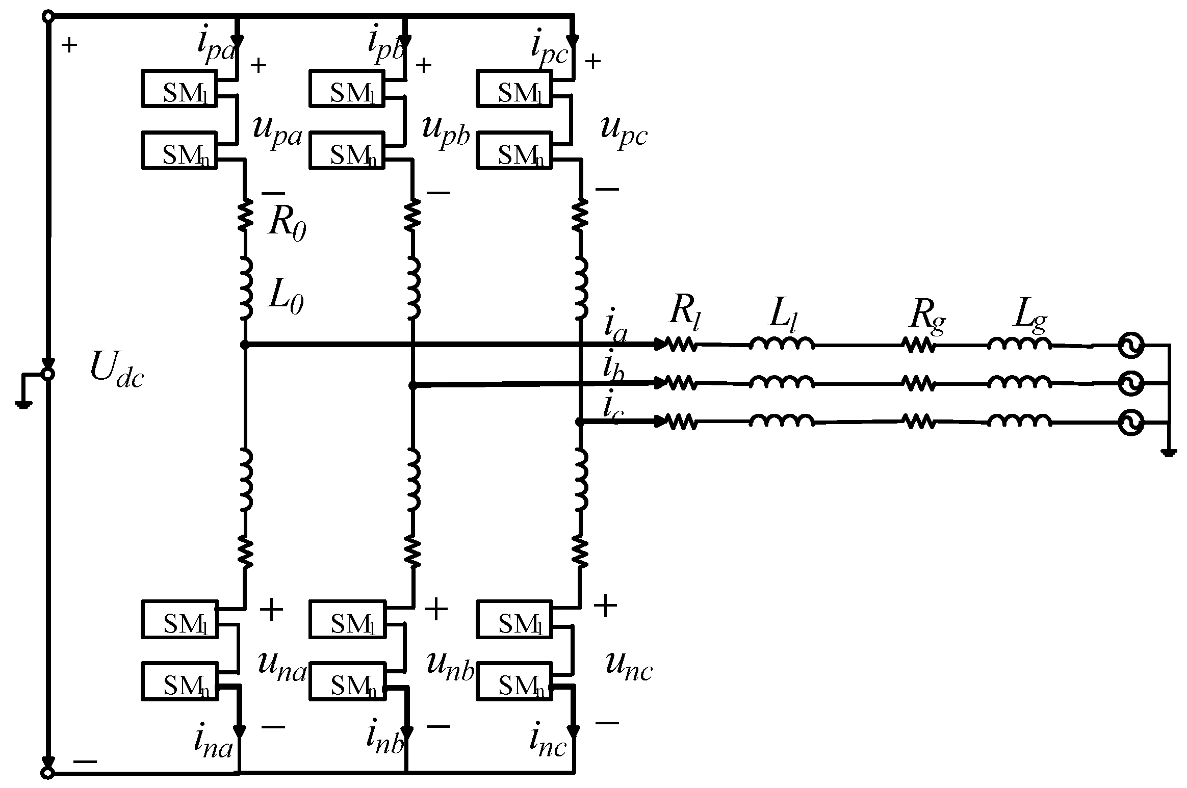
The circuit topology of the MMC during grid-connected operation is illustrated in
Figure 1. It consists of half-bridge submodules denoted as SM
1 to SM
n.
Udc represents the voltage at the DC side of the MMC. The variables
ipj and
inj (
j = a, b, c) represent the currents in the upper and lower bridge arms, respectively. The variables
upj and
unj (
j = a, b, c) represent the voltages across the upper and lower bridge arms, respectively. The variable
ij (
j = a, b, c) represents the phase currents outputted from the MMC valves.
R0 represents the resistance of the bridge arm, while
L0 represents the inductance of the bridge arm.
Rg denotes the equivalent resistance of the AC grid, and
Lg represents the equivalent inductance of the AC grid.
According to Kirchhoff’s voltage and current laws, writing down the KVL (Kirchhoff’s Voltage Law) and KCL (Kirchhoff’s Current Law) equations for the upper and lower arms of the bridge, we can obtain the following:
By combining (1) with (2) and then simultaneously solving them with (3), we obtain the following:
In the equation, the symbol
ej* is defined as the differential-mode voltage, and its expression is as follows:
2.2. Application of Virtual Synchronous Generator in MMC Converter
For the analysis, assuming a perfectly smooth rotor surface and neglecting magnetic saturation phenomena and eddy current losses in the motor, the simplified expression for the terminal voltage of the synchronous motor’s three-phase stator winding is obtained as follows [
21]:
In the equation, usj (j = a, b, c) represents the phase voltage, Rs represents the resistance of the stator winding, isj (j = a, b, c) represents the stator current, Mf represents the maximum value of the mutual inductance coefficient, and if represents the excitation current.
The rotor motion equation of the synchronous generator is expressed as follows (10) [
22]:
In the equation, Dt represents the damping coefficient, Jt represents the moment of inertia, Tm represents the mechanical torque, Te represents the electromagnetic torque, Pe represents the electromagnetic power, Pm represents the mechanical power, ω represents the angular frequency, ω0 represents the rated angular frequency, and θ represents the electrical angle.
By comparing (4) with (8), the following corresponding relationships can be obtained:
Based on the comparative analysis between the MMC system and synchronous machine system in reference [
23], it is evident that the VSG can be applied in MMC grid-connected systems. By leveraging this technology, the stability and reliability of MMC grid-connected systems can be enhanced. The VSG technology primarily achieves the control effect of a synchronous generator by simulating and simplifying the electromagnetic and mechanical equations of a synchronous generator, as represented by Equations (8) and (10). The equivalent equations are shown as follows [
19]:
In the equation,
Lf represents the virtual inductance,
Rf represents the virtual resistance,
ij* represents the output current of the VSG,
ej represents the modulation signal of the voltage in the VSG,
uj represents the output voltage of the MMC,
J represents the virtual inertia of the VSG, and
D represents the virtual damping coefficient of the VSG. Due to the presence of
J, the MMC exhibits inertia during dynamic processes. The effect of
D allows the converter to possess the capability of damping power oscillations in the grid [
24].
When the MMC converter is connected to a low-voltage power system, any changes in the load of the low-voltage power system can lead to issues such as frequency deviation or instability in the entire control system. Therefore, it is necessary to introduce active-power–frequency control. In this paper, a speed controller based on a synchronous motor is adopted, as shown below [
25]:
By substituting (14) into (13) and redefining the damping coefficient of the VSG, we obtain the following:
Furthermore, to enable the VSG technology to better adapt to the MMC, it is necessary to refer to the excitation system of a synchronous generator for reactive power–voltage control. The expression is as follows [
25]:
In the equation, Ku represents the droop coefficient, Qe represents the measured reactive power at the point of common coupling (PCC), and Uabc represents the RMS value of the AC voltage.
2.3. Impact of Virtual Inertia and Damping Coefficient on VSG
The calculation method for the active and reactive power output of the MMC is given by (17) [
24].
In (17),
Z0 and
θ can be expressed as follows:
By combining (13), (17), and (18), the natural oscillation angular frequency,
ωn, and damping ratio,
ξ, of the second-order model can be obtained [
26]:
In the equation, Kω represents the deviation coefficient.
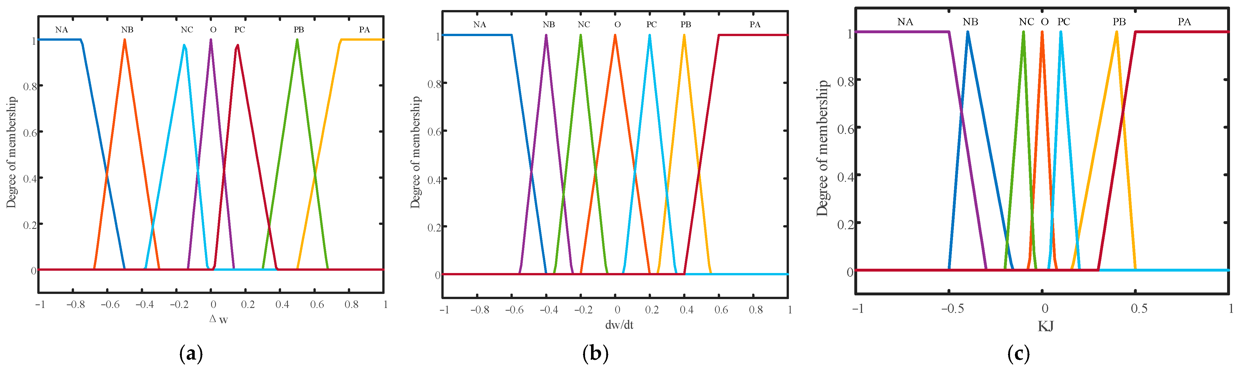
From the structural analysis above, it can be concluded that the improved VSG retains the traditional VSG design for simulating and controlling rotor motion. The virtual inertia, J, and damping coefficient, D, are important parameters that influence the characteristics of the VSG. The virtual inertia reflects the response speed of the VSG to load changes. A larger virtual inertia implies a slower response speed of the VSG to load changes, while a smaller virtual inertia indicates a faster response speed to load variations. The damping coefficient reflects the damping characteristics of the VSG. A higher damping coefficient means stronger damping properties, enabling the VSG to quickly eliminate oscillations and maintain system stability. However, an excessively large damping coefficient can also reduce the response speed of the VSG, affecting its ability to respond to load changes. Therefore, in practical applications, appropriate values for virtual inertia and damping coefficient should be chosen based on actual conditions to achieve the stable operation of the VSG and ensure its ability to respond rapidly to load variations.
When 0 <
ξ < 1 and the error is ±2%, the overshoot,
σ, and settling time,
ts, of the second-order system can be determined as follows [
26]:
From (19) and (20), it can be observed that when the virtual inertia, J, remains constant, increasing the damping coefficient, D, leads to an increase in damping ratio, ξ, resulting in a decrease in overshoot, σ, and a reduction in the settling time, ts. Conversely, when the damping coefficient, D, remains constant, increasing the virtual inertia, J, decreases the damping ratio, ξ, resulting in an increase in overshoot, σ, and an increase in the settling time, ts. Hence, the overshoot of the active power output in the transient process of the improved VSG is determined jointly by J and D.
From (14), we can derive:
From (21) and (23), it can be observed that when M is constant, increasing the damping coefficient, D, leads to a smaller Δω. Additionally, from (22) and (24), it can be seen that as N increases and J becomes larger, dω/dt decreases. Therefore, adjusting the virtual inertia, J, and damping coefficient, D, can enhance the frequency stability of the system.
4. Simulation Analysis
To validate the effectiveness of the proposed control strategy, this study constructed a 23-level single-ended MMC-HVDC system in Matlab/Simulink. The system was equipped with the aforementioned control strategy. The DC side was connected to a distributed power source with a voltage output of 11 kV, while the AC side operated at 6.6 kV. A variable-step solver, specifically ode23t, was selected for the simulation. The sampling time was set to 5 × 10
−5 s. The modulation method employed was the lowest-level approximation, focusing primarily on the simulation and analysis of the MMC inverter station. The key simulation parameters are summarized in
Table 3.
The simulation time is set to 3 s, and the traditional dual-loop control strategy is used as the control group. Under the initial state, the receiving end load is 2 MW. During stable operation, at 1.5 s, the receiving end load suddenly increases by 1 MW active power. The simulation results are as follows.
From
Figure 10 and
Figure 11, it can be observed that when the receiving end load suddenly increases at 1.5 s, under the traditional dual-loop control method, the output phase voltage and current both experience a step change at 1.5 s. This can cause a significant impact on the grid, and the voltage and current waveforms will exhibit distortion after stable operation. However, under the MMC-VSG adaptive control strategy based on the fuzzy algorithm, the output phase voltage and current do not experience a step change due to the inertia effect, and the output waveforms exhibit good quality, providing better protection for the grid. Through a fast Fourier transform (FFT) analysis, the total harmonic distortion (THD) values of the output phase voltage and current are 1.61% and 1.24%, respectively, meeting the requirements for grid connection. The specific analysis results are shown in
Figure 12 and
Figure 13.
By comparing
Figure 14 and
Figure 15, it can be observed that when the active power load at the receiving end abruptly increases to 3 MW at 1.5 s, the traditional dual-loop control strategy shows a sudden increase in the output active power from 2 MW, stabilizing at 3 MW by 1.583 s. The reactive power output also experiences a sudden increase and then restores to 0 MVar by 1.64 s, accompanied by the generation of significant harmonics.
In contrast, under the adaptive control strategy based on the fuzzy algorithm for MMC-VSG, when the load experiences a sudden increase, the system’s output active power does not undergo a sudden surge due to the inertia effect. Instead, it stabilizes at 3 MW by 1.56 s. The reactive power output, influenced by the inertia, increases from 0 MVar to 0.25 MVar and then returns to 0 MVar by 1.62 s. Comparing the two methods, the control approach proposed in this paper demonstrates a faster power response and maintains stability within a shorter period.
Under the MMC-VSG adaptive control strategy based on the fuzzy algorithm, the simulation results of the capacitor voltages and arm currents of the MMC inverter are shown in
Figure 16 and
Figure 17. It can be seen from the figures that the sorting effect of the capacitor voltages of each bridge arm is good, and the circulating current suppression effect is satisfactory. Through the FFT analysis, at t = 2 s, the THD value of the arm currents is only 2.17%, as shown in
Figure 18.
Additionally, the simulation waveforms of the virtual inertia and damping coefficient are shown in
Figure 19 and
Figure 20. From the simulation waveforms, it can be observed that the simulation results are consistent with the theoretical analysis. When the active power load at the receiving end suddenly increases, the virtual inertia, J, increases, and at the same time, the damping coefficient, D, decreases appropriately. Both of them can adaptively adjust based on the actual operating conditions of the system.
Based on the above analysis, it can be concluded that when the receiving end load undergoes a sudden increase, under the proposed control strategy in this paper, the virtual inertia and damping coefficient work in synergy to prevent the output voltage and current from experiencing a step increase. This effectively enhances the stability of the grid operation and reduces the damages caused by insufficient inertia to the grid.
5. Conclusions
This paper proposes a fuzzy-logic-based MMC-VSG control strategy suitable for weak grids. The method effectively addresses the issue of insufficient inertia when integrating distributed power sources into the grid through MMCs. Using fuzzy algorithms, the virtual inertia and damping coefficient are obtained, allowing the control system to adaptively adjust based on the operating conditions. Through the simulation analysis, when the MMC converter operates in grid-connected mode and the system load changes, this control method can effectively suppress the output voltage and power fluctuations compared to traditional dual-loop control methods. It achieves an adaptive adjustment of the virtual inertia and damping coefficient, thus verifying the effectiveness of the proposed control strategy.
In the subsequent research, the authors plan to develop an adaptive control strategy for the MMC (modular multilevel converter) grid-connected system that does not rely on intelligent algorithms. By comparing and analyzing the simulation results of this paper with the simulation results obtained using the proposed control strategy, the authors will assess the limitations and advantages of both control strategies. The objective is to identify a more suitable adaptive control strategy for the MMC grid-connected system. Additionally, the authors will integrate real-world data and scenarios to simulate and validate the proposed strategy. When feasible, the authors will also conduct experimental verification to enhance the feasibility and practical significance of this research.


