Article

Digital Restoration and 3D Virtual Space Display of Hakka Cardigan Based on Optimization of Numerical Algorithm

School of Art & Design, Guangdong University of Technology, Guangzhou 510090, China
*
Authors to whom correspondence should be addressed.
Electronics 2023, 12(20), 4190; https://doi.org/10.3390/electronics12204190
Submission received: 5 September 2023 / Revised: 29 September 2023 / Accepted: 3 October 2023 / Published: 10 October 2023
(This article belongs to the Special Issue Recent Advances in Computer Vision: Technologies and Applications)

Abstract

:
The Hakka cardigan stands as a quintessential representation of traditional Hakka attire, embodying not only the rich cultural heritage of a nation but also serving as a global cultural treasure. In this academic paper, we focus on a representative model to showcase the development of an autonomous 3D scanning system founded on an offline point cloud generation algorithm. Through a meticulous process involving the emulation of clothing pattern restoration, we employ a diverse array of software tools including Photoshop, Autodesk Maya, and CORELDRAW, harnessing graphic and image processing techniques to seamlessly transition from two-dimensional pattern restoration to a three-dimensional realm. This study revolves around the establishment of an autonomous 3D scanning system centered on a representative model, leveraging an offline point cloud generation algorithm. We incorporate the La-place mesh deformation algorithm to execute conformal transformations on neighboring vertices of motion vertices, while delving into the fundamental methodologies behind digital restoration and the three-dimensional virtual presentation of Hakka cardigans. Our experiments culminate in the measurement of six three-dimensional clothing pieces, revealing absolute deviation between the model and the actual clothing. Furthermore, when we compare the automatic measurements from 200 3D scanned human bodies with their manually obtained counterparts, the displayed measurement error hovers at approximately 0.5 cm. This research endeavor charts an expedited pathway to achieve digital restoration and three-dimensional virtual representation of Hakka cardigans. It not only offers a novel perspective for the digital revitalization of traditional clothing but also serves as a valuable augmentation to contemporary methods of preserving traditional clothing.

1. Introduction

In the realm of traditional clothing design and production, the norm has long been the use of hand-drawn or two-dimensional design sketches to envision and create three-dimensional attire meant for human wear. Unfortunately, this traditional approach comes with a host of drawbacks. The entire process, from design conception to production, is undeniably time-consuming, incurring substantial labor costs. Furthermore, the finished products often suffer from data inconsistencies, resulting in somewhat lackluster style effects. This limitation makes it challenging to meet the demands for personalized and customized clothing in terms of fit and timeliness. Moreover, it gives rise to elevated expenses related to alterations and high rates of returns.
In response to these challenges, this article introduces an innovative independent 3D scanning system. This system introduces a clear demarcation between depth map acquisition and point cloud generation algorithms, effectively expediting the scanning process. Additionally, it mitigates the impact of camera rotation on the quality of point cloud generation. To further enhance accuracy, the system incorporates the Point Cloud Iteration Algorithm (ICP) to synchronize the postures of 3D virtual clothing components with corresponding regions of the 3D human body. The outcome of these advancements is a significant reduction in measurement errors.

2. Related Works

Under the impact of modern society, numerous valuable resources are facing the threat of destruction and, in some cases, are perilously close to disappearing altogether. The swift march of modernization has resulted in the neglect of certain exceptional traditional cultural elements and protection measures. National costume culture, especially minority costume culture, an excellent cultural resource, inevitably falls into the predicament of being lost [1,2]. The basic elements and innovative development are combined together to form an artwork design with modern thinking, which also incorporates traditional national cultural elements. This paper aims to solve these problems with 3D reconstruction technology, achieve the digitization of Hakka cardigans by using 3D reconstruction technology, and achieve the 3D display of Hakka cardigans with a sense of reality. It enables the public to appreciate its charming style from a three-dimensional visual perspective. When applying digital technology to carry out digital restoration research on traditional clothing, comprehensive application of various digital technologies can not only effectively improve restoration efficiency and reduce costs, but also record and store accurate and complete data files for follow-up research [3]. The virtual display and dissemination of traditional clothing will be a useful supplement to the modern restoration of traditional clothing.
To design clothing for special populations, Hong Yan used a 3D body scanner to create virtual mannequins that allow the use of atypical physical adaptations to simulate the shape of consumers. This was followed by the use of 2D and 3D virtual prototyping tools to create products through interaction between consumers, designers, and morphing model makers [4]. George Michelinakis has produced a series of milled and 3D-printed temporary restorations to facilitate the transition of patients to implant restorations, improving patient comfort and the efficiency of clinical steps [5]. Dianjing Guo built a 3D virtual museum by using 3D models, which can facilitate the interactive behavior of visitors and achieve real-time data updating [6]. Shuixian proposed a method for simulating multi-layer garment assembly based on geometry, and designed a cross-face detection algorithm to quickly identify the penetration area between multi-layer garments for a more realistic preview of real-life multi-layer garment assembly results [7]. Garment fit assessments focus primarily on actual fit and rarely include virtual fit. Liu Kaixuan proposed a Bayesian-based model to assess the fit of clothing. To build and train the proposed model, data on garment digital pressure and actual garment fit were collected, and the proposed model was able to quickly and automatically predict garment fit without the need for actual fit [8]. However, the research lacked the practice of 3D clothing display research.
In order to realize the digital presentation of traditional Chinese folk costumes, Hong Wen-jin applied 3D modeling to display the costumes in three dimensions in the analysis of the production process of Chinese ethnic silk. This is an effective method to quickly restore the simulation of popular traditional clothing, which has laid the foundation for designing digital visualizations of popular traditional clothing [9]. For publicity through the exhibition, Stroia Ruxandra Ioana intervened in the protection and restoration of clothing accessories through digital restoration and 3D reconstruction techniques to ensure their structural stability [10]. Chen Tianyi developed an approach to recycled fashion design with a focus on denim waste, researching new approaches to recycled fashion design. It was developed using digital clothing technology by creating various 3D modeling effects on flat forms [11]. Wang Zhujun has experimented with the application of the PNN model to retrial fitting in a 3D virtual environment, and he proposed a new interactive clothing design process based on the proposed model in a 3D virtual environment [12]. Digital Clothing Museums (DCMs) digitized clothing collections. Wu Yue extended the Technology Acceptance Model (TAM), added information quality and richness as system attributes, built a research model, and 11 hypothesized about user behavioral intentions toward digital clothing museums [13]. The research was carried out through field investigation, physical observation, and other means. However, the implementation process of this restoration method was complicated, time-consuming, and costly, and required researchers to have relatively comprehensive and systematic competence in traditional clothing craftsmanship, resulting in some studies confined to the recording of structure and craftsmanship.
As digital technology continues to advance, the application of virtual simulation and display technology in the clothing industry is more and more extensive. This study took the representative styles of Hakka cardigans as the research object, and discussed the basic methods of digital restoration of traditional clothing by carrying out research on the digital restoration and virtual display of Hakka cardigans.

3. Digital Restoration and 3D Virtual Method of Hakka Cardigan Design

3.1. Hakka Cardigan Clothing

The oversized cardigan serves as a prime example of traditional Hakka attire. It has the characteristics of loose and wide ancient costumes. It mainly comes in three colors of blue, black, and gray, and blue is the main color, where it is called a “Hakka blue shirt” [14]. A straight collar, a slanted placket, disc buttons, and wide sleeves are the important characteristics of the cardigan. Among them, the right hem is the distinguishing feature of this large cardigan which is different from the left-hemmed clothing of other ethnic minorities. They are fixed on the upper side of the right chest and under the armpit with disc buttons. Depending on the length of the clothes, the disc buttons are distributed to the hem in turn. Generally, six pairs of disc buttons are arranged in buttonholes and button loops [15]. A diagram of the Hakka cardigan style is shown in Figure 1.
As shown in Figure 1, there are two main types of cardigans: short- and medium-length. The short cardigan is loose and wide, with a small placket of about 20 cm on the left hem, which is convenient for walking and daily activities. The length of the body is generally just enough to cover the buttocks. Such a wide shape structure and length are in line with the traditional Hakka women’s idea of “walking without showing their hips, and sitting without showing their legs”. It is a garment that can be worn by old, middle-aged, and young women [16]. Short cardigans are very popular in all age groups. Compared with the large cardigans of middle-aged and elderly women, the cardigans worn by young women have more patterns and brighter colors, and the lapel and cuffs are generally decorated with tapered edges. The mid-length cardigan is a garment worn by middle-aged and elderly Hakka women in their spare time. The collar shape of the Hakka cardigan is shown in Figure 2.
As shown in Figure 2, the collar types of Hakka cardigans mainly include a flat collar, no collar, and a stand-up collar. The stand-up-collar is one of the characteristics of the Hakka cardigans in eastern Guangdong. Although the height of the small stand-up collar is only one or two centimeters, it is enough to reflect the craftsmanship of a large cardigan. Among the real cardigans worn in the Meizhou area, there are many styles with decorative ribbing on the stand-up collar. One style of these cardigans is characterized by white and blue embroidered webbing and black silk edging. The stand-up collar with a width of about 3 cm is also divided into different colors for decoration. The craftsmanship is exquisite and the difficulty in making these garments is great. It is used in more formal dress.

3.2. Clothing Generation Based on Style Maintenance

In the clothing production process centered around preserving a particular style, it is crucial to adhere to the prescribed geometric standards for style maintenance. This ensures that the resulting clothing design closely aligns with the original or base style, minimizing any notable deviations. This study used the reference point set to generate the vertex coordinates of the initial 3D clothing model to ensure that the scale and scaling are maintained [17]. Gradient constraints are applied to iteratively adjust the position of the 3D clothing model item points to achieve shape, adaptability, and relative position maintenance. Collision detection processing and smoothing processing are required in the iterative process.

3.2.1. Selection of Reference Point Set

Regarding the selection of the reference point set, based on the human body model used, this paper improved the reference-point-pairing method into a reference point set. A more precise initial position is calculated through averaging. The Euler distance calculation formula is used:
D = | | p m p g | |
p m is the m-th data; p g is the g-th data. The definition formula for obtaining the closest skeleton point to every three skin points is shown in Formula (2).
p m = λ g i 1 ( p g i 1 p b i ) + λ g i 2 ( p g i 2 p b i ) + λ g i 3 ( p g i 3 p b i )
For point p m on the grid, its reference point set and parameters are expressed as
p m = ( p g 11 , p g 12 , p g 13 , p b 1 ) , ( λ g 11 , λ g 12 , λ g 13 ) ( p g 21 , p g 22 p g 23 , p b 2 ) , ( λ g 21 , λ g 22 , λ g 23 ) ( p g k 1 , p g k 2 , p g k 3 , p b k ) , ( λ g k 1 , λ g k 2 , λ g k 3 )
It refers to the vertex p m on the three-dimensional clothing model. There are k groups of vertices that are close to it on the human mesh model. Each group of three vertices, plus the bone joint point p b of the group of vertices, forms a three-dimensional vector space, and p can be represented by this vector group.
The human body model used in this paper comes from the parametric human body modeling platform developed in the laboratory (Autodesk Maya). The provided human body model not only includes basic vertex information and patch information, but also includes the corresponding skeleton joint point information, and the number of vertices and the number of patches are the same. The vertex indices corresponding to the same position of different human models are the same, and the joint points corresponding to the vertices are the same. The information is consistent, and the correspondence can be directly simplified as
p m = ( g 11 , g 12 , g 13 , b 1 ) , ( λ g 11 , λ g 12 , λ g 13 ) ( g 21 , g 22 , g 23 , b 2 ) , ( λ g 21 , λ g 22 , λ g 23 ) ( g k 1 , g k 2 , g k 3 , b k ) , ( λ g k 1 , λ g k 2 , λ g k 3 )
( g 11 , g 12 , g 13 , b 1 ) , ( g 21 , g 22 , g 23 , b 2 ) and ( g k 1 , g k 2 , g k 3 , b k ) are a three-dimensional point coordinate. ( λ g 11 , λ g 12 , λ g 13 ) , ( λ g 21 , λ g 22 , λ g 23 ) , and ( λ g k 1 , λ g k 2 , λ g k 3 ) are the vertex position coordinate corresponding to the three-dimensional point coordinate. When calculating the new p m , the index is used directly to obtain the corresponding three-dimensional point coordinates of the target human body model for calculation.

3.2.2. Initial Generation of 3D Clothing Model

After the source body model point set corresponding to the grid points on the source 3D clothing model has been obtained, the corresponding relationship can be used to calculate the initial coordinates of the grid points of the 3D clothing model to be generated [18].
p m n e w is set to represent that p m corresponds to the point on the three-dimensional clothing of the generated target human body model, and p t b n represents the skeleton point corresponding to the target human body model. Then, the corresponding relationship described by Formula (4) is
p m n e w n = λ g n 1 ( p t g n 1 p t b n ) + λ g n 2 ( p t g n 2 p t b n ) + λ g n 3 ( p t g n 3 p t b n )
In the calculation formula, n ∈ [1, k], k values of p m n e w are obtained after calculation, and the average value is obtained:
p m n e w = 1 k n k p m n e w n
From Formula (6), the initial coordinates of each point on the target 3D clothing grid, the number of patches, and its vertex index are still consistent with the input 3D clothing model, and the initial 3D clothing model and its positional relationship with the target body model are obtained [19].

3.2.3. Shape, Adaptability, and Relative Position Maintenance

The generated initial 3D clothing model currently only satisfies the maintenance of scale and scaling, and requires iterative maintenance of shape, adaptability, and relative position.
The vertices on a triangular patch of the source 3D clothing model are set as P1, P2, and P3, and a new vertex, p4, by offsetting the point p along the normal direction of the triangular patch is generated. Then, a 3 × 3 matrix is defined to represent the local structure information of the triangular patch. The deformation gradient of the triangle patch from the source 3D clothing model to the target 3D clothing model can be written as p ˜ t ( p t ) 1 , which represents the local structure of the triangle patch after deformation [20]. In this way, all triangular patch vector maintenance on the 3D clothing model can be converted into the minimum value of the following formula:
E s h a p e = t | | p ˜ t ( p t ) 1 T t | | F 2
Among them, p t is the Frobenius norm of the matrix. For the upper triangular patch of the target 3D clothing model, T represents its 2D deformation gradient projected to the plane of the source triangular patch [21]. Therefore, it is calculated as follows: First, each triangular patch is projected to the corresponding plane using the normal vector reference of the triangular patch points on the source 3D garment model:
p n t = p ˜ n t < p ˜ n t , m t > m t
The next step is to ensure that the value of the optimization function is not increased. The same is true for vertex calculations, which ensures that the optimization process will eventually converge.
Regarding relative position maintenance, a local structure is defined by the relationship between each 3D clothing model mesh vertex p generated based on the scale and scale maintenance reference point set and its associated reference skeleton point. In order to strengthen relative position maintenance, the following formula is used
E r 1 = p ˜ β p ( < p ˜ p ^ , d b > 2 + < p ˜ p ^ , d t > 2 )
To avoid any distortion or misalignment between the 3D garment model’s mesh and the skeleton, we calculate the sum of these two components.
In order to enhance the adaptive maintenance of the loose region, it is also necessary to add an increment of the adaptive maintenance term to constrain the distance change between the features of the human body model and the 3D clothing model:
E f i t = α t F p ˜ t < p ˜ p ^ , d p > 2
Adding the relative position maintenance term Formula (9) and the adaptive maintenance term (10) to the energy function Formula (8) that needs to iteratively calculate the minimum value, there are
E = E s h a p e + E r 1 + E f i t
P is set as the initial point position generated based on the reference point set. The solution is solved according to a two-step alternate iterative process until the Formula (11) converges at the minimum value, and the position of the vertex of the target 3D clothing mesh is updated. Collision detection and processing are also required before and during iteration.

3.2.4. Collision Detection and Processing

In the clothing generation process of style maintenance, it is necessary to deal with the collision between the 3D clothing model and the target human body model or the self-collision of the clothing mesh.
The collision detection between the patch and the patch can be converted into the collision detection between the bounding boxes corresponding to each 3D patch. After the corresponding bounding boxes intersect, the triangle patch intersection test is performed to determine whether a collision occurs.
c o n t r o i d = A   +   B   +   C 3.0 min p o int = ( min ( A . x , B . x , C . x ) , min ( A . y , B . y , C . y ) , min ( A . z , B . z , C . z ) ) min p o int = ( max ( A . x , B . x , C . x ) , max ( A . y , B . y , C . y ) , max ( A . z , B . z , C . z ) )
The Oriented Bounding Box (OBB) tree is established via octree to achieve accurate collision detection, and the octree oriented bounding box structure is constructed using the triangular facets of the target human model [22].
The bounding box intersection judgment method is briefly described as when the conditions are met:
max P o int A . x < min P o int B . x   or   min P o int A . x < max P o int B . x
The two bounding boxes do not intersect, otherwise they intersect.

3.2.5. Smoothing

After the 3D clothing model of the target is generated, due to the difference of the human body model, unevenness may be produced, which needs to be adjusted.
The following first introduces the basic Laplacian smoothing, and then introduces weighted Laplacian smoothing. The weighted Laplacian smoothing is used in the following single-image-based interactive clothing modeling, and curvature-based smoothing is used here.
δ i = ( δ i ( x ) , δ i ( y ) , δ i ( z ) ) = V i j N ( i ) ω i , j V j
However, ordinary Laplacian smoothing will cause the phenomenon of continuous shrinking of the three-dimensional model. The accuracy is low, and the Laplace coordinate calculation formula needs to be deformed.
The vertex V is represented by W e i g h i j ; as the weight measurement relative to the vertex Vi during adjacency, the calculation formula is
W e i g h i j = 1 | V i V j |
Then, there is
ω i j = W e i g h i j / k N ( i ) W e i g h i k
The Laplacian coordinates obtained by Formula (14) for smooth adjustment are substituted. In order to control the smoothing rate, parameters are introduced, including
V i = ( 1 λ ) V i + λ ( V i δ i )
This smoothing method is used in interactive modeling based on a single image.
Here, shape maintenance needs to be considered when applying the smoothness on the clothing generated by style maintenance. Distance-dependent weights cannot be used directly, and surface curvature needs to be considered.
For smooth adjustment based on curvature, when the weight needs to be recalculated, the adjustment direction is considered. Generally, the normal direction of the vertex is selected as the moving direction, and the weight in the Laplace smoothing is appropriately selected.
W e i g h i j = cot α i j + cot β i j 2
In the formula, W e i g h i j is the weight in Laplacian smooth motion; cot α i j and cot β i j are the cotangent of the normal direction.

4. Digital Restoration and 3D Virtual Display Experiment of Hakka Cardigan

4.1. Stand-Alone Surround Scanning System

In order to obtain the 3D scanning clothing for simulating wearing quickly and conveniently, and taking into account the cost, we have developed the single-machine surround-scanning method. The fixed camera angle can keep the 3D camera stable, but due to the limitation of the turntable speed and the limitation of the 3D image generation algorithm, the scanning time is too long. If the rotation speed of the turntable is increased, the stability of the shape of the object to be measured (such as clothing) will be affected, and more overlapping point clouds will be generated. Although the second method may overcome the above shortcomings, it will also cause frame loss, ghosting, and other problems due to the camera’s own shaking during the orbiting process.
To address these challenges, this paper introduces a standalone automatic scanning system. This system is engineered with the aid of a mechanism support and a stepper motor, which work together to maintain a consistent and steady camera speed as it moves. By enhancing the 3D point cloud generation algorithm, we have managed to expedite the acquisition speed of depth images. This advancement serves to fulfill the objective of swiftly collecting high-quality point cloud data.

4.1.1. Stand-Alone Surround Scanning System Module

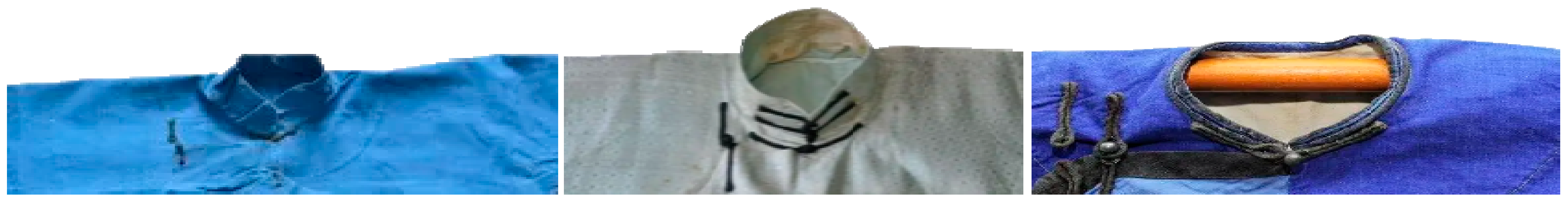
An automated 3D clothing scanning system was built in the experiment. The system includes four modules, namely a user control platform, three-dimensional image acquisition module, rotating support module, and power control output module. The stand-alone surround scanning system module is shown in Figure 3.
As shown in Figure 3, the user control platform includes an image display interface, a three-dimensional point cloud optimization panel, and a motor control panel. The image display interface is used to display the depth image captured by the 3D camera in real time, and the 3D point cloud generated by the depth image after scanning is completed. The 3D point cloud optimization panel is used to discharge point cloud optimization buttons, and the motor control panel is used to discharge motor parameter control buttons. The power control output module includes power supply, transmission bearing, motor controller, motor driver, and stepper motor. The power supply provides rotational power for the stepper motor; the transmission bearing is used to transmit the rotational force of the stepper motor; the motor controller is used to receive the motor control signal from the user control interface; the motor driver is used to convert the digital signal into a pulse signal and send it to the stepper motor. The rotation support module includes a support member, a rotation member, and a three-dimensional camera angle adjustment member. The support structure is used to provide a support frame, carrying the rotating member and the power take-off module. The rotation component is used to rotate the 3D camera and adjust the camera’s position, viewing angle, and provide a stable rotation support. The 3D image acquisition module includes a 3D scanner and an offline 3D point cloud generation algorithm.

4.1.2. Scanning Effect

In order to verify the scanning speed of the single-machine scanning system and the quality of the scanned point cloud, different garments were scanned and packaged into 3D meshes in the experiment. The experimental platform is Windows 10 operating system, 2.6 GHz CPU, 8 GB memory, and NVIDIA GeForce GTX 650. The experiment scanned a set of clothing, including six tops, and compared the real-time point cloud generation algorithm with the offline point cloud generation algorithm. The scanning devices used were all PrimeSense 1.09, which revolved around the garment under a stand-alone wrap-around mechanism. By setting the rotation speed of the rotating motor, the time that the 3D scanning camera surrounds the garment is adjusted, as shown in Table 1.
As shown in Table 1, the offline point cloud generation algorithm can generate the 3D clothing point cloud that meets the requirements within 12 s, while the real-time point cloud generation algorithm takes 35 s to generate the 3D clothing point cloud that meets the requirements. This article takes the average of three measurements for each piece of clothing. Most of the clothing grid errors generated by offline point cloud calculation and real-time point cloud algorithm are within 0.5 cm, the relative error of the experiment varies between ±2% and ±0.2%, and the root mean square error (RMSE) range does not exceed 2, which proves that the proposed offline point cloud generation algorithm is better than the real-time point cloud generation algorithm in the single-machine rotating mechanism. Under the stable and uniform rotation of the single-machine rotating mechanism, the scanned three-dimensional clothing has a similar effect, but the speed is dominant.
In order to verify the accuracy of the single-machine scanning system, six pieces of 3D clothing were measured, and the absolute difference was calculated with the actual clothing, as shown in Figure 4.
As can be seen from Figure 4, the difference is about 1 cm. According to “GB/T 2660-2017: Shirts” for the measurement position and measurement method of shirt specification determination, this error is within the allowable error range of the main part specification. The smaller scanning error provided a guarantee for the acquisition of accurate data of the 3D clothing, so that the scanned 3D clothing can keep the size of the original clothing.

4.2. Mesh Division and Grouping

After scanning a 3D garment object with a single-machine surround system and generating an initial 3D garment mesh, the surface topology needs to be trimmed and edited to form a 3D garment that can be used to simulate wearing. One of the most important operations is the cutting and separation of 3D meshes. Through the study of the 3D mesh segmentation algorithm, the connection of the cutting planes is used to generate the connected cutting intersection lines, and then the cutting intersection lines are screened, connected, and sorted to obtain the cutting path from the starting point to the end point. Through the positional relationship between the cutting path and the triangle, the segmentation forms of the triangle are classified into three categories, and finally the free cutting is completed.
In order to verify the reliability and efficiency of the cutting algorithm in this paper, the experiment of trimming and editing the surface topology of the initial 3D clothing mesh was carried out, and the generation time and the number of trimmed triangles and clothing meshes were recorded, as shown in Table 2.
As shown in Table 2, in order to verify the efficiency of the proposed 3D mesh cutting algorithm, the generation of mesh cutting lines for six 3D scanned garments and the calculation time of triangle cutting were recorded. The time used was about 0.1 s, which proved that the cutting and grouping algorithm in this chapter can be completed quickly and efficiently.
The physical images of a, b, c, d, e, and f are shown in Figure 5.

4.3. Human Body Ring Cutting Algorithm

The 3D human body ring cutting algorithm refers to an algorithm that uses a plane to intersect with a 3D human body mesh, connects and sorts the intersection points, obtains a closed ring cutting ring, and analyzes the closed ring cutting ring to obtain 3D human body information. It converts the 3D human body features into ring cutting features, and can define different intersection planes and obtain different body information. If the horizontal plane is defined and intersected with the 3D human body grid, the limb information can be analyzed according to the number of closed cut rings. The vertical section defined by the armpit point is intersected with the 3D human mesh to obtain the separation information of the human arm and torso. The intersection of the plane passing through the feature points of the human body and the three-dimensional human body grid are defined, and the measurement information of the girth of the human body is obtained. After the 3D clothing is worn on the 3D human body, the loop cutting algorithm can be used to detect the penetration information of the clothing mesh and the human body mesh by whether the cutting loops of the same layer intersect.
After optimizing the human body ring segmentation algorithm, it is used in the search of human feature points and the automatic measurement of 3D human body to verify the effectiveness of the method. At the same time, when dealing with three-dimensional clothing, this method can also be used to determine the feature points of clothing.
To confirm the precision and effectiveness of extracting human body feature points and conducting 3D body measurements using the ring cutting algorithm presented in this paper, we conducted a series of experiments as outlined below.
By comparing the automatic measurements of 200 3D scanned human bodies with the manual measurements of the corresponding human bodies, the measurement errors shown are shown in Figure 6.
As can be seen from Figure 6, most of the measurement errors are within 0.5 cm. The contact-type crotch bottom measurement error is large, because the manual measurement values of the legs are approximate. In the process of actually measuring the 3D scanning human body data, due to the large difference in leg shape, the scanned 3D human body will also have adhesion phenomenon, and there are also many parts of the human body that are difficult to automatically measure accurately by scanning the human body, such as waist circumference. Although these have an impact on the algorithm of this paper, the error is still within the acceptable range. Table 3 shows the time used by the anthropometric algorithm in this paper for anthropometric measurements of different densities.
It can be seen from Table 3 that the 3D scanning of the human body with 20 K triangles takes between 1.7 and 2.0 s. The usage time is also within 7 s in the case of 100 K triangles. In the experiment, the automatic cutting time of the test 3D clothing was recorded, as shown in Figure 7 (the horizontal axis represents five sets of cut objects (due to the extreme similarity between cropped objects f and d, e, this article will exclude f from the research object in the following experiment), the left side of the vertical axis represents the height of the bar chart, representing the clothing grid number, and the right side of the vertical axis represents the numbers for auto cutting of dashed lines and seam generation).
As can be seen in Figure 7, the automatic 3D virtual clothing cutting generation algorithm in this paper can quickly complete the generation of 3D pieces and generate sutures between pieces. For the flattening of the pieces, we compared the change of the side length L and L’ (L is the length of the triangle before flattening; L’ is the length of the triangle after flattening), as shown in Table 4.
It can be seen from Table 4 that the variation of side length is around 3%, which can keep the original information of clothing. After the three-dimensional clothing pieces are matched with the three-dimensional human body posture, gaps will be generated between the three-dimensional clothing pieces due to the movement of relative positions. It is necessary to sew the gaps between the pieces according to the seam information between the pieces of the three-dimensional garment. Figure 8 shows the corresponding segmentation of clothing in 2D and tops in 3D. (Figure 8 is made of the platform on CORELDRAW.)
As shown in Figure 8, for clothing without wrinkles, the obtained three-dimensional coordinates can be directly used. For garments with rich folds, it is a little more complicated to obtain three-dimensional coordinates, and the triangle endpoints at both ends of the seam need to be displaced during sewing. At the same time, the triangles at both ends of the seam line are merged, so that the three-dimensional garment pieces are re-merged into a whole. When merging triangle boundary points, it is necessary to ensure the smooth movement of adjacent triangle vertices to maintain the geometric characteristics of 3D clothing.

4.4. Human Body Automatic Cutting Effect

In the 3D human body automatic segmentation algorithm, the first thing is to correctly find the human body feature points corresponding to the automatically tailored clothing. For different body types, this work can be completed quickly and accurately by using the ring-cut structure and the optimization algorithm proposed in this paper. As can be seen, using the 3D human body segmentation algorithm proposed in this paper, the cutting and grouping can be well completed. When performing 3D human body segmentation, we recorded the segmentation time as shown in Table 5.
It can be seen from Table 5 that when the number of body meshes reaches 12,000, the 3D human body cutting time is only 0.72 s. Therefore, the algorithm proposed in this paper can quickly segment the 3D human body according to different 3D clothing types.

4.5. Garment Automatic Simulation Dressing Method Based on Geometric Reconstruction

On the basis of automatic 3D clothing cutting and 3D human body segmentation, an automatic 3D clothing simulation dressing method based on geometric reconstruction was proposed. In this method, the wearing of the 3D virtual clothing was completed via matching and stitching the 3D clothing pieces and the corresponding 3D human body segments. Through the three-dimensional clothing pieces and the corresponding three-dimensional human body blocks, the penetration detection of the pieces was carried out. The penetrating mesh face was detected by the ring cutting algorithm, and the mesh penetration was corrected by mesh subdivision and moving the penetrating mesh in the specified direction using the Laplace transform. These targeted pose matching methods and penetration compensation methods accelerate the wearing speed of 3D clothing. The penetration of the 3D virtual top is shown in Figure 9.
As shown in Figure 9, the method based on geometric reconstruction can keep the original geometric features of 3D virtual clothing to the maximum extent, such as drape and wrinkles, which provided a good initial state for the physical method of 3D clothing wearing. In addition, because the physical drape and wrinkle simulation are omitted, it saved time and provided a fast method for the wearing evaluation of 3D clothing. Collision detection is an important processing step after wearing 3D clothing. After the pieces of the 3D garment in this chapter have been sewn together, the penetrating garment mesh needs to be found and moved to the correct position.
The 3D clothing simulation wearing algorithm based on geometric reconstruction mainly solved the problem of pose matching between 3D clothing and human body, penetration compensation, and maintaining the geometric features of 3D clothing during wearing. In this paper, the following groups of experiments are used to verify the applicability and reliability of the algorithm in this chapter. In order to verify the dimensional stability of the 3D clothing, the area of the 3D mesh before and after wearing the clothing was compared in the experiment, as shown in Table 6.
It can be seen from Table 6 that the area change of the three-dimensional clothing is within 1.7% after being worn by the method in this paper, and the inherent size of the clothing is well maintained. In order to verify the applicability of the algorithm in this paper, experiments were carried out on different human bodies and different clothing to simulate wearing. The 3D virtual stitching is shown in Figure 10. (The 3D simulation stitching was completed on CAD.)
As shown in Figure 10, the method we used was to automatically wear the 3D clothing first, and then use the physical method to simulate the effect of the clothing. After geometric stitching and penetration compensation, the initial state of the generated physical model can retain the geometric characteristics of the 3D-scanned clothing, and the wearing effect is more realistic. Automatic dressing provided a practical and reliable method. In order to verify the efficiency of the algorithm, the wearing time of the 3D clothing was recorded in the experiment, and the simulated wearing time of the 3D clothing is shown in Figure 11.
As shown in Figure 11, the wearing time of a single 3D garment is about 10 s, which is within an acceptable range. The 3D clothing simulation dressing algorithm proposed in this paper has good applicability and can simulate 3D clothing for different human bodies, and provided a practical and reliable method for the automatic wearing of 3D clothing.

5. Conclusions

In a digital teaching approach, we have introduced “virtual simulation” technology into the process of nurturing talent in the fashion industry. The virtual simulation experimental platform for clothing product design utilizes virtual simulation technology to achieve changes in the design of prototype paper structures. We have combined three-dimensional models to reflect structural changes on the human body model, and which can design clothing structures based on real-world requirements. Based on digital design technology, this paper developed a 3D scanning garment generation and editing system based on digital design technology and careful observation of physical objects and from the simulation application requirements of 3D clothing. A three-dimensional garment automatic simulation method based on geometric reconstruction was proposed. In this study, we have put forward a fast scanning method for offline point cloud generation, and have introduced a free cutting, grouping, and seam generation algorithm for three-dimensional virtual clothing.
The application research of three-dimensional automatic human body segmentation and three-dimensional automatic garment cutting was carried out, and a complete technical route of 3D scanning garment simulation application based on geometric modeling was formed. In the experiment, the fastest cutting time for seam generation was 0.37 s for group A, and 0.18 s for group A for the fastest thing to be automatically cut.
This study has found that the drawing of clothing structures and patterns can truly and effectively restore the physical shape of traditional clothing, and has identified the key and difficult points in achieving virtual simulation design effects through pattern and traditional process modeling. The method proposed in this article is an effective method for quickly restoring the simulation of traditional folk clothing, laying the foundation for the digital display design of traditional folk clothing.

Author Contributions

Q.Y. was responsible for the manuscript writing, research framework design, mode creation, and data analysis. G.Z. was responsible for the cording and liaising as part of the research project, organization research data, proofreading language, and processing images. All authors have read and agreed to the published version of the manuscript.

Funding

This research received no external funding.

Data Availability Statement

The data used to support the findings of this study are available from the corresponding author upon request.

Conflicts of Interest

The authors declare no conflict of interest.

References

  1. Ibaydullaev, T. A study of national clothes and games as an individual part of cultural heritage. ACADEMICIA Int. Multidiscip. Res. J. 2022, 12, 13–15. [Google Scholar] [CrossRef]
  2. Hu, R.; Li, T.; Qin, Y. Ethnobotanical study on plants used to dye traditional costumes by the Baiku Yao nationality of China. J. Ethnobiol. Ethnomedicine 2022, 18, 2. [Google Scholar] [CrossRef]
  3. Pietroni, E.; Ferdani, D. Virtual restoration and virtual reconstruction in cultural heritage: Terminology, methodologies, visual representation techniques and cognitive models. Information 2021, 12, 167. [Google Scholar] [CrossRef]
  4. Hong, Y.; Bruniaux, P.; Zeng, X.; Liu, K.; Chen, Y.; Dong, M. Virtual Reality Based Collaborative Design Method for Designing Customized Garment of Disabled People with Scoliosis. Int. J. Cloth. Sci. Technol. 2017, 29, 226–237. [Google Scholar] [CrossRef]
  5. Michelinakis, G.; Nikolidakis, D.; Apostolakis, D. Complete Digital Restoration: Implant-Supported Prosthesis Using Rapid Prototyping and a Model-Free Approach. Compend. Contin. Educ. Gen. Dent. 2021, 42, 182–186. [Google Scholar]
  6. Guo, D.; Shang, S.Y. Research on Exhibition Model of Virtual Museum Based on Unity3D. J. Beijing Inst. Cloth. Technol. (Nat. Sci. Ed.) 2017, 37, 63–68. [Google Scholar]
  7. Hu, S.; Wang, R.; Zhou, F. An efficient multi-layer garment virtual fitting algorithm based on the geometric method. Int. J. Cloth. Sci. Technol. 2017, 29, 25–38. [Google Scholar] [CrossRef]
  8. Liu, K.; Zeng, X.; Bruniaux, P.; Wang, J.; Kamalha, E.; Tao, X. Fit evaluation of virtual garment try-on by learning from digital pressure data. Knowl.-Based Syst. 2017, 133, 174–182. [Google Scholar] [CrossRef]
  9. Hong, W.J.; Miao, Y.; Shen, L. Virtual Simulation Design of Traditional Chinese Folk Double-Breasted Robes Based on 3D Modeling Technology. J. Beijing Inst. Cloth. Technol. (Nat. Sci. Ed.) 2018, 38, 52–58. [Google Scholar]
  10. Stroia, R.I.; Popescu, P.G. Jewelry box and cigarette case: Description, investigation, restoration. Brukenthal Acta Musei 2017, 12, 635–644. [Google Scholar]
  11. Chen, T.; Yang, E.K.; Lee, Y. Development of virtual up-cycling fashion design based on 3-dimensional digital clothing technology. Res. J. Costume Cult. 2021, 29, 374–387. [Google Scholar] [CrossRef]
  12. Wang, Z.; Wang, J.; Zeng, X.; Sharma, S.; Xing, Y.; Xu, S.; Liu, L. Prediction of garment fit level in 3D virtual environment based on artificial neural networks. Text. Res. J. 2021, 91, 1713–1731. [Google Scholar] [CrossRef]
  13. Wu, Y.; Jiang, Q.; Liang, H.; Ni, S.Y. What Drives Users to Adopt a Digital Museum? A Case of Virtual Exhibition Hall of National Costume Museum. SAGE Open 2022, 12, 729–736. [Google Scholar] [CrossRef]
  14. Sci, Z. Virtual Clothing Display Platform Based on CLO3D and Evaluation of Fit. J. Fiber Bioeng. Inform. 2020, 13, 37–49. [Google Scholar] [CrossRef]
  15. Zhang, J.; Zeng, X.; Liu, K.; Yan, H.; Dong, M. Jeans knowledge base development based on sensory evaluation technology for customers’ personalized recommendation. Int. J. Cloth. Sci. Technol. 2018, 30, 101–111. [Google Scholar] [CrossRef]
  16. Santesteban, I.; Otaduy, M.A.; Dan, C. Learning ased Animation of Clothing for Virtual Try. Comput. Graph. Forum 2019, 38, 355–366. [Google Scholar] [CrossRef]
  17. Ma, Q.; Yang, J.; Tang, S.; Black, M.J. The power of points for modeling humans in clothing. In Proceedings of the IEEE/CVF International Conference on Computer Vision, Montreal, QC, Canada, 10–17 October 2021; pp. 10974–10984. [Google Scholar]
  18. Na, R.B.; Koo, S. Wearable Designs for Hair Designers with 3D Virtual Images and 3D Printed Models. J. Korean Soc. Cloth. Text. 2020, 44, 923–949. [Google Scholar]
  19. Jang, H.; Chen, J. A study on 3D virtual body formation and deformation by body shape analysis. Int. J. Cloth. Sci. Technol. 2019, 31, 755–776. [Google Scholar] [CrossRef]
  20. Wu, G.; Li, D.; Zhong, Y. A study on improving the calibration of body scanner built on multiple RGB-Depth cameras. Int. J. Cloth. Sci. Technol. 2017, 29, 314–329. [Google Scholar] [CrossRef]
  21. Lage, A.; Ancutiene, K. Virtual try-on technologies in the clothing industry: Basic block pattern modification. Int. J. Cloth. Sci. Technol. 2019, 31, 729–740. [Google Scholar] [CrossRef]
  22. Zhao, W.; Zhou, Y.K.; Zhang, H. Amenity Design for the Shoulder and Back of Combat Uniform Based on 3D Virtual Fitting System. J. Beijing Inst. Cloth. Technol. (Nat. Sci. Ed.) 2017, 37, 40–48. [Google Scholar]
Figure 1. A diagram of the Hakka cardigan style.
Electronics 12 04190 g001
Figure 2. Hakka cardigan collar.
Electronics 12 04190 g002
Figure 3. Stand-alone surround-scanning system module.
Electronics 12 04190 g003
Figure 4. Absolute difference between 3D scanned garment size and actual garment measurement.
Electronics 12 04190 g004
Figure 5. (af) Six sets of physical images of cropped objects.
Electronics 12 04190 g005
Figure 6. Absolute value mean error (cm).
Electronics 12 04190 g006
Figure 7. 3D garment automatic cutting time record.
Electronics 12 04190 g007
Figure 8. Clothing 2D tops wearing 3D correspondence segmentation. (a) Display of clothing marking parts; (b) Restoration of clothing model after 2D coordinates are converted to 3D.
Electronics 12 04190 g008
Figure 9. Penetration of 3D virtual tops. (a) Penetrating mesh surface at different parts. (b) Ring cutting at different parts after compensation.
Electronics 12 04190 g009
Figure 10. Three-dimensional virtual stitching.
Electronics 12 04190 g010
Figure 11. 3D clothing simulation wearing time.
Electronics 12 04190 g011
Table 1. Comparison of point cloud generation algorithms.
InstructionsReal-Time Point Cloud Generation AlgorithmOffline Point Cloud Generation Algorithm
One rotation time35 (s)12 (s)
Average point cloud generation time0.07 (s)10 (s)
Average frame rate15 (fps)30 (fps)
Average number of generated depth images500 (px)390 (px)
Table 2. Triangle segmentation time information records of tailored garments.
Cut ObjectClipping Time (s)Number of Cut TrianglesNumber of Clothing Grids
a0.1267812,000
b0.1047310,560
c0.1374015,000
d0.1232012,300
e0.1042010,200
f0.1238413,000
Table 3. Using time of 3D anthropometric measurements with different densities.
Number of Triangular Mesh Faces (K)Use Time (s)
201.7
402.7
603.6
804.1
1006.1
Table 4. Average absolute deviation of triangle edges before and after flattening of 3D pieces.
Number of SidesMean Absolute Deviation
12,7110.021
96510.039
17,4300.034
Table 5. Three-dimensional human body cutting time.
Number of Body MeshesAuto Split Time (s)
80110.44
82000.46
85030.47
10,3000.61
12,0000.72
Table 6. Area comparison of the three-dimensional clothing mesh after wearing and the original clothing mesh.
Area (cm)Change Rate (%)
Original clothing grid122.220
a123.471.02%
b124.261.67%
c123.380.95%
d123.841.32%
e124.151.57%
Disclaimer/Publisher’s Note: The statements, opinions and data contained in all publications are solely those of the individual author(s) and contributor(s) and not of MDPI and/or the editor(s). MDPI and/or the editor(s) disclaim responsibility for any injury to people or property resulting from any ideas, methods, instructions or products referred to in the content.

