


SHDL—A Hardware Description Language and Open-Source Web Tool for Online Digital Systems Design Teaching

Abstract
:1. Introduction
- instance—an instantiation of a circuit component;
- assignment—describes combinational data flow;
- sequential block (e.g., conditional assignments) for algorithmic behavioral specification.

- presentation of the improved SHDL syntax and SHDL web tool;
- introduction of an online teaching model for the DESD course, using the SHDL tool;
- evaluation of the SHDL web tool, in relation to the knowledge output of the online teaching model;
- discussion of the online teaching model and learning experience.
2. Hardware Description Learning Tools
Existing Digital Design Languages and Tools
3. Proposed Methodology
3.1. Small Hardware Description Language
| circuit :== [‘entity’ name] {declarations} [‘begin’] block [‘end’] declarations :== declaration {[;] declaration} declaration :== name_list ‘:’ [mode] type [= value] mode :== ‘in’ | ‘out’ name_list :== identifier {, identifier} block :== statement {[;] statement} statement :== assign | cond_as | if_stat | instance |
| a,b: in u1 /* 1-bit input ports */ c : out u4 /* 4-bit unsigned output port */ d : s8 /* 8-bit signed internal signal */ q : u2 = 1 /* 2-bit signal with initial value 1 */ |
| state: (idle, run, stop); |
| assign :== identifier as_op expression as_op :== ‘=‘ | ‘<=‘ cond_as :== identifier as_op expression ‘when’ condition ‘else’ expression |
- parenthesis: (, )
- vector slicing: name(index), name(high downto low)
- unary: -, not
- multiply: *
- arithmetic: +,− and concatenate: &
- relational: =, /=, >, >=, <, <=
- logic: and , or, xor, nand, nor
| if_stat :== ‘if’ condition ‘then’ block {‘elsif’ condition ‘then’ block} [‘else’ block] ‘end’ |
| instance :== identifier ‘(‘ name_list ‘)’ |
3.2. SHDL Compared to VHDL
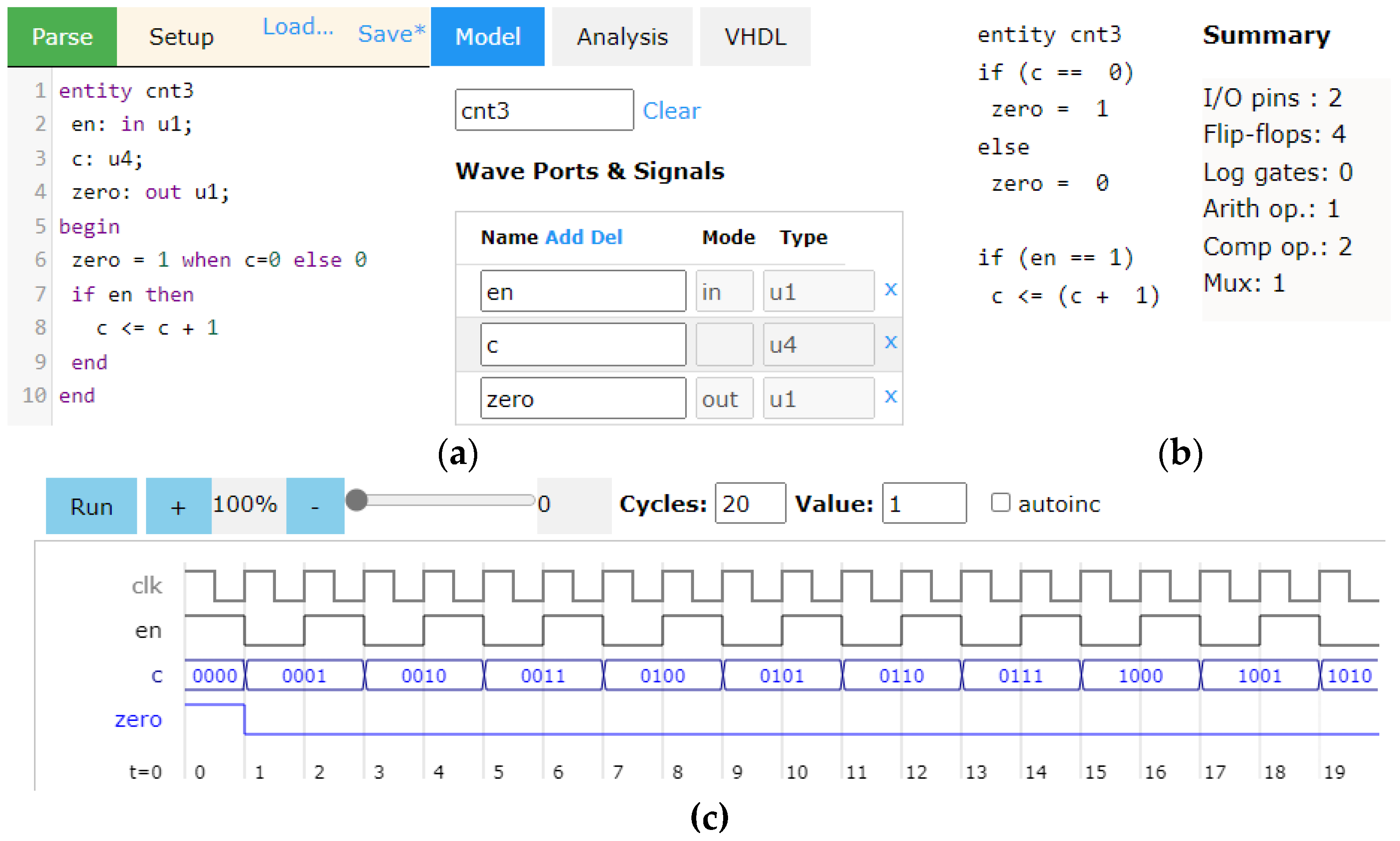
3.3. Open-Source SHDL Web-Based Tool
- the SHDL code editor with syntax coloring;
- code parser and circuit analysis;
- circuit model simulator, waveform viewer, board simulator;
- generator for readable VHDL code with test bench;
- PHP extension for saving models to a server, and support for teachers.
4. Teaching with SHDL Web Tool
4.1. Online Teaching Model
4.2. Introductory Examples

| (a) | (b) | ||
| 1 | entity bindec2 | 1 | entity bindec2 is |
| 2 | a: in u2; | 2 | port (a: in unsigned(1 downto 0); |
| 3 | y: out u4; | 3 | y: out unsigned(3 downto 0)); |
| 4 | table: 4u4 = 1,2,4,8; | 4 | end bindec2; |
| 5 | begin | 5 | architecture RTL of bindec2 is |
| 6 | y = table(a) | 6 | type table_type is array (0 to 3) of unsigned(3 downto 0); |
| 7 | end | 7 | constant table : table_type := (“0001”, “0010”, “0100”, “1000”); |
| 8 | begin | ||
| 9 | y <= table(to_integer(a)); | ||
| 10 | end RTL; | ||
| 1 | c: u4 = “0001”; | 1 | constant c: unsigned(3 downto 0) := “0001”; |
| 2 | y = c sll a | 2 | y <= shift_left(c, to_integer(a)); |
| 1 | valid = 1 | 1 | process(d) |
| 2 | if d(1)=1 then | 2 | begin |
| 3 | code = 1 | 3 | valid <= ‘1’; |
| 4 | elsif d(0)=1 then | 4 | if d(1) = ‘1’ then |
| 5 | code = 0 | 5 | code <= to_unsigned(1, 2); |
| 6 | else | 6 | elsif d(0) = ‘1’ then |
| 7 | code = 0 | 7 | code <= to_unsigned(0, 2); |
| 8 | valid = 0 | 8 | else |
| 9 | end | 9 | code <= to_unsigned(0, 2); |
| 10 | valid <= ‘0’; | ||
| 11 | end if; | ||
| 12 | end process; |
| (a) | (b) | (c) | |||
| 1 | entity mux | 1 | entity mux | 1 | entity mux |
| 2 | data: in u8 | 2 | data: in u8 | 2 | data: in u8 |
| 3 | en: in u1 | 3 | en: in u1 | 3 | en: in u1 |
| 4 | sel: in u3 | 4 | sel: in u3; | 4 | sel: in u3; |
| 5 | z: out u1 | 5 | z: out u1; | 5 | z: out u1; |
| 6 | begin | 6 | begin | 6 | begin |
| 7 | if en then | 7 | z = data(sel) | 7 | z = 0 |
| 8 | z = data(sel) | 8 | if en=0 then | 8 | if en then |
| 9 | else | 9 | z = 0 | 9 | z = data(sel) |
| 10 | z = 0 end | 10 | end | 10 | end |
| 11 | end | end | end |
| (a) SHDL—wrong | (b) SHDL | (c) VHDL | |||
| 1 | if set then | 1 | if set then | 1 | process(set,en,data) |
| 2 | z = 1 | 2 | z = 1 | 2 | begin |
| 3 | end | 3 | elsif en then | 3 | if set = ‘1’ then |
| 4 | if en then | 4 | z = data(sel) | 4 | z <= ‘1’; |
| 5 | z = data(sel) | 5 | else | 5 | elsif en = ‘1’ then |
| 6 | else | 6 | z = 0 end | 6 | z <= data(to_integer(sel)); |
| 7 | z = 0 end | 7 | end | 7 | else |
| 8 | end | 8 | 8 | z <= ‘0’; | |
| 9 | 9 | 9 | end if; | ||
| 10 | 10 | 10 | end process; | ||
| (a) | (b) | (c) | |||
| 1 | if load then | 1 | if load then | 1 | architecture RTL of shiftreg2 is |
| 2 | q <= d; | 2 | q <= d; | 2 | signal q: unsigned(3 downto 0): = “0000”; |
| 3 | else | 3 | else | 3 | begin |
| 4 | q(0) <= q(1); | 4 | q <= sin & q(3 downto 1) | 4 | process(clk) |
| 5 | q(1) <= q(2); | 5 | end | 5 | begin |
| 6 | q(2) <= q(3); | 6 | sout = q(0) | 6 | if rising_edge(clk) then |
| 7 | q(3) <= 0; | 7 | if load = ‘1’ then | ||
| 8 | end | 8 | q <= d; | ||
| 9 | sout = q(0) | 9 | else | ||
| 10 | q <= sin & q(3 downto 1); | ||||
| 11 | end if; | ||||
| 12 | end if; | ||||
| 13 | end process; | ||||
| 14 | sout <= q(0); | ||||
| 15 | end RTL; | ||||
4.3. Online Teaching Model Exercises Activities Delivery
- use logic building blocks in digital systems;
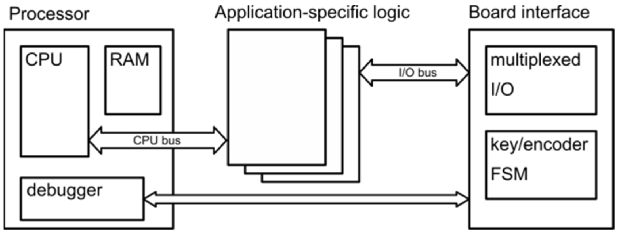
- understand digital system components, HW/SW task division, and design process;
- implement and analyze digital HDL models on RTL, behavioral, and structural levels;
- write an HDL model of a simple CPU, following the specifications, and produce test assembly code;
- develop a small digital system implemented by a programmable device.
4.3.1. Mini-Project
| 1 | entity micro | 31 | entity program |
| 2 | reset: in u1 | 32 | adr: in u8 |
| 3 | acum: out u12 | 33 | data: out u12 |
| 4 | st: (fetch, exec) | 34 | we: in u1 |
| 5 | adr, adr1, pc: u8; | 35 | din: in u12 |
| 6 | we: u1; | 36 | rom: 16u12 = x”104”, -- LDA 05 |
| 7 | data: u12; | 37 | x”805”, -- ADD 06 |
| 8 | inst: u4; | 38 | x”204”, -- STA 05 |
| 9 | LDA: u4=1; STA: u4=2; JMP: u4=4; ADD: u4=8 | 39 | x”400”, -- JMP 01 |
| 10 | begin | 40 | x”003”, |
| 11 | adr = adr1 when st=exec else pc | 41 | x”001”; |
| 12 | we = 1 when st=exec and inst=STA else 0 | 42 | begin |
| 13 | program(adr, data, we, acum) | 43 | data=rom(adr); |
| 14 | 44 | if we then | |
| 15 | if st=fetch and reset=0 then | 45 | rom(adr)<=din |
| 16 | st <= exec | 46 | end |
| 17 | pc <= pc + 1 | 47 | end |
| 18 | adr1 <= data(7 downto 0) | ||
| 19 | inst <= data(11 downto 8) | ||
| 20 | else | ||
| 21 | st <= fetch | ||
| 22 | if inst=LDA then | ||
| 23 | acum <= data; | ||
| 24 | elsif inst=JMP then | ||
| 25 | pc <= adr1 | ||
| 26 | elsif inst=ADD then | ||
| 27 | acum <= acum + data; | ||
| 28 | end | ||
| 29 | end | ||
| 30 | end |
4.3.2. Final Project
- animation or simple electronic game on VGA monitor or graphical matrix display;
- electronic music instrument playing notes from keyboard or saved music;
- digital function generator with pulse-width modulated output.
5. DESD Online Teaching Model Evaluation and Discussion
Method
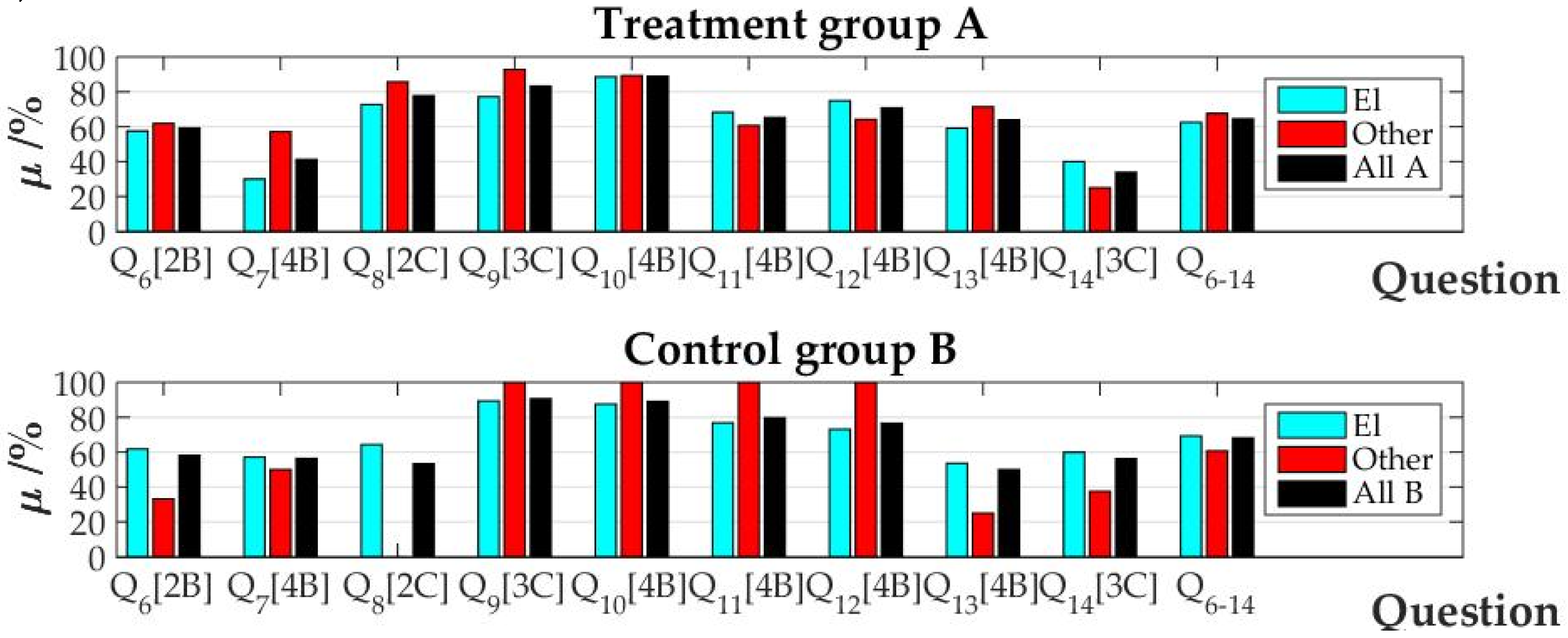
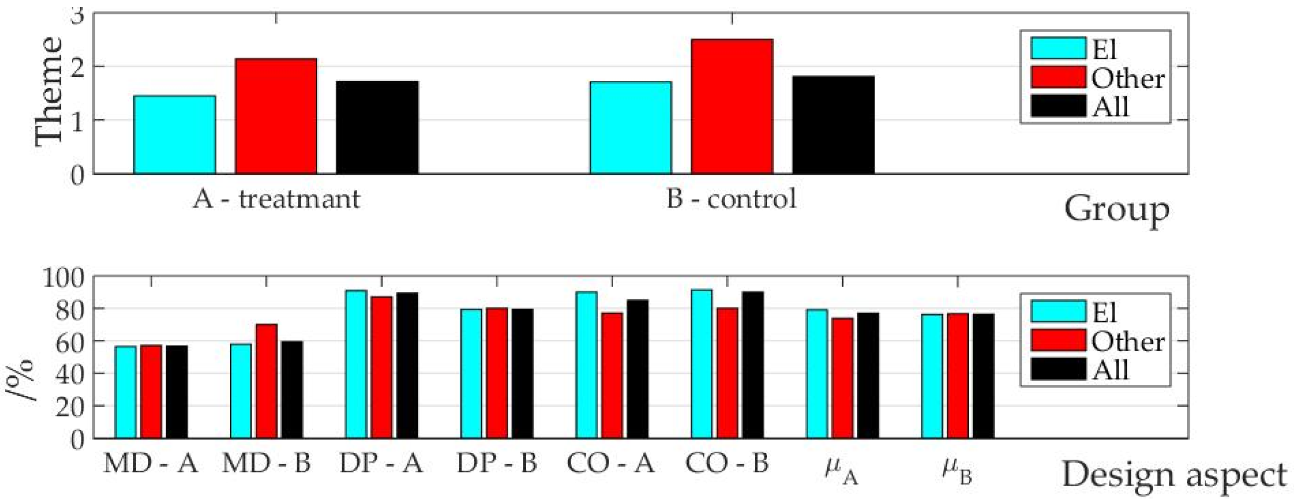
6. Results
7. Discussion
8. Conclusions
Author Contributions
Funding
Institutional Review Board Statement
Data Availability Statement
Conflicts of Interest
References
- Mano, M.M.R.; Ciletti, M.D. Digital Design, Global Edition; Pearson Education Limited: Harlow, UK, 2018. [Google Scholar]
- Ochoa, H.A.; Shirvaikar, M.V. A Survey of Digital Systems Curriculum and Pedagogy in Electrical and Computer Engineering Programs. In Proceedings of the ASEE Gulf-Southwest Section Annual Conference, Austin, TX, USA, 4–6 April 2018. [Google Scholar] [CrossRef]
- Del Sozzo, E.; Conficconi, D.; Zeni, A.; Salaris, M.; Sciuto, D.; Santambrogio, M.D. Pushing the Level of Abstraction of Digital System Design: A Survey on How to Program FPGAs. ACM Comput. Surv. 2022, 55, 1–48. [Google Scholar] [CrossRef]
- Nelson, I.; Ferreira, R.; Nacif, J.A.; Jamieson, P. Is It Time to Include High-Level Synthesis Design in Digital System Education for Undergraduate Computer Engineers? In Proceedings of the 2021 IEEE International Symposium on Circuits and Systems (ISCAS), Virtual, 22–28 May 2021; pp. 1–5. [Google Scholar] [CrossRef]
- Graña, C.Q.; Rodríguez, J.F.; Rodríguez-Andina, J.J. Hands-On Learning of Digital Systems Through Semi-Guided Projects. IEEE Rev. Iberoam. Tecnol. Aprendiz. 2017, 12, 132–140. [Google Scholar] [CrossRef]
- Ismahani, I.; Paraman, N.; Zabidi, M.; Mohd-Yusof, K. Implementation of Active Learning in Digital Systems Course. AIP Conf. Proc. 2022, 2433, 030009. [Google Scholar] [CrossRef]
- Skliarova, I. Project-Based Learning and Evaluation in an Online Digital Design Course. Electronics 2021, 10, 646. [Google Scholar] [CrossRef]
- Becker, K. A web based tool for teaching hardware design based on the plain simple hardware description language. In Proceedings of the EDUCON, Istanbul, Turkey, 3–5 April 2014. [Google Scholar] [CrossRef]
- Trost, A.; Žemva, A. A web-based tool for learning digital circuit high-level modeling. Int. J. Eng. Educ. 2019, 35, 1224–1237. [Google Scholar]
- Dally, W.J.; Harting, R.C.; Aamodt, T.M. Digital Design Using VHDL; Cambridge University Press: Cambridge, UK, 2016. [Google Scholar]
- Jansen, J. Changes and continuities in South Africa’s higher education system, 1994 to 2004. In Changing Class: Education and Social Change in Postapartheid South Africa; Chisholm, L., Ed.; Oxford University Press Southern Africa: Cape Town, South Africa, 2004. [Google Scholar]
- Kahiigi, E.K. Exploring the e-Learning State of Art. Electron. J. e-Learn. 2008, 6, 77–88. [Google Scholar]
- Singh, V.; Thurman, A. How many ways can we define online learning? A systematic literature review of definitions of online learning (1988–2018). Am. J. Distance Educ. 2019, 33, 289–306. [Google Scholar] [CrossRef]
- Almaiah, M.A.; Hajjej, F.; Lutfi, A.; Al-Khasawneh, A.; Shehab, R.; Al-Otaibi, S.; Alrawad, M. Explaining the Factors Affecting Students’ Attitudes to Using Online Learning (Madrasati Platform) during COVID-19. Electronics 2022, 11, 973. [Google Scholar] [CrossRef]
- Nikolic, B.; Radivojevic, Z.; Djordjevic, J.; Milutinovic, V. A Survey and Evaluation of Simulators Suitable for Teaching Courses in Computer Architecture and Organization. IEEE Trans. Educ. 2009, 52, 449–458. [Google Scholar] [CrossRef]
- Prasad, P.W.C.; Alsadoon, A.; Beg, A.; Chan, A. Incorporating simulation tools in the teaching of digital logic design. In Proceedings of the ICCSCE 2014, Penang, Malaysia, 28–30 November 2014. [Google Scholar] [CrossRef]
- Roy, G.; Ghosh, D.; Mandal, C. COLDVL: A virtual laboratory tool with novel features to support learning in logic design and computer organization. J. Comput. Educ. 2017, 4, 461–490. [Google Scholar] [CrossRef]
- Shoufan, A.; Lu, Z.; Huss, S.A. A Web-Based Visualization and Animation Platform for Digital Logic Design. IEEE Trans. Learn. Technol. 2015, 8, 225–239. [Google Scholar] [CrossRef]
- Mathumisaranon, P.C.T. MATLAB GUI for digital communication system with tone jamming. In Proceedings of the IEEE International Conference on Teaching, Assessment and Learning for Engineering (TALE), Bali, Indonesia, 26–29 August 2013. [Google Scholar] [CrossRef]
- Perales, T.; Morgan, J.; Porter, J. A Labview Fpga Toolkit To Teach Digital Logic Design. In Proceedings of the 2009 Annual Conference & Exposition, Austin, TX, USA, 14 June 2009. [Google Scholar]
- Zheng, Y.; Zheng, P. Case Teaching of Parallel FIR Digital Filter Design Combined Matlab with FPGAs. In Proceedings of the International Conference on Artificial Intelligence and Education (ICAIE), Tianjin, China, 26–28 June 2020. [Google Scholar] [CrossRef]
- Xilinx Inc. Vivado Design Suite—HLx Editions. Available online: https://www.xilinx.com//products/design-tools/vivado.html (accessed on 30 November 2022).
- Gingold, T. GHDL. 2017. Available online: http://ghdl.free.fr/ (accessed on 30 November 2022).
- Kumar, A.; Panicker, R.C.; Kassim, A. Enhancing VHDL learning through a light-weight integrated environment for development and automated checking. In Proceedings of the IEEE International Conference on Teaching, Assessment and Learning for Engineering (TALE), Bali, Indonesia, 26–29 August 2013. [Google Scholar] [CrossRef]
- Dasygenis, M. A distributed VHDL compiler and simulator accessible from the web. In Proceedings of the 24th International Workshop on Power and Timing Modeling, Optimization and Simulation (PATMOS), Palma de Mallorca, Spain, 29 September–1 October 2014. [Google Scholar] [CrossRef]
- Doulos. EDA Playground Documentation. Available online: http://www.edaplayground.com/ (accessed on 30 November 2022).
- Arvind, M. Bluespec: A Language for hardware design, simulation, synthesis and verification. In Proceedings of the MEMOCODE’03, ACM, Mont Saint-Michel, France, 24–26 June 2003. [Google Scholar] [CrossRef]
- Bachrach, J.; Vo, H.; Richards, B.; Lee, Y.; Waterman, A.; Avižienis, R.; Wawrzynek, J.; Asanović, K. Chisel: Constructing hardware in a Scala embedded language. In Proceedings of the DAC Design Automation Conference 2012, San Francisco, CA, USA, 3–7 June 2012. [Google Scholar] [CrossRef]
- Khronos OpenCL Overview. Khronos. Available online: https://www.khronos.org/opencl/ (accessed on 30 November 2022).
- Li, Y.; Leeser, M. HML, a novel hardware description language and its translation to VHDL. IEEE Trans. VLSI Syst. 2000, 8, 1–8. [Google Scholar] [CrossRef]
- Meeus, W.; Van Beeck, K.; Goedeme, T.; Meel, J.; Stroobandt, D. An overview of today’s high-level synthesis tools. Des. Autom. Embed. Syst. 2012, 16, 31–51. [Google Scholar] [CrossRef]
- Vandeportaele, B. A Finite State Machine modeling language and the associated tools allowing fast prototyping for FPGA devices. In Proceedings of the IEEE International Workshop of Electronics, Control, Measurement, Signals and their Application to Mechatronics (ECMSM), Donostia-San Sebastian, Spain, 24–26 May 2017. [Google Scholar] [CrossRef] [Green Version]
- Birleanu, F.M. CHDL1: Implementing a simplified version of the CompactHDL hardware description language. J. Electr. Eng. Electron. Control. Comput. Sci. 2018, 4, 17–22. [Google Scholar]
- Trost, A. Small Hardware Description Language. Available online: https://github.com/andrejtrost/shdl (accessed on 30 November 2022).
- Peters, O. Distance education and industrial production: A comparative interpretation in outline (1967). In Otto Peters on Distance Education: The Industrialisation of Teaching and Learning; Keegan, D., Ed.; Routledge: London, UK, 1994; pp. 107–127. [Google Scholar]
- Suryawanshi, V.; Suryawanshi, D. Fundamentals of e-learning models: A review. IOSR-JCE. Innov. Eng. Sci. Technol. (NCIEST 2015) 2015, 2, 107–120. [Google Scholar]
- Anderson, T. The Theory and Practice of Online Learning, 2nd ed.; AU Press: Montgomery, AL, USA, 2011. [Google Scholar]
- Bosch, C.; Laubscher, D.J. Promoting Self-Directed Learning as Learning Presence through Cooperative Blended Learning. Int. J. Learn. Teach. 2022, 21, 17–34. [Google Scholar] [CrossRef]
- Almaiah, M.A. Thematic analysis for classifying the main challenges and factors influencing the successful implementation of e-learning system using Nvivo. Int. J. Adv. Trends Comput. Sci. Eng. 2020, 9, 142–152. [Google Scholar] [CrossRef]
- Žemva, A.; Trost, A. Design of Custom Processors for the FPGA Devices. Elektrotehniški Vestn. 2012, 79, 55–60. [Google Scholar]
- Anderson, L.; Krathwohl, D. A Taxonomy for Learning, Teaching and Assessing: A Revision of Bloom’s Educational Objectives; Complete Edition; Longman: London, UK, 2001. [Google Scholar]


| Parameter | VHDL’93 | SHDL 3 |
|---|---|---|
| Abstraction | structural, RTL, behavioral | structural, RTL, behavioral |
| Conciseness | verbose syntax, 97 reserved words | concise syntax 17 reserved words |
| Modeling ability | combinational logic, synchronous (multiple clock), multilevel (tristate) logic | combinational logic synchronous (single clock) binary logic |
| Data type | Scalar: enumeration; integer; float; and physical. Composite: array; record access; file. | single bit, unsigned, signed, enumeration, integer one-dimensional array |
| Type conversion | explicit conv. functions, library overloading | implicit |
| Modeling hierarchy | component, process, package, function, procedure | component |
| Generic models | generic parameters | not available |
| Exercise Topic | Knowledge | Laboratory Lessons |
|---|---|---|
| 1. Combinational | HDL design flow | 2 |
| a. select, sort | dataflow model | |
| b. multiply, ALU | testbench, symbolic | |
| 2. Sequential | 2 | |
| a. LFSR | sequential HDL | |
| b. running lights | counter-usage | |
| c. FSM | symbolic HDL | |
| 3. Components | 2 | |
| a. NCO | structural HDL | |
| b. microsequencer | RTL design | |
| 4. Mini-project | 2 | |
| a. basic CPU | cycle accurate RTL | |
| b. upgraded CPU | design an IP | |
| 5. Digital system | 3–4 | |
| a. CPU IP | re-use existing IP | |
| b. interface | state machines | |
| c. display units | system timing | |
| 6. Project | develop FPGA-based digital system | 3–4 |
Disclaimer/Publisher’s Note: The statements, opinions and data contained in all publications are solely those of the individual author(s) and contributor(s) and not of MDPI and/or the editor(s). MDPI and/or the editor(s) disclaim responsibility for any injury to people or property resulting from any ideas, methods, instructions or products referred to in the content. |
© 2023 by the authors. Licensee MDPI, Basel, Switzerland. This article is an open access article distributed under the terms and conditions of the Creative Commons Attribution (CC BY) license (https://creativecommons.org/licenses/by/4.0/).
Share and Cite
Trost, A.; Jamšek, J.; Žemva, A. SHDL—A Hardware Description Language and Open-Source Web Tool for Online Digital Systems Design Teaching. Electronics 2023, 12, 425. https://doi.org/10.3390/electronics12020425
Trost A, Jamšek J, Žemva A. SHDL—A Hardware Description Language and Open-Source Web Tool for Online Digital Systems Design Teaching. Electronics. 2023; 12(2):425. https://doi.org/10.3390/electronics12020425
Chicago/Turabian StyleTrost, Andrej, Janez Jamšek, and Andrej Žemva. 2023. "SHDL—A Hardware Description Language and Open-Source Web Tool for Online Digital Systems Design Teaching" Electronics 12, no. 2: 425. https://doi.org/10.3390/electronics12020425