Article

Robust Control of SEDCM by Fuzzy-PSO

1
Department of Electrical Engineering, Trinity College of Engineering & Technology, Karimnagar 505001, India
2
Department of Data Science and Engineering, SIT, Manipal University Jaipur, Jaipur 303007, India
3
Department of Computer Science and Engineering, SCCE, Karimnagar 505527, India
4
Faculty of Electrical Engineering, Wroclaw University of Science and Technology, 50-370 Wrocław, Poland
5
Department of Electrical Power Engineering, Faculty of Electrical Engineering and Computer Science, VSB-Technical University of Ostrava, 708-00 Ostrava, Czech Republic
*
Authors to whom correspondence should be addressed.
Electronics 2023, 12(2), 335; https://doi.org/10.3390/electronics12020335
Submission received: 22 December 2022 / Revised: 4 January 2023 / Accepted: 5 January 2023 / Published: 9 January 2023
(This article belongs to the Special Issue Feature Papers in Industrial Electronics)

Abstract

:
Industries have many rotational operations that are used for design, transport, lift, drilling, rolling, robotics, and many other applications. These rotating applications require a proper controller for accurate control of the operation. Separately excited DC motors (SEDCMs) are versatile and have various industrial operations because of their specific speed control characteristics. So, for smooth and accurate operation of an SEDC motor, controllers should be used. PI and PID controllers are used in many cases, but they are ineffective for nonlinear load operation. A fuzzy controller is a heuristic controller and can provide automatic control of the operation. Its operation depends on the selection of the correct membership values. This work proposes a novel particle swarm optimization (PSO) technique that would provide the optimum value of the membership for fuzzy controllers for optimum control of the industrial processes. To obtain SEDC results, MATLAB simulation was performed, and the fuzzy controller with novel PSO was implemented. A fuzzy PSO controller used for motor speed control operation obtains a rise time of 0.00026 s, settling time of 0.000214 s, maximum overshoot of zero, and delay time of 0.016 s, which are the best values when compared to PID and PID-Fuzzy controllers. It is observed that the results obtained from the separately excited DC motor using a fuzzy PSO controller improve the dynamic behavior of the motor that so it smoothly tracks the required speed without any more overshoot or oscillation than the PID controller. Such dynamic, stable operation of the motor makes it perfect for industrial as well as household operations.

1. Introduction

SEDC motors have many important characteristics, such as wide-range operation and continuous and accurate controlling, make it versatile and useful in many industrial applications. This motor is mostly used in traction systems, steel, and rolling mills where constant and smooth operation is required, such as those of electrical vehicles, electric cranes, and robotic operations. For performing any particular task, the motor operates in various modes of speed. So, the motor requires a controller that can control the motor’s speed as per the desired application [1].
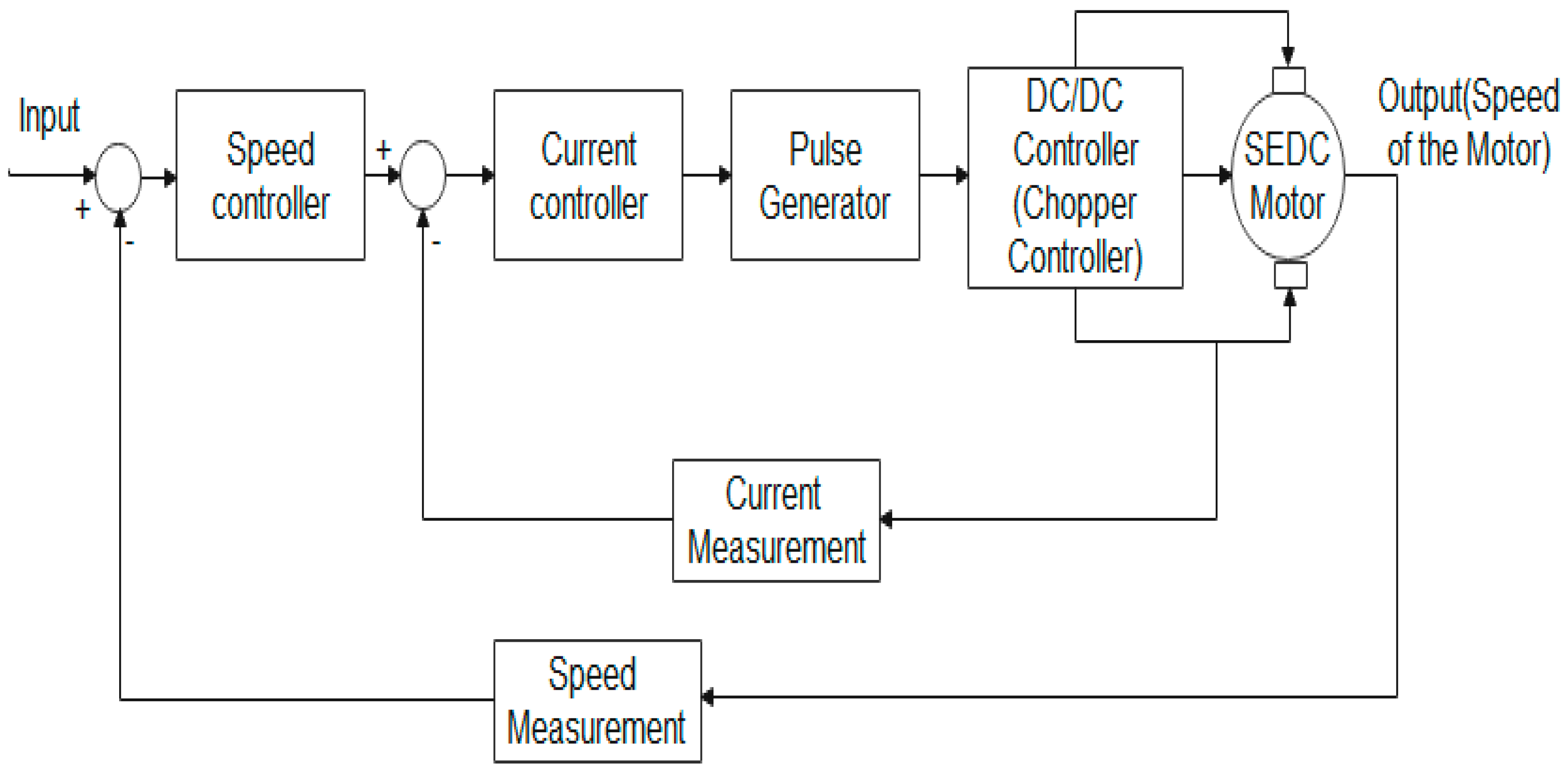
The controller’s application collects the signals from the process, determines how much speed is required, and operates the motor at the desired speed. Using a feedback system, the controller collects the information regarding the actual rotating speed at real-time operation and compares it with reference values. If the speed decreases from the required value, it takes action and increases up to the desired speed value of the motor [2].
Classical controllers have been broadly suggested for the speed control of SEDCMs. The performance of these controllers mainly depends on the accuracy of a mathematical model of the motor for different industrial applications required to develop mathematical models subjected to variation in parameters. Article [3] used chopper control, PI controller suggested [4], phase locked loop method implemented in [5], propose classical controlling method such as field weakening [6], flyback converter [7] and internal model control used by [8].
When the motor is handling the nonlinear loads, the parameters such as friction and magnetic saturation of the load change continuously. Conventional controllers cannot maintain the motor’s constant speed. Now, these controllers are replaced by artificial intelligence-based controllers for more intelligent control of the speed of SEDCMs. Researchers proposed some new controlling algorithms which are more effective than classical controllers, such as the fuzzy controller, fuzzy PI controller, and NN-fuzzy controller [9].
The fuzzy controller provides flexibility to design the controller for different motor applications using a set of fuzzy membership functions. It is very effective for the nonlinear operation of the motor and provides smooth and accurate operation. Table 1 presents the difference between FLC and conventional controllers.
Digital controllers take action only when the input is “1”, which means it is in an “ON” state for the digital controller (when the input is zero, it means it is in an “OFF” state). The fuzzy controller cannot work as a digital controller with zero and one, but it can work between zero and one. For example, imagine that someone is checking the height of the students in a class and takes a standard value such as 6 feet as the threshold for tallness, meaning that any student above 6 feet is tall and any student below 6 feet is short. If using a digital controller, when the input is 6 feet or more, it would give the result “Tall or 1”, and when the input is below 6 feet, it would give the result “Short or 0”. However, we can see that practically any student who has a height of around 5.99 feet is also tall, but the digital controller considered him or her short.
In the fuzzy controller, they are not considered tall or short, but they are assigned a membership function that is nearest to the results. The fuzzy controller creates fuzzy membership between zero and one for presenting the concepts of partial truth. In the fuzzy controller, the tallest student receives a maximum membership of “1”, and the remaining student who has less height receives a decremented membership up to zero. It implements human thinking and experience for creating a control system. Fuzzy logic is considered to be like human thinking for practical work because the system does not consist of black and white but lies in grayness [10].
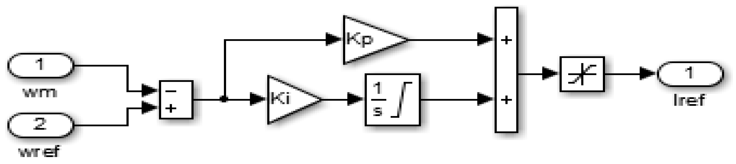
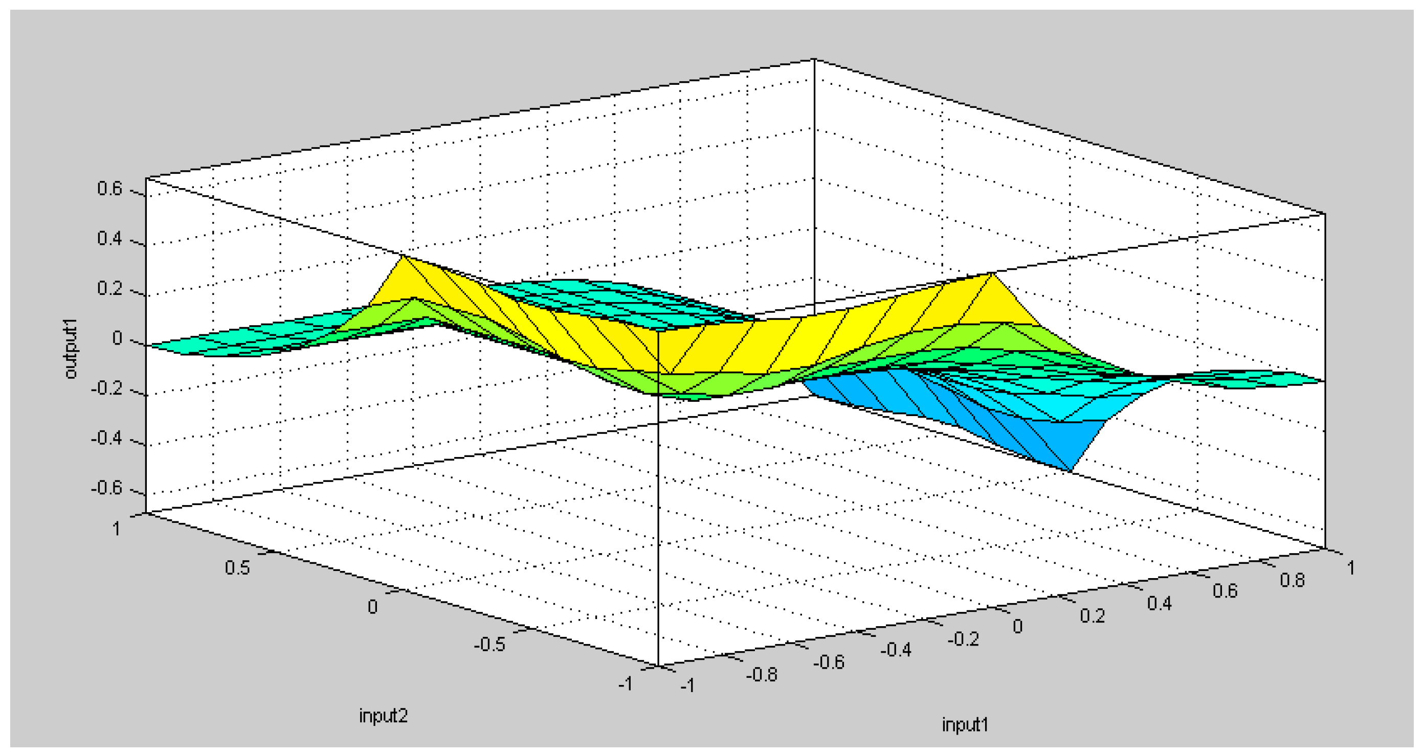
The effectiveness of the fuzzy controller can be improved if the optimum value of the selected membership functions is used. PSO is the optimization technique to determine the optimum value of a linear or nonlinear set of data. This work used a fuzzy PSO controller to obtain the optimum speed control of an SEDC motor. This controller is also effective even if the load is changing. Simulation results were obtained by the fuzzy PSO controller compared with the results obtained by the PID controller. In the results section, a deep discussion is given.

Literature Review

The following paragraphs discuss the work conducted by various researchers on the speed control of DC motors. NARMA L2 suggested speed regulation of SEDCM which can handle the nonlinearity operation [1]. A microcontroller used an eight-bit C505C-L for control of speed in both directions. Moreover, the proposed real-time controller approach is based on the closed-loop feedback error principle, unlike the existing open-loop designs [2].
A class chopper is tasked with designing and implementing a speed controller to control the separately excited DC motor speed. The speed of the separately excited DC motor is controlled to a maximum of its rated speed using a chopper as a converter. The speed controller used is the PI controller, which reduces steady-state error and provides fast control [3].
A fuzzy controller for the control of the shaft position of the DC motor is suggested in reference [10]. They designed a fuzzy controller for ten fuzzy members and optimized it using a genetic algorithm. Article [11] proposed a fuzzy controller and provided a digital signal using digital signal processing units to operate different modes of DC motors.
Article [12] also proposed a fuzzy controller that helps tune PI controllers for the stable operation of DC motors. They also implemented a PLC control system to make the automatic operation of the controller. A new hybrid system called Neuro-Fuzzy was used in article [9] for the smooth operation of a DC motor. A fuzzy based controller proposed for the control of operation of the servomotor [13].
A self-tuned PID controller with a fuzzy logic controller is proposed by [14], which has self-tuning parameters provided online for real-time control of the operation. Articles [15,16] proposed a fuzzy logic controller, which is also effective if the parameters’ value changes during the operation of the motor.
A PLL control system with inputs of IGBT for speed control of SEDC motors was suggested in article [5]. PLL controllers are used for constant frequency control of the motor. The NN-fuzzy hybrid system has been suggested for speed control of a separately excited DC motor. This method tries to control the fractional part of PID parameters for fine control of motor operation [17].
SEDC motors operated in a high-speed field-weakening regime controlled by using a nonlinear multiple-input multiple-output feedback linearization technique [6]. The adaptive load approach used a sensor-less control system to impart the motor’s dynamic performance. Online tuning of PID controller parameters with the help of the recursive least square algorithm was suggested in articles [18,19,20].
A DC-to-DC buck converter was suggested for DC motor control by [21], and for a permanent magnet with a DC motor, the authors of [22] suggested the predictive control algorithm with a Discrete-Time Reduced-Order GPIO.
For the selection of the optimum side for the charging stations, the authors of [23] proposed an MCDA approach based on GIS. They suggested genetic optimization techniques for the selection of the optimum location of the charging stations.
For the analysis of indirect flat-panel evaporative coolers, the authors of [24] proposed the mechanism and theory of operation based on X-analysis. Flat-plate heat exchanger entropy is calculated based on the second law of thermodynamics.
A pinch technique was proposed in article [25] which optimizes the consumption of energy in the process of milk powder production. For the analysis of economic and technical aspects, the stream information data were optimized by an Aspen Energy Analyzer.
From the above discussion, it is clear that a separately excited DC motor is very useful for industrial and domestic work if its speed can be controlled at the desired value. When using classical controllers for the control of the SEDC motor, they face problems during the change in the load. If the load varies with time, motor speed controlling at a steady state is a very difficult task.
Classical controllers such as PI and PID can provide speed control, but they need continuous tuning of the control parameters, which is a very difficult task during the operation. The fuzzy controller is very versatile and used for speed control of the DC motor in industrial as well as domestic applications. However, fuzzy controllers also need to use the correct value of the membership; otherwise, we have to use the trial and hidden method and find out the correct value of membership. This work uses a novel PSO to find out the optimum value of the membership function according to the error that arises from the output of the motor. So, there is no need to use trial and hidden methods, and it can save our time and improve the control action of the fuzzy controller.

2. Mathematical Model of SEDM Motor

Optimum control of the SEDC motor requires a compact mathematical representation of different parameters used in the stator and rotor. For mathematical modeling of the SEDC motor used Figure 1, which depicts it connecting with the rotating load. In an SEDCM, armature and field voltage can be controlled separately [26]. SEDCM mechanical and electrical operations are given in Equations (1) and (2), respectively.
J m d ω m dt = T m b ω m T L
L a di a dt =   V a R a i a K b Φ ω m
An applied voltage of the motor in the armature is given as Equation (3):
V a = R a i a + L a di a dt + E b
where Eb is the back emf of the motor and is given as:
E b = k Φ ω
Instantaneous field voltage in the field winding is given by Equation (5):
V f = R f i f + L f di f dt
The torque developed on the motor is given by Equation (6):
T m = K m i a
T m = j . d ω m ( t ) dt + b ω m + E b
Using Equations (5) and (6), the toque is replaced by the armature current, as given in Equation (8):
K m I a = j . d ω m dt + b ω m + k Φ ω
Now, the speed of the SEDC motor in terms of rotor voltage and current, as well as field current, is obtained through Equation (9):
ω m = V a I a R a K v I f
The speed of the motor is directly propositional to the applied voltage for the motor. The same concept is used in this work for the speed control of the proposed motor.

2.1. Double Feedback Control of the SEDC Motor

This work used a double feedback system, speed, and armature current. The principle of such double feedback for SEDCMs is shown in Figure 2. This control scheme has an outer control loop for rotational speed and an inner control loop for current. The controlling scheme is based on the motor’s operation behavior when the reference value is changed. The basic requirement of the control system is to follow the reference value and operate at the desired speed. If any disturbances arise in the system, the current and speed of the motor cannot match the reference value. So, when one error arises in the system, the controller tries to remove this error and again matches the motor’s output speed with the reference speed [9].
The symmetry of the system is changed if the disturbance quantity changes. The goal is that, after a disturbance, the output quantity is restored to its original value as soon as possible. In addition, it is required that there is a pure integrator or very large time constants in the system. The speed control loop is typically designed through the symmetry criterion since the speed controller shall restore the speed after disturbances caused by changes in the load torque [13].

2.2. Chopper-Fed PID Controller for Speed Governing of SEDC Motors

Operating a DC motor at a variable speed requires a variable voltage supply; generally, DC motors only have a fixed voltage supply system. A chopper is a power electronic device that can help to provide a variable DC supply [15]. Using such a variable-controlled supply governs the speed of the DC motor as per the desired application. The variable voltage, which is used for speed control of SEDCM, is given in Equation (10):
V avg = 1 T 0 T V ( t ) dt
PID controllers’ parameters are selected as per the given limits in Table 2, and during the simulation, the best results were found at KP = 1.588, KI = 23.89, and KD = 0.024. The PID controller’s parameters are selected on trial and hidden bases.

3. Fuzzy Controller

FLC is a very effective controller and is currently used in many applications. FCL can be designed for small as well as big motor speed control [27]. First, we must know the input and range of the motor speed operation, accordingly selecting the fuzzy membership function limits. The initial error should be taken before any controlling action, and then, after changing in error (an error which comes after controlling action), prepare the fuzzy rules as per the selected fuzzy members. The fuzzy controller has three types of shapes of fuzzy membership and is represented with a triangular shape in [10].

Configuration of FLC

Various components are considered for the design of the FCL configuration listed in Figure 3.
  • Preprocessing: This is the process of normalization or scaling onto a particular range.
  • Fuzzification: This process is used to produce multiple fuzzy inputs.
  • Rule Base: This consists of all rules prepared by using the membership function.
  • Interface Engine: This is the mapping of input data to outputs using fuzzy rules. In the mapping used to input and output membership functions, consider suitable FL operators and implement logic.
  • De-fuzzification: This is the process of converting fuzzy rules to output electrical signals.

4. Novel PSO

In classical PSO, the velocity and position of the particles are updated after the completion of each iteration. However, the problem is that if the particle’s velocity is zero at any particular time, then the particle’s position cannot be updated, and particles rapidly rush toward a local optimum solution. At this condition, it is very difficult to achieve the global solution to the problem, within the prescribed number of iterations, of resolving such a condition using novel PSO where the particle moves in the search of space at the end of iterations, and hence, it updates its position and achieves a global solution to the problem.
In classical PSO, the value of cognitive factors (acceleration coefficients) c1 and c2 are considered constant. The proposed PSO values of c1 and c2 are variables, and hence, they support the particles to move in the search area up to the end of the iteration in a process called time-varying acceleration PSO [28]. So, first of all, particles are selected using maximum and minimum limits of the membership function considered in the fuzzy controller as given in Equation (10):
P position = P i Min + rand ( P i Max P i Min )
where P position is the initial position of the particles, rand is a numerical value generated between 0 and 1, and P i Max and P i Min are the maximum and minimum limits of the membership functions.
The velocity and position of each particle are updated after every iteration is given according to Equations (11) and (12):
V i ( N + 1 ) = w   V i N + c 1 R 1 × ( P i Best S i K ) + c 2 R 2 × ( P i Gest S i K )
S i ( N + 1 ) = S i N + V i N + 1  
The acceleration coefficients are defined with iterations according to Equations (13) and (14):
c 1 = ( c 1 f c 1 i ) iter iter max + c 1 i
c 2 = ( c 2 f c 2 i ) iter iter max + c 2 i
where c1 and c2 are acceleration parameters, N is the number of particles, V i N is the initial velocity of the particles, V i ( N + 1 ) is the new velocity after updating, S i K is the initial position of the particles, S i ( N + 1 ) is the new particle position after updating, R1 and R2 are random initiated values in MATLAB, and P i Best and P i Gest are the best and global value of the particles, respectively. Different parameters’ values taken during the optimization of PSO are shown in Table 3. Table 4 shows the maximum and minimum limits taken during optimization and the final optimized value given by PSO after the completion of the optimization process.

Algorithm for New PSO

  • Select the number of particles.
  • Define the minimum and maximum limits of the membership function considered in the fuzzy controller.
  • Create the group of swarms using such a limited, as explained above.
  • Define the velocity of the particles.
  • Define the initial value of local best, called Pbest.
  • Define the initial value of global best, called Gbest.
  • Set the objective.
  • Select the number of iterations.
  • Select the value of acceleration parameters.
  • Randomly start the swarm movement as given in Equation (10).
  • Update the velocity of the particles using Equation (11).
  • Update the position of the particles with the new velocity using Equation (12).
  • Check whether the particles are in defined space limits or not.
  • If particles are in limits, select the global best value as a final solution.
  • If it crosses the search space limit, start the program again.
  • When the iteration is completed automatically, stop the operation.

5. MATLAB Simulink of Proposed Control Scheme

The controlling approach used in this work is shown in Figure 4 and uses a double feedback system, which makes the system more reliable and provides smooth control. This work considered a PSO fuzzy controller for speed control of separately excited DC motors.
The fuzzy controller works on the selection of membership functions and then, using these membership functions, creates a number of fuzzy rules. These rules make fuzzy controllers similar to automatic controllers because they are applied when any error arises in the operation of the motor. However, here, one problem arises in the selection of the correct value of the membership function. In fuzzy controllers, membership values are selected using the trail and hidden methods, which means the operator changes the values of the membership until he does not obtain the desired output. Such kinds of problems can be minimized by using the PSO.
PSO can give the optimum value of the membership and then create the rules. Such rule-maximum cases give the desired output. In this case, seven members are selected for input as error, and seven members are selected for change in error for the controller. Using these two inputs created 49 rules. The input of the DC voltage is considered a reference value, and the output is the actual mechanical work (speed) conducted by the motor. The flowchart of the design of the proposed system is shown in Figure 5.
With the help of mathematical equations, a Simulink model of SEDC motors using MATLAB is shown in Figure 6.
A fuzzy controller used for speed control of SEDC motors with seven membership functions is shown in Figure 7.
DC-to-DC choppers are designed for providing variable DC supply to the motor for adjustment of speed, as shown in Figure 8.
PID controllers are used as primary controllers, and their simulation design is shown in Figure 9. A comparator was used at the input side of the system for comparing the output results and applied reference input. It helps to find out the error between the desired value and the actual value, as shown in Figure 10.
This work considered seven membership functions in FLC, as shown in Figure 11.
The surface viewer for the seven membership function rules on MATLAB is shown in Figure 12.

6. Results and Discussion

Separately excited DC motor simulation models were prepared for the PID controller and fuzzy PSO controller, and in both cases, the simulation models were tested separately. The simulation model tested for constant load torque as well as variable load torque. The DC motor simulation model was first tested for the speed of 120 rad/s by the PID controller using the proportional, integral, and derivative gains shown in Table 2 for constant load torque. The results for constant load torque are shown in Figure 13. In the simulation results, the first quantity shows the DC voltage, the second quantity shows the armature current, and the third quantity shows the speed of the separately excited DC motor. Here, it is observed that during the starting time, the motor takes a larger current compared to the normal operating current.
The speeds of the motor increase and reach the maximum overshoot value, but as soon as the PID controller takes action, its speed slows down and the motor starts operating at a constant speed. PID controller rise time, maximum overshoot, setting time, and time delay are shown in Table 5. In Figure 13, it can be observed that motor speed is initially not smooth, so it reached maximum overshoot because of the PID controller delay action. After a few seconds, it gains the required speed, and at that time, the current of the motor also decreases to the normal value.
The same DC motor simulation model was tested by using fuzzy PSO for the speed of 120 rad/s and constant load torque, and the obtained results are shown in Figure 14. The performance of the motor for different parameters is shown in Table 5. The starting current taken by the motor again increases, but the speed suddenly does not increase because the fuzzy controller takes immediate action and controls the speed of the motor from the start and maintains the desired motor operation. In this case, motor performance increases, and hence, it achieves the desired speed without any overshot, so its steady-state performance is good. The current also decreases as speed increases with time.
In the third case of study, the DC motor simulation model was tested for variable load torque and two different desired speeds. The initial speed of the motor was set at 80 rad/s, and the final speed of the motor was set at 120 rad/s. The PID controller was first applied for the abovementioned configuration, and its performance results are shown in Figure 15. In this case study, motor speed again suddenly increased and achieved the maximum overshoot on both set points of speed positions. Motor achieved the desired speed after action taken by the PID controller, so steady-state transients arose in both case studies of the PID controller. DC motor performance at a steady-state condition was not good when using the PID controller. So, when using a PID controller, motor operation is not initially constant, this can affect the design or operation of the connected loads.
In the last case of the study, the motor simulation model was tested for variable load torque and variable speed, and the PID controller was replaced by a fuzzy PSO controller. The results obtained by novel fuzzy PSO for the variable speed and variable load torque are shown in Figure 16. It can be observed in Figure 16 that the motor started smoothly and reached the set point of speed without any overshoot. Motor rise time was also very small, so when it is used for applications where very smooth and continuous action is required, the fuzzy PSO controller performance is very excellent. Its motor dynamic performance was better than that of the PID controller, and the motor achieved the desired set point of speed without any transient or overshoot. Performance parameters achieved in such control action are shown in Table 5. Motor operation was very smooth, and its rise time and delay time were also very small compared to the PID controller.
The performance of the proposed PID controller as well as the fuzzyPSO controller compared with the literature is shown in Table 5. The proposed PID controller performance, in terms of rise time, maximum overshoot, and settling time, wasbetter than the PID controller used in article [29]. Similarly, the proposed fuzzyPSO performance is excellent if compared with the PID-GA [29] and PID-Fuzzy [30,31,32]. Overall, the proposed PSO fuzzy controller performs well and controls the speed of the motor as per the desired application. So, this controller can be used for many applications [31] where smooth, stable, and constant or variable speed is required.

7. Conclusions

The application of the SEDC motor can be increased if its speed can be controlled for various modes of operation. The SEDC motor is very suitable for controlling its speed from the rotor side or stator side. Many classical controllers were used for various applications, but the most common problem found in such controllers is not effective for the nonlinear operation of the motor. Nowadays, the design of very accurate and compact devices for the operation of motor control is very important in all operating modes to ensure that the motors can start smoothly and operate at a continuous speed, especially in steel and rolling mills.
The proposed novel fuzzy PSO is tested for different speeds, and we found that its operation is very smooth, and that overshoot does not arise as compared to the PID controller. The proposed fuzzy controller is tested for the seven membership functions using the optimum value given by PSO. PSO gives a global optimum solution for the set of membership functions very quickly. The proposed controller also provides automatic control if any disturbances arise in the motor during the operation. PSO selects the appropriate values of fuzzy membership so that if the load value is varied, the speed of the motor cannot deviate from the set point of operation. Hence, the novel PSO fuzzy controller provides an accurate signal and controls the speed of the motor as per the desired value.

Author Contributions

Conceptualization, N.S. and A.K.S.; methodology, N.S., M.T., M.J. and R.G.; software, M.T.; validation, R.G., Z.L. and S.R.; formal analysis, Z.L. and R.G.; investigation, M.T., A.K.S. and M.J.; resources, Z.L.; data correction, N.S. and A.K.S.; writing—original draft preparation, N.S.; writing—review and editing, N.S., A.K.S., M.T. and R.G.; visualization, Z.L.; supervision, A.K.S. and M.J.; project administration, A.K.S.; funding acquisition, S.R. All authors have read and agreed to the published version of the manuscript.

Funding

SGS grant was received from VSB—Technical University of Ostrava under grant number SP2023/005.

Data Availability Statement

Data will be sent on request to the first author of the paper.

Conflicts of Interest

The authors declare no conflict of interest.

Abbreviations and Symbols

Vaarmature voltage (in volt)
Eb back emf the motor (in volt)
Iaarmature current (in ampere)
Ra armature resistance (in ohm)
La armature inductance (in Henry)
Tm mechanical torque developed (in Nm)
Jmmoment of inertia (in kg/m²)
B friction coefficient of the motor (in Nm/(Rad./s))
ωmangular velocity (in Rad./s)
TL load torque in Nm.
Φ flux generated on motor
k m and K b proportional constants
Raarmature resistance
Rf field resistance
Iaarmature current
If field Current
La armature inductance
Lffield inductance
Vavgaverage value of chopper output

References

  1. George, M.K. Speed control of the separately excited DC motor. Am. J. Appl. Sci. 2008, 5, 227–233. [Google Scholar] [CrossRef] [Green Version]
  2. Sukumar, K. A PID controller for real-time dc motor speed control using the c505c microcontroller. In Proceedings of the ISCA International Conference on Computer Applications in Industry and Engineering, Orlando, FL, USA, 17–19 November 2004; pp. 34–39. [Google Scholar]
  3. Sahana, M.; Angadi, S.; Raju, A.B. Speed control of separately excited DC motor using class a chopper. In Proceedings of the IEEE International Conference on Circuits, Controls, Communications and Computing, Bangalore, India, 4–6 October 2016; pp. 32–39. [Google Scholar]
  4. Sathish Kumar, S.; Ramkumar, R.; Sivarajeswari, S.; Ramya, D.; Subburaj, T.; Sankoh, M. Performance Enhancement of a Three Phase Boost-Cascaded Fifteen Level Inverter Using the PI Controller. Math. Probl. Eng. 2022, 2022, 3888571. [Google Scholar] [CrossRef]
  5. Wisnu, D. Speed control DC motor under varying load using phase-locked loop system. In Proceedings of the International Conference on Electrical, Electronics, Communication and Information, Jakarta, Indonesia, 7–8 March 2001; pp. 67–73. [Google Scholar]
  6. Liu, Z.Z.; Lin, L.F.; Rashid, M.H. Speed Nonlinear Control of DC Motor Drive with Field Weakening. IEEE Trans. Ind. Appl. 2003, 39, 417–424. [Google Scholar]
  7. Ramkmar, R.; Vikram, A.A. Wind energy based asymmetrical half bridge flyback converter for BLDC motor. In Proceedings of the Third International Conference on Science Technology Engineering & Management (ICONSTEM), Chennai, India, 23–24 March 2017; pp. 605–610. [Google Scholar]
  8. Usman, O.A.; Ayuba, A.P.; Benjamin, A.K. DC Motor Speed Control using Internal Model Controller. Industrial Transformation Strategy. Int. J. Eng. Adv. Technol. 2020, 9, 125–137. [Google Scholar]
  9. Yodyium, T. A Neuro-Fuzzy network-based controller for dc motor speed control. In Proceedings of the 31st Annual Conference of IEEE Industrial Electronics Society, Raleigh, NC, USA, 6–10 November 2005; pp. 2433–2438. [Google Scholar]
  10. Parrazales, R.U. A fuzzy logic controller applied to a d.c. Motor. In Proceedings of the IEEE 38th Midwest Symposium on Circuits and Systems, Rio de Janeiro, Brazil, 13–16 August 1995; pp. 653–656. [Google Scholar]
  11. Ahmed, M.M.R. Fuzzy logic speed control of D.C. motors fed by single-ended primary inductance converters. In Proceedings of the IEEE 41st International Universities Power Engineering Conference, Newcastle upon Tyne, UK, 6–8 September 2006; pp. 343–347. [Google Scholar]
  12. Arrofiq, M. A Simulation of PLC-based Self-tuning PI—Fuzzy logic controller for DC motor. In Proceedings of the IEEE 2008 International Symposium on Information Technology, Kuala Lumpur, Malaysia, 26–28 August 2008; pp. 978–1065. [Google Scholar]
  13. Uma, G.; Latha, J. A fuzzy-based speed controller for soft switched dc to dc converter fed dc servomotor for aerospace applications. In Proceedings of the 2000 IEEE International Symposium on Industrial Electronics, Cholula, Puebla, Mexico, 4–8 December 2000; pp. 730–734. [Google Scholar]
  14. Maher Algreer, M.F. Design fuzzy self-tuning of PID controller for chopper-fed DC motor drive. Al-Rafidain Eng. 2008, 16, 54–66. [Google Scholar]
  15. Hakan, Z. Non-singleton fuzzy logic control of a DC motor. J. Appl. Sci. 2005, 5, 887–891. [Google Scholar] [CrossRef] [Green Version]
  16. Yodyium, T. Fuzzy logic microcontroller implementation for DC motor speed control. In Proceedings of the IECON’99 25th Annual Conference of the IEEE Industrial Electronics Society, San Jose, CA, USA, 29 November–3 December 1999; pp. 840–846. [Google Scholar]
  17. Farahani, G.; Rahmani, K. Speed Control of a Separately Excited DC Motor Using New Proposed Fuzzy Neural Algorithm Based on FOPID Controller. J. Control. Autom. Electr. Syst. 2019, 30, 728–740. [Google Scholar] [CrossRef]
  18. Sarah, N.; Al-Bargothi, G.M.Q.; Qazem, M.J. DC motor speed control using conventional and adaptive PID controllers. Indones. J. Electr. Eng. Comput. Sci. 2019, 16, 1221–1228. [Google Scholar]
  19. Sagar, J.D. DC Motor Control using PID Controller. Int. Res. J. Eng. Technol. 2020, 7, 1765–1769. [Google Scholar]
  20. Wati, T.; Subiyanto; Sutarno. Simulation model of speed control DC motor using fractional order PID controller. J. Phys. Conf. Ser. 2020, 1444, 012022. [Google Scholar] [CrossRef]
  21. Guerrero, E.; Linares, J.; Guzmán, E.; Sira, H.; Guerrero, G.; Martínez, A. DC Motor Speed Control through Parallel DC/DC Buck Converters. IEEE Lat. Am. Trans. 2017, 15, 819–826. [Google Scholar] [CrossRef]
  22. Yang, J.; Han, W.; Liang, H.; Shihua, L. Robust Predictive Speed Regulation of Converter-Driven DC Motors via a Discrete-Time Reduced-Order GPIO. IEEE Trans. Ind. Electron. 2019, 66, 7893–7903. [Google Scholar] [CrossRef] [Green Version]
  23. Mohammad, H.G.; Younes, N.; Rahim, Z. Optimal site selection and sizing of solar EV charge stations. J. Energy Storage 2022, 56, 105904. [Google Scholar]
  24. Mohammad, V.K.; Hamidreza, A.; Sareh, D.; Rahim, Z. Thermal analysis and optimization of indirect flat evaporative coolers. Int. J. Thermofluids 2022, 16, 100246. [Google Scholar]
  25. Kaviani, A.; Aslani, A.; Zahedi, R.; Mohammad, H.A.; Malekli, R. A new approach for energy optimization in dairy industry. Clean. Eng. Technol. 2022, 8, 100498. [Google Scholar] [CrossRef]
  26. Majd, H.; Mohamed, E.; Fathi, H. Separately Excited DC Motor Speed Control Simulation Case Studies. In Proceedings of the IEEE 1st International Maghreb Meeting of the Conference on Sciences and Techniques of Automatic Control and Computer Engineering MI-STA, Tripoli, Libya, 25–27 May 2021; pp. 47–51. [Google Scholar]
  27. Ramkumar, R.; Kumar, M.V.; Sivamani, D. Fuzzy Logic based Soft Switched Active Clamped Boost Converter Charging Strategy for Electric Vehicles. In Proceedings of the 4th International Conference on Electronics, Communication and Aerospace Technology (ICECA), Coimbatore, India, 5–7 November 2020; pp. 1334–1339. [Google Scholar]
  28. Pandian, S.; Muthu, V.; Thanushkodi, K. An evolutionary programming based efficient particle swarm optimization for economic dispatch problem with valve-point loading. Eur. J. Sci. Res. 2011, 52, 385–397. [Google Scholar]
  29. Ayam, M.; liqaa, S.M.; Raoof, T.H. speed control for separately excited dc motor with pid controller, ga, and pso. Int. J. Recent Sci. Res. 2016, 7, 12673–12678. [Google Scholar]
  30. Kathamuthu, M. DC Motor Speed Control Using PSO Tunned PID Fuzzy Controller. Int. J. Adv. Res. Sci. Commun. Technol. 2020, 9, 40–48. [Google Scholar]
  31. Sharma, N.; Litoriya, R.; Sharma, A. Application and Analysis of K-Means Algorithms on a Decision Support Framework for Municipal Solid Waste Management. In Advanced Machine Learning Technologies and Applications. AMLTA 2020. Advances in Intelligent Systems and Computing; Springer: Singapore, 2021; Volume 1141. [Google Scholar]
  32. Ramani, P.; Pradhan, N.; Sharma, A.K. Classification Algorithms to Predict Heart Diseases—A Survey. In Computer Vision and Machine Intelligence in Medical Image Analysis. Advances in Intelligent Systems and Computing; Gupta, M., Konar, D., Bhattacharyya, S., Biswas, S., Eds.; Springer: Singapore, 2020; Volume 992. [Google Scholar]
Figure 1. Circuit diagram of SEDC.
Electronics 12 00335 g001
Figure 2. Double feedback control system of SEDC motors.
Electronics 12 00335 g002
Figure 3. Components of a fuzzy controller.
Electronics 12 00335 g003
Figure 4. Block diagram of the proposed controlling scheme for SEDC motors.
Electronics 12 00335 g004
Figure 5. Flowchart of the proposed system.
Electronics 12 00335 g005
Figure 6. Simulink model of SEDC motors.
Electronics 12 00335 g006
Figure 7. Fuzzy controller Simulink model.
Electronics 12 00335 g007
Figure 8. Simulink model of DC-to-DC chopper.
Electronics 12 00335 g008
Figure 9. Simulink model of PID controller.
Electronics 12 00335 g009
Figure 10. Simulink model of comparator.
Electronics 12 00335 g010
Figure 11. Fuzzy rules using the 7membership functions for fuzzy controller.
Electronics 12 00335 g011
Figure 12. Surface viewers for fuzzy rule for the seven membership functions.
Electronics 12 00335 g012
Figure 13. Simulation results of PID controller.
Electronics 12 00335 g013
Figure 14. Simulation results of novel PSO fuzzy for SEDC motors.
Electronics 12 00335 g014
Figure 15. Simulation results of PID controller for the speed of 80 rad/s and final 120 rad/s.
Electronics 12 00335 g015
Figure 16. Simulation results of novel PSO fuzzy controller for the speed of 80 rad/s and final 120 rad/s.
Electronics 12 00335 g016
Table 1. Comparison between classical and fuzzy controllers.
S. No.Fuzzy ControllerConventional Controller
1It has a special future and universal structure so used for all plantsIts structure should be changed for the plant to plant
2In the fuzzy controller, generally used plant dynamics and control strategies found by human knowledge and skill.Here human’s skill and knowledge not considered.
3It can control the nonlinear operated loadIt can use but is not effective
4Its performance cannot be change if variable parameters are usedIt is very sensitive for parameters variation
5Smooth and accurate controlling possibleAt the starting produce over damping
Table 2. Parameters of PID controller.
S. No.ParametersTuning Range of the ParametersFinal Values Taken
1Kp1.5–1.71.588
2KI23–2523.89
3KD0.015–0.050.027
Table 3. Parameters used in convergence of novel PSO.
S. No.ParametersValues
1Number of iterations100
2Population size (number of particles)50
3C1i2.5
4C1f0.2
5C2i0.2
6C2f2.5
7Inertia constant (w)Wmax = 3.5 and Wmin = 0.5
8Random values generated in MATLABR1 = 0.64 and R2 = 0.57
Table 4. Convergence results of fuzzy members’ limits obtained by PSO.
Membership NameLimits Taken for OptimizationConvergence Limits Obtained
LN (Large negative)−0.180 to 0.250 to 0.1666
MN (Medium Negative)0.00 to 0.400.0 to 0.332
SN (Small negative)0.10 to 0.50.166 to 0.496
Z (zero)0.2 to 0.70.332 to 0.665
SP (small positive)0.4 to 0.90.498 to 0.832
MP (medium positive)0.5 to 10.666 to 1
LP (large positive)0.70 to 10.832 to 1
Table 5. Comparative analysis of different controllers.
Types of ControllersMeasured Parameters
Rise Time (s)Maximum Overshoot %Settling Time (s)Time Delay (s)
PID controller with constant torque0.25.48%0.040.04
Fuzzy PSO controller with constant torque0.00026400.000240.031
PID controller with variable torque0.315.4280.040.034
Fuzzy PSO controller with variable torque0.0002600.0002140.016
PID fuzzy [30]1.411.22.1-
PID controller [29]0.8748.02980.36870.0528
PID-GA [29]3.77×10−406.9 × 10−40.0502
Disclaimer/Publisher’s Note: The statements, opinions and data contained in all publications are solely those of the individual author(s) and contributor(s) and not of MDPI and/or the editor(s). MDPI and/or the editor(s) disclaim responsibility for any injury to people or property resulting from any ideas, methods, instructions or products referred to in the content.

