1. Introduction
In the context of greater social concern about pollution and the environment, the current and expected future trend is to replace internal combustion engine vehicles with electric vehicles (EV) [
1], which have proliferated significantly in recent years [
2].
The heart of an EV is its powertrain [
3,
4], composed of a battery, a traction inverter and an electric motor. In almost all cases, a conventional two-level three-phase voltage source inverter is used to implement the powertrain [
3]. However, since different vehicles have different power and energy needs, this has led to a custom design of the battery, inverter and motor for each vehicle [
4,
5,
6], without fully exploiting the possibilities of a modular design approach to cover a wide range of specifications.
The neutral-point-clamped (NPC) multilevel converter [
7] is at present a standard topology for many applications, with advantages and drawbacks well documented in the literature [
8,
9,
10]. Since NPC converters need only one common DC voltage source for all converter legs and these legs can be implemented with a full semiconductor layout (no need for internal passive components), they are well-suited to build compact EV powertrains. Moreover, the NPC converter neutral points enable the individual control of the discharging/charging of each battery module, which results in extended system operation, in comparison to a conventional two-level system [
11].
In this work, developed under the European Union’s Horizon 2020 Helios project [
12] with a consortium of 18 partners, the potential benefits achieved through a powertrain design approach of multiple EVs based on combining a modular battery bank with multilevel NPC traction inverter topologies were analyzed, in comparison to the conventional powertrain design approach.
To do so, a design scenario was defined, which considered three different representative vehicle specifications, the conventional and the proposed powertrain design approaches, and typical SiC MOSFET specifications. Both powertrain designs were simulated for the three electric vehicles, and their performance was compared with regard to several aspects: modularity, complexity, battery-pack state-of-charge balancing, inverter loss, motor ac voltage harmonic distortion, motor common-mode voltage and reliability.
The manuscript is organized as follows.
Section 2 presents the design scenario, where the design specifications of a set of vehicles are detailed, the two powertrain design approaches under comparison (baseline design approach and proposed design approach) are introduced, and the assumptions made to carry out the design comparison are indicated.
Section 3 presents and discusses the results of the comparison between the two powertrain design approaches. Finally,
Section 4 presents the conclusions.
2. Design Scenario
This section details the design scenario. It includes the design specifications for three different electric vehicles, the description of the two design approaches under comparison and the assumptions made for the MOSFETs’ operation.
2.1. Vehicle Design Specifications
In this work, the main goal was to show the potential benefits given by using a powertrain design approach based on combining a modular battery bank with multilevel NPC traction inverter topologies, in comparison to a conventional two-level powertrain design. To better illustrate the benefits of the proposed design approach, given its modularity and scalability, among other features, the design scenario was defined to include several vehicles with different power ratings. To keep things simple, the design of the powertrains for three vehicle types was considered: a small-power EV (EV
1), a medium-power EV (EV
2), and a high-power EV (EV
3).
Table 1 indicates the considered specifications for these three vehicles, where
Pnom is the rated or nominal power,
VB is the total battery voltage,
mnom is the nominal modulation index indicating the nominal motor voltage as a per unit value of the maximum motor voltage,
φnom is the nominal inductive displacement angle between the motor phase current and voltage,
Iph,nom is the resulting nominal phase current, and
fo is the nominal fundamental frequency of the motor voltage and current. The values in
Table 1 were set to approximate the specifications of three representative electric vehicles in the current electric vehicle market.
It is worth highlighting that the scaling of the power was performed through the scaling of the battery voltage rather than through the scaling of the phase current, as the latter would substantially increase the resistive losses since they are proportional to the square of the current; i.e., the total battery voltage was scaled to guarantee the same phase current magnitude in the three designs.
2.2. Powertrain Design Approaches
The traction inverter is implemented with active NPC topologies featuring SiC MOSFETs [
13] operating at a switching frequency of 50 kHz, well beyond the fundamental frequency and the audible range.
In the baseline design approach, used as a reference for comparison and designated here as design A, a single battery pack and a conventional two-level three-phase inverter are combined to form the powertrain of each vehicle, as shown in
Figure 1. In this design A, the voltage of the battery pack is different for each vehicle, and, therefore, the voltage rating of the MOSFET devices must also be different for each vehicle.
Table 2 shows the parameters of different suitable SiC MOSFETs, where M
1 is suitable for
Figure 1a (EV
1—design A), M
2 for
Figure 1b (EV
2—design A) and M
3 for
Figure 1c (EV
3—design A), respectively.
It is assumed that the two-level traction inverter is operated with a conventional space-vector-modulation strategy [
14], where the two converter switching states that can produce the zero vector are used in each switching cycle.
In the second design approach, designated here as design B and illustrated in
Figure 2, the battery bank is configured by a series connection of several instances of a standard 300 V battery pack, and a proper multilevel three-phase active NPC [
7] traction inverter connects the battery bank to the motor. This proposed powertrain design approach (design approach B) is selected with the aim of being able to design a range of powertrains from a single basic standard battery module and a single standard power switch, just by combining several units of each. As shown in
Figure 2, since each dc-link voltage level of the converter is set by a 300 V battery pack, the multilevel active NPC legs can always be built by using only 600 V SiC MOSFETs (M
1). The total dc-link voltage of the leg is adjusted by simply adjusting the number of levels (two levels in
Figure 2a, three levels in
Figure 2b, and four levels in
Figure 2c).
Table 2.
SiC MOSFET parameters, set from the parameters given by SiC MOSFET manufacturers [
15,
16].
Table 2.
SiC MOSFET parameters, set from the parameters given by SiC MOSFET manufacturers [
15,
16].
| Parameters | MOSFET 1 (M1) | MOSFET 2 (M2) | MOSFET 3 (M3) |
|---|
| Breakdown voltage [V] | 600 | 1200 | 1700 |
| On-resistance [mΩ] | 10 | 20 | 30 |
| Switching transition drain-to-source voltage slope sv [V/ns] | 10 | 10 | 10 |
| Switching transition drain current slope si [A/ns] | 5 | 5 | 5 |
| Increase in turn-on loss due to current spike (% with reference to turn-on loss in Figure 3) | 20 | 40 | 60 |
| Failure rate [p.u.] | 1 | 2 | 3 |
It is assumed that the multilevel three-phase NPC traction inverter is operated using a virtual-vector pulse width modulation (VV-PWM) strategy [
17]. This VV-PWM strategy can operate with elementary dc-link voltages different in value without introducing low-frequency distortion in the ac line-to-line voltages [
18], and it can also guarantee a balanced power extracted from each battery pack forming the dc-link. This modulation can also be complemented with a closed-loop control of the battery currents to be able to regulate the state of charge (SoC) of the battery packs connected in series [
11].
2.3. Assumptions for the MOSFET Models, Parameters and Operation
A detailed model of the MOSFET operation is complex, as it depends on multiple variables and parameters. Some assumptions were made to reduce this complexity and simplify calculations, but at the same time to produce a fair comparison.
As shown in
Table 2, for all MOSFETs, a constant on-resistance per blocking voltage is assumed, to account in a simple way for the fact that an increase in the device breakdown voltage for the same die area usually comes at the expense of an increase in on-resistance. The assumed on-resistance values are 10 mΩ for 600 V (M
1), 20 mΩ for 1200 V (M
2) and 30 mΩ for 1700 V (M
3). The dependence of on-resistance on the temperature was not considered.
It is also assumed that the MOSFET switching transitions producing switching losses follow the simplified pattern of
Figure 3, and that all MOSFETs are driven to feature the same voltage and current slopes during switching transitions. This can be achieved through the tuning of the MOSFET driving circuits and guarantees a similar electromagnetic interference performance at high frequencies. However, as indicated in
Table 2, a percentage increase in the turn-on losses due to the turn-on switch current spike is introduced. This percentage value increases as the MOSFET breakdown voltage increases.
Finally, the MOSFET failure rate in per unit value is assumed to be proportional to the rated voltage, to account for the expected higher failure rate of a less-common, less-optimized and more complex higher-voltage-rated switch. For the sake of simplicity, the failure rate is assumed to be constant and independent of the current, temperature, and switching frequency of the device. It is also assumed that the MOSFETs always fail in open-circuit, which can be achieved by using a specific MOSFET design and/or auxiliary circuitry to guarantee so [
19].
3. Comparison of Design Approaches
In the following, design approaches A and B are compared regarding several aspects: system complexity, battery pack SoC balancing, inverter total semiconductor loss, motor ac voltage harmonic distortion, motor common-mode voltage, and inverter mean time to failure (MTTF).
To perform the comparison, the design approaches A and B shown in
Figure 1 and
Figure 2, considering their respective modulation strategies, were simulated in Matlab-Simulink, under the specifications detailed in
Table 1.
3.1. Modularity and Complexity
Table 3 gathers the numbers of each type of component needed in designs A and B to produce one unit of EV
1, plus one unit of EV
2, plus one unit of EV
3. Design B only requires one type of battery pack and one type of MOSFET, while design A requires three types of battery packs and three types of MOSFETs. Therefore, from the point of view of modularity, design B is superior to design A. However, the total number of components required in design B to configure the three vehicles is higher than in design A.
Table 4 summarizes the results of the two designs from the complexity point of view, where the number of battery pack types (
Bt), the number of battery packs (
Bn), the number of MOSFET types (
Mt), and the number of MOSFETs (
Mn) are indicated. Moreover, two figures of merit have been included in
Table 4: a quantification of the overall battery bank complexity (
BBC =
Bt·
Bn) and a quantification of the inverter complexity (
IC =
Mt·
Mn). In general, design A requires a smaller number of elements, but higher diversity than design B. From the point of view of overall complexity, it seems reasonable to infer that both designs present similar complexity values.
3.2. Battery Pack SoC Balancing
Maintaining a good balance of the SoC of the battery elements connected in series is essential to take advantage of the full battery bank capacity and extend the life of the battery [
20,
21,
22,
23].
In design B, the selected PWM together with the closed-loop control of the battery currents enables a lossless SoC balancing control of the battery packs connected in series in EV
2 and EV
3 [
11], while in design A this balancing has to be handled by a more complex internal battery pack battery management system (BMS) [
23,
24,
25] producing extra energy loss. Therefore, from this point of view, design B is clearly superior to the conventional design A.
3.3. Inverter Loss
The inverter power loss is an important parameter to consider, as it determines the efficiency of the power conversion and the amount of heat to be evacuated through a suitable thermal system.
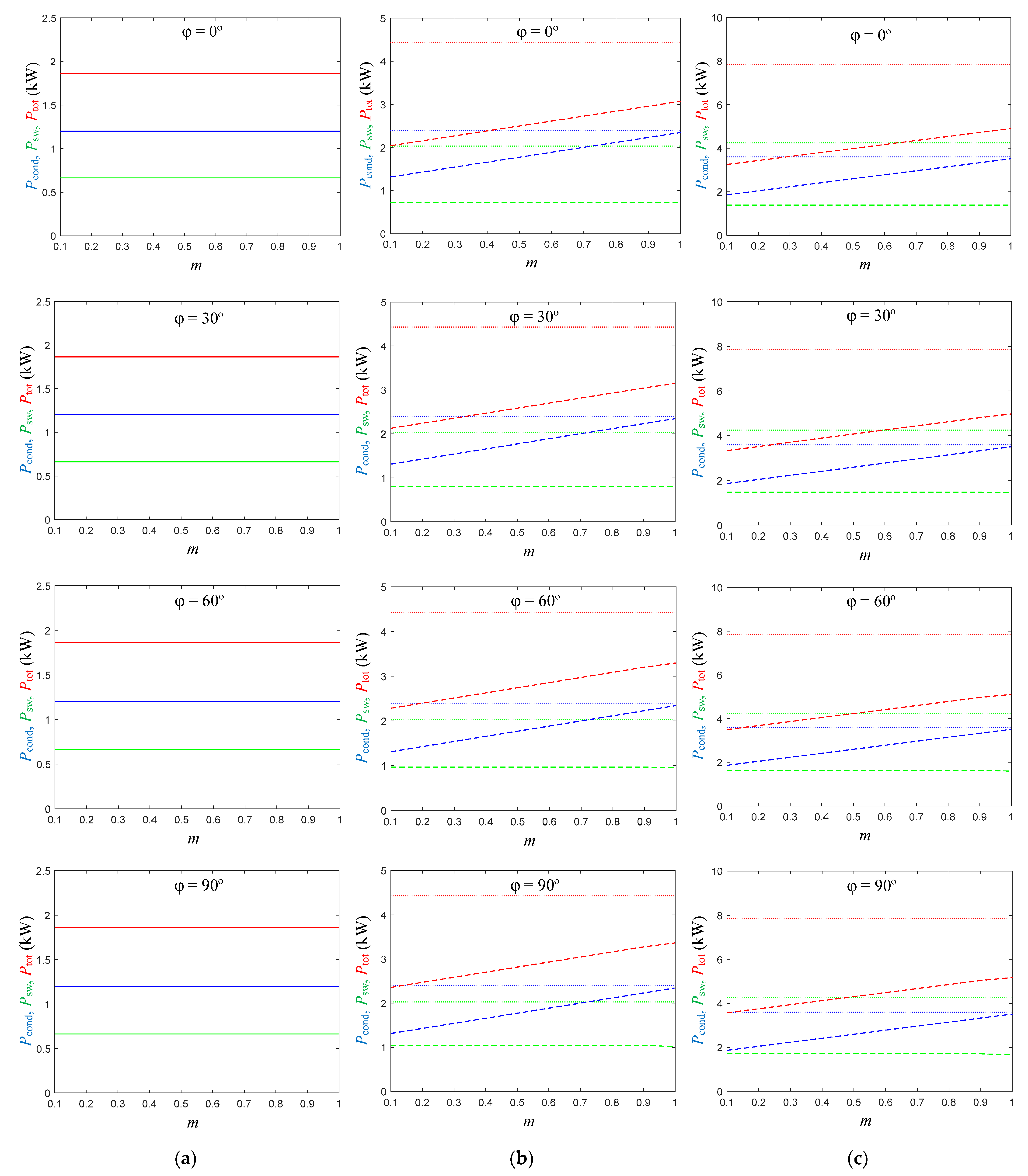
Figure 4 and
Figure 5 present the average (over the fundamental period) conduction (
Pcond), switching (
Psw), and total (
Ptot =
Pcond +
Psw) inverter power losses as a function of the modulation index
m for several motor phase current-voltage displacement angles
φ.
Figure 4 shows the results under the nominal phase current (
Iph,nom in
Table 1), and
Figure 5 shows the results under 0.25·
Iph,nom. It can be observed that the conduction and switching losses (blue and green waveforms) have the same order of magnitude, so that the total loss is similarly influenced by both types of losses. In the case of EV
1, designs A and B are the same and, therefore, present the same losses. Regarding EV
2 and EV
3, design B features lower total loss (red waveform) than design A. Therefore, design B is clearly superior from the inverter loss point of view.
It is worth highlighting that in design B, cases EV2 and EV3, the conduction loss diminishes as the modulation index m reduces. This occurs because as the modulation index decreases, in the multilevel converter legs, the duty ratio of connection to the inner dc-link points increases while the duty ratio of connection to the outer dc-link points decreases. Since the connection to the inner dc-link points presents redundant paths while the connection to the outer dc-link points presents just one path, this contributes to reducing the overall conduction losses.
3.4. Motor Ac-Voltage Harmonic Distortion
The harmonic distortion of the motor voltages is another important parameter to be evaluated. A lower line-to-line harmonic distortion implies lower harmonic losses in the motor and lower electromagnetic interference [
26,
27,
28,
29].
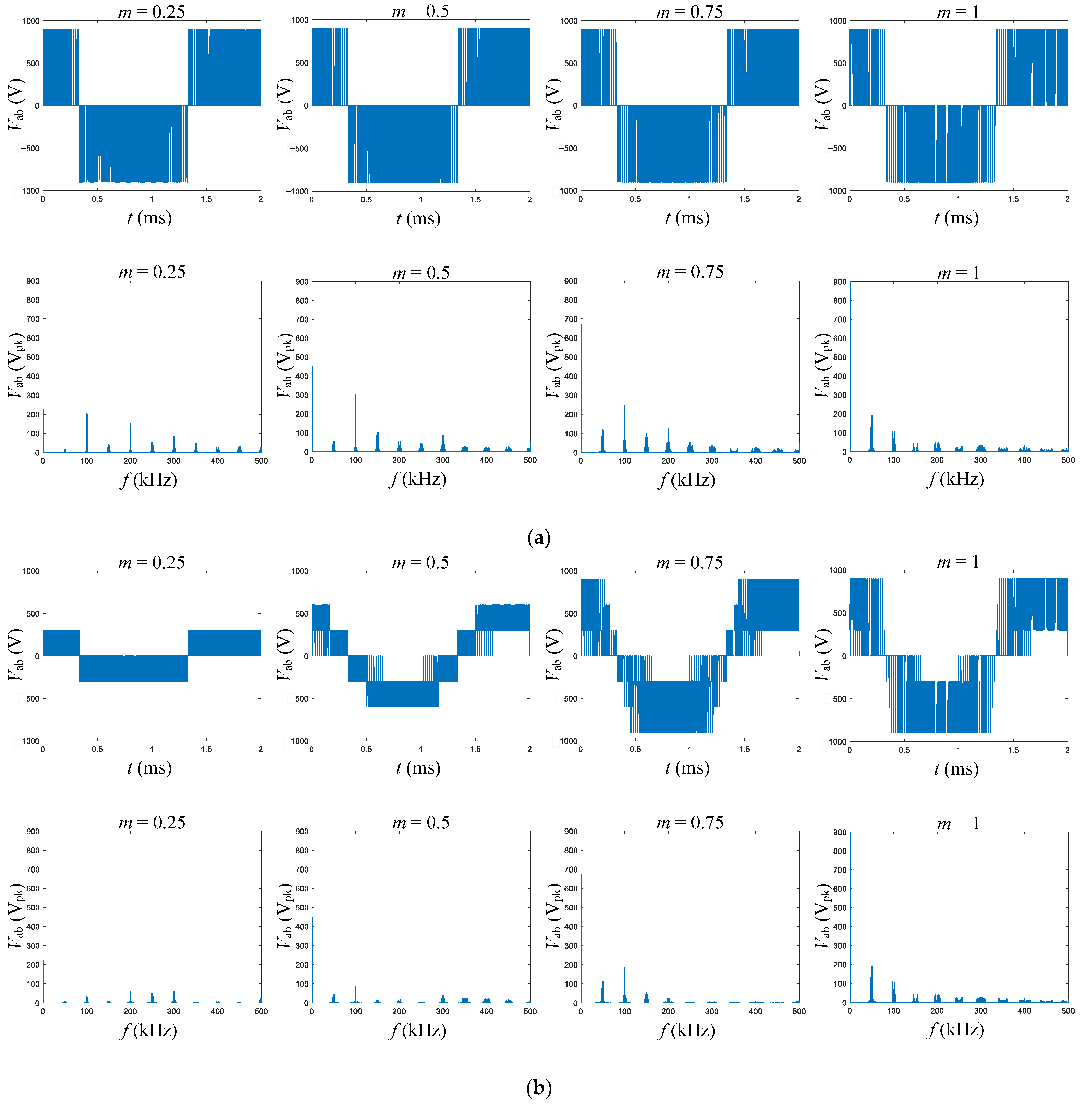
Figure 6 presents the time-domain and frequency-domain plots of the motor line-to-line voltage under four different modulation index values in the EV
1 case. In this case, design approaches A and B are the same, as they both use a conventional two-level inverter. It can be observed that, at low modulation index values, the most prominent harmonics appear around twice the switching frequency, while the harmonics around the switching frequency gain in significance as the modulation index increases.
Figure 7 and
Figure 8 show the same plots in the EV
2 and EV
3 cases, respectively. Here, design approach B allows a significant reduction of the harmonic distortion compared to design approach A, thanks to the increase in the number of available levels to synthesize the line-to-line voltage. The advantage is especially noticeable at low modulation index values and decreases as the modulation index increases.
Figure 9 plots the resulting total harmonic distortion (THD) values as a function of the modulation index for all three vehicles. The advantage in harmonic distortion of design approach B is clear.
3.5. Motor Common-Mode Voltage
In this subsection, the motor common-mode voltage is analyzed in both design approaches. The inverter operation generates a common-mode voltage at the inverter ac terminals, which represents an average voltage between the motor stator windings and ground. Due to non-negligible parasitic capacitances, the impedance between the stator windings and ground is finite, and then, the common-mode voltage causes the circulation of a common-mode current through this impedance that typically leads to undesirable effects. For instance, this common-mode current flows through the motor bearings, which causes bearing degradation and lifetime reduction, or it may cause electromagnetic interferences in other systems [
30,
31]. Consequently, a reduced common-mode voltage improves the system operation and extends the lifetime of the motor drive.
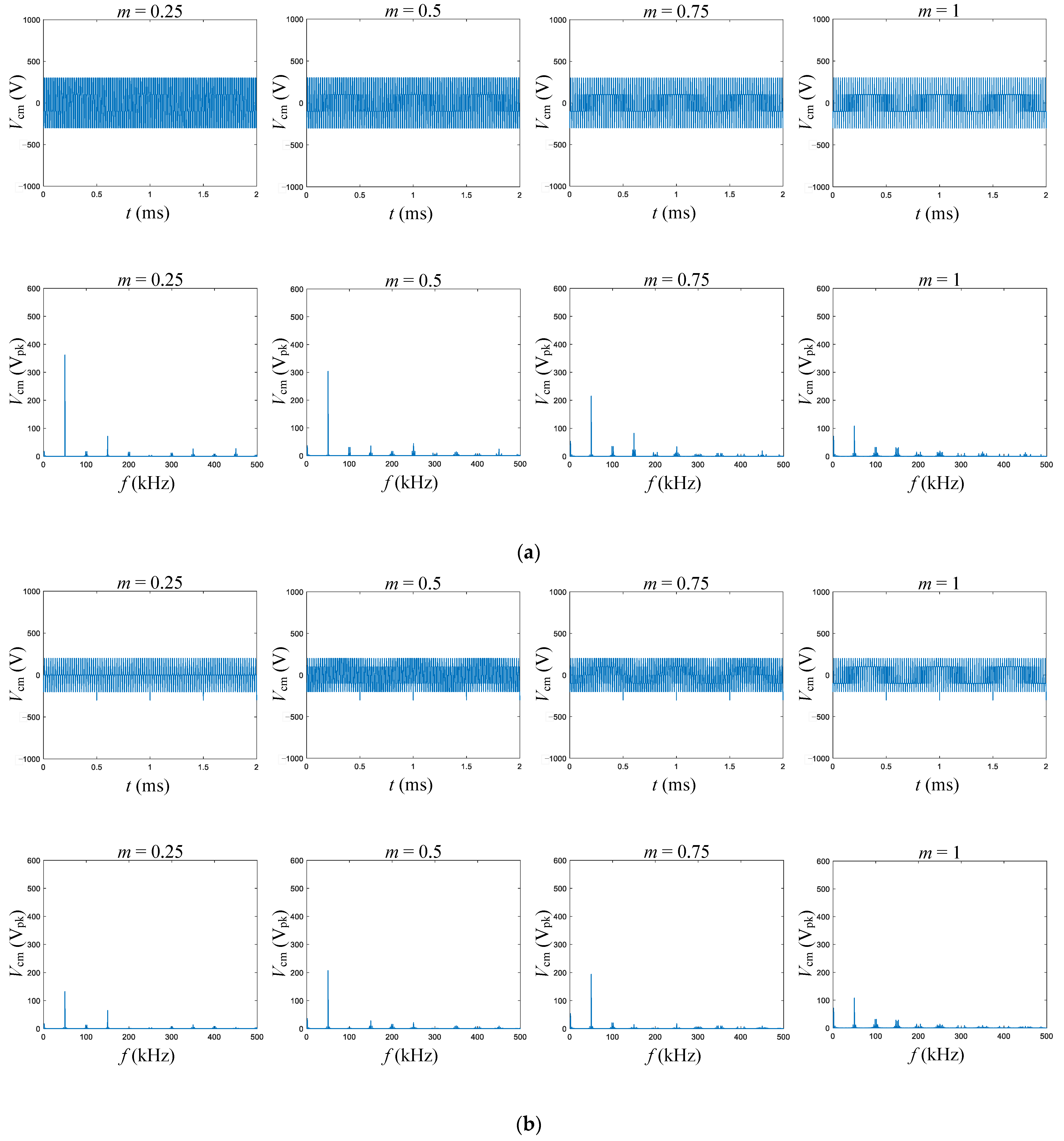
Figure 10 presents the time-domain and frequency-domain plots of the motor common-mode voltage under four different modulation index values in the EV
1 case. In this case, design approaches A and B are the same, as they both use a conventional two-level inverter. It is interesting to note that the amplitude of the most significant component of the common-mode voltage, at the switching frequency, decreases as the modulation index increases.
Figure 11 and
Figure 12 show the same plots in the EV
2 and EV
3 cases, respectively. Here, design approach B allows a significant reduction of the common-mode voltage compared to design approach A, thanks to the increase in the number of available levels to synthesize the motor voltage. The advantage is especially noticeable at low modulation index values and decreases as the modulation index increases.
Figure 13 plots the resulting rms value of the common-mode voltage as a function of the modulation index for all three vehicles. The advantage in common-mode voltage of design approach B is clear.
3.6. Inverter Mean Time to Failure
Another important traction inverter feature is its reliability [
3]. In this subsection, the inverter leg reliability in both design approaches is compared considering only the failure of the MOSFET power devices.
Table 2 indicates the normalized failure rates of the three MOSFETs, which are assumed to be proportional to the rated voltage to account for the higher complexity and lower design and manufacturing optimization of a less frequently used higher-voltage-rated device. For the sake of simplicity, the failure rate is assumed to be constant and independent of the current, temperature, and switching frequency of the device.
It is also assumed that the MOSFETs always fail in open-circuit. In case of short-circuit failure, it is assumed that a specific MOSFET design and/or an auxiliary circuitry [
19] guarantees the conversion of the short-circuit failure into an open-circuit failure.
The inverter leg MTTF values shown in
Table 5 were calculated with the method detailed in [
32], employing Markov models of two-level, three-level and four-level ANPC legs. These Markov models consider all possible partial failure states involving one or more failed power switches in the inverter leg. It is worth highlighting that ANPC legs, thanks to their intrinsic redundancies, can maintain operation in case of failure of one or more power switches. That is, a switch failure does not necessarily lead to a full converter shutdown.
The leg is assumed to reach the failure state when the leg ac terminal can only be connected to one or none dc-link points. Multilevel legs have a larger number of devices than a conventional two-level leg, and thus may experience MOSFET failures earlier than in a two-level leg for the same MOSFET failure rate. However, multilevel legs also feature more than two dc-link points and eventually more than one path of connection to these dc-link points. Therefore, the number of MOSFET failures necessary to reach the leg failure state increases compared to the two-level case, where a single MOSFET failure leads to a full leg shutdown.
Table 5 presents the normalized value of the MTTF of an inverter leg for each vehicle case and design approach. In design A, the MTTF decreases as the dc-bus voltage increases, while in design B, the MTTF remains approximately constant. Thus, according to this simplified analysis, design B features potentially higher reliability compared to design A.
3.7. Summary of the Simulation Results
This subsection summarizes the most relevant results of the simulations. Design B presents significantly better figures than design A, being clearly superior.
3.7.1. Modularity and Complexity
Modularity: Design B is superior to design A since it requires only one type of battery pack and MOSFET.
Complexity: Both designs show similar complexity, since design A requires a smaller number of components but higher diversity than design B.
3.7.2. Battery Pack SoC Balancing
In design B, the SoC balancing control can be integrated with the inverter. No external circuits or devices are required, and this control is achieved without additional losses. Instead, in design A, SoC balancing control relies on a BMS that causes additional losses. Thus, design B is clearly superior.
3.7.3. Inverter Loss
The inverter loss is smaller in design B than in design A, for any value of both the inverter current and the displacement angle. The inverter loss reduction of design B with reference to design A increases as the modulation index decreases, reaching values up to 55% reduction at the nominal current in the EV3 case.
3.7.4. Motor Ac-Voltage Harmonic Distortion
Design B provides lower motor ac-voltage total harmonic distortion than design A, particularly at low modulation index values, reaching up to 65% reduction in the EV3 case. For m = 1, both designs provide the same ac-voltage distortion.
3.7.5. Motor Common-Mode Voltage
Design B generates lower common-mode voltage than design A. Both designs show similar common-mode voltage at m = 1. As the modulation index decreases, the common-mode voltage of design B presents a higher percentage reduction relative to design A, reaching values of up to 75% reduction in EV2.
3.7.6. Inverter Mean Time to Failure
As the dc-bus voltage increases, the MTTF of design B remains approximately constant and significantly higher than that of design A. Therefore, design B features higher reliability than design A.
4. Conclusions
In this work, two different approaches were considered for the design of the traction inverter of three vehicles with different power and voltage ratings: design approach A, using a conventional two-level converter, and design approach B, using a multilevel NPC converter and a modular battery bank.
The two design approaches were compared according to several aspects. While design A features a slight advantage regarding inverter complexity, design B is clearly superior regarding modularity and battery pack SoC balancing. Under the selected design scenario, the comparison study shows that the proposed design approach provides a reduction of up to 55% in inverter losses, a reduction of up to 65% in motor ac-voltage total harmonic distortion, and a reduction of up to 75% in rms common-mode voltage.
However, design B has the drawback of requiring multiple units of the basic battery module and power switch to be efficiently and reliably assembled together. An efficient and reliable assembly method should be conceived in order to achieve a robust assembly consuming the lowest cost, time and space.
In addition, compared to a two-level inverter design approach where only two wires are needed to connect the battery to the inverter, in a multilevel NPC inverter, more than two wires are needed. Although the current rating of these additional wires is much smaller than the rating of the two basic outer wires, the distance between the battery system and the inverter should be reduced as much as possible to reduce the total wire length needed.
Finally, it is worth highlighting that the proposed design approach introduces additional complexity since multiple units of a basic battery module and multiple units of a power switch are required. However, this opens an opportunity for standardization of these two basic elements and offers novel degrees of freedom to improve the performance of the battery and the inverter. In the battery, part of the battery management system functions can be integrated with the inverter, e.g., providing a lossless battery SoC balancing of the battery modules. In the inverter, the use of multiple power switches presents the possibility of increasing the efficiency, improving the distribution of losses and increasing the power density, as well as improving the fault tolerance and reliability. Exploiting these opportunities is an interesting future research line.
Author Contributions
Conceptualization, S.B.-M.; introduction, S.A. and S.B.-M.; design scenario definition, S.B.-M., J.B. and G.G.-R.; simulations, S.B.-M.; analysis, S.B.-M. and S.A.; writing—original draft preparation, S.B.-M.; writing—review and editing, S.A., S.B.-M., J.B. and G.G.-R.; project administration, S.B.-M.; funding acquisition, S.B.-M. All authors have read and agreed to the published version of the manuscript.
Funding
This project has received funding from the European Union’s Horizon 2020 research and innovation programme under grant agreement No. 963646. The content of this manuscript only reflects the views of its authors. The European Commission and its agency are not responsible for any use that may be made of the information it contains.
![Electronics 12 00266 i001]()
Data Availability Statement
Acknowledgments
The authors would like to thank all of the members of the Helios consortium for the enriching discussions regarding this work, which have significantly impacted the design of the present study. In particular, we would like to thank Alber Filbà-Martínez and Lluís Trilla from the Catalonia Institute for Energy Research, Luis Romeral from Universitat Politècnica de Catalunya, Corneliu Barbu and Farshid Naseri from Aarhus University, Markus Schweizer-Berberich and Juan Alberto Romero from Vitesco Technologies GmbH, and Türev Sarikurt from TÜBITAK RUTE.
Conflicts of Interest
The authors declare no conflict of interest. The funders had no role in the design of the study; in the collection, analyses, or interpretation of data; in the writing of the manuscript, or in the decision to publish the results.
References
- Maroti, P.K.; Padmanaban, S.; Bhaskar, M.S.; Ramachandaramurthy, V.K.; Blaabjerg, F. The State-of-the-Art of Power Electronics Converters Configurations in Electric Vehicle Technologies. Power Electron. Devices Compon. 2022, 1, 100001. [Google Scholar] [CrossRef]
- Cantor, C.; Soulopoulos, N.; Fisher, R.; O’Donovan, A.; Cheung, A. Zero-Emission Vehicles Progress Dashboard; BloombergNEF: London, UK, 2022; Available online: https://zevtc.org/wp-content/uploads/2022/09/ZEV-Dashboard-_September-for-publication.pdf (accessed on 11 October 2022).
- Reimers, J.; Dorn-Gomba, L.; Mak, C.; Emadi, A. Automotive Traction Inverters: Current Status and Future Trends. IEEE Trans. Veh. Technol. 2019, 68, 3337–3350. [Google Scholar] [CrossRef]
- Poorfakhraei, A.; Narimani, M.; Emadi, A. A Review of Modulation and Control Techniques for Multilevel Inverters in Traction Applications. IEEE Access 2021, 9, 24187–24204. [Google Scholar] [CrossRef]
- Becker, J.; Nemeth, T.; Wegmann, R.; Sauer, D.U. Dimensioning and Optimization of Hybrid Li-Ion Battery Systems for EVs. World Electr. Veh. J. 2018, 9, 19. [Google Scholar] [CrossRef] [Green Version]
- Naseri, F.; Barbu, C.; Sarikurt, T. Optimal Sizing of Hybrid High-Energy/High-Power Battery Energy Storage Systems to Improve Battery Cycle Life and Charging Power in Electric Vehicle Applications. J. Energy Storage 2022, 55, 105768. [Google Scholar] [CrossRef]
- Busquets-Monge, S. Neutral-Point-Clamped DC-AC Power Converters. In Wiley Encyclopedia of Electrical and Electronics Engineering; John Wiley & Sons, Inc.: Hoboken, NJ, USA, 2018; pp. 1–20. [Google Scholar]
- Leon, J.I.; Vazquez, S.; Franquelo, L.G. Multilevel Converters: Control and Modulation Techniques for Their Operation and Industrial Applications. Proc. IEEE 2017, 105, 2066–2081. [Google Scholar] [CrossRef]
- Akagi, H. Multilevel Converters: Fundamental Circuits and Systems. Proc. IEEE 2017, 105, 2048–2065. [Google Scholar] [CrossRef]
- Alepuz, S.; Busquets-Monge, S.; Nicolás-Apruzzese, J.; Filbà-Martínez, À.; Bordonau, J.; Yuan, X.; Kouro, S. A Survey on Capacitor Voltage Control in Neutral-Point-Clamped Multilevel Converters. Electronics 2022, 11, 527. [Google Scholar] [CrossRef]
- Busquets-Monge, S.; Filba-Martinez, A.; Alepuz, S.; Nicolas-Apruzzese, J.; Luque, A.; Conesa-Roca, A.; Bordonau, J. Multibattery-Fed Neutral-Point-Clamped DC-AC Converter with SoC Balancing Control to Maximize Capacity Utilization. IEEE Trans. Ind. Electron. 2020, 67, 16–27. [Google Scholar] [CrossRef]
- Helios EU H2020 Project. European Union’s Horizon 2020 Research and Innovation Programme. Available online: https://www.helios-h2020project.eu/ (accessed on 11 October 2022).
- She, X.; Huang, A.Q.; Lucia, O.; Ozpineci, B. Review of Silicon Carbide Power Devices and Their Applications. IEEE Trans. Ind. Electron. 2017, 64, 8193–8205. [Google Scholar] [CrossRef]
- van der Broeck, H.W.; Skudelny, H.-C.; Stanke, G.V. Analysis and Realization of a Pulsewidth Modulator Based on Voltage Space Vectors. IEEE Trans. Ind. Appl. 1988, 24, 142–150. [Google Scholar] [CrossRef]
- Infineon Silicon Carbide CoolSiC MOSFETs. Available online: https://www.infineon.com/cms/en/product/power/mosfet/silicon-carbide/ (accessed on 11 October 2022).
- Rohm Semiconductor Silicon-Carbide (SiC) Power Devices. Available online: https://www.rohm.com/products/sic-power-devices (accessed on 11 October 2022).
- Busquets-Monge, S. A Simple Virtual-Vector-Based PWM Formulation for Multilevel Three-Phase Neutral-Point-Clamped DC–AC Converters Including the Overmodulation Region. Electronics 2022, 11, 641. [Google Scholar] [CrossRef]
- Wu, X.; Tan, G.; Ye, Z.; Yao, G.; Liu, Z.; Liu, G. Virtual-Space-Vector PWM for a Three-Level Neutral-Point-Clamped Inverter with Unbalanced DC-Links. IEEE Trans. Power Electron. 2018, 33, 2630–2642. [Google Scholar] [CrossRef]
- Filba-Martinez, A.; Busquets-Monge, S.; Alepuz, S.; Garcia-Rojas, G.; Luque, A.; Bordonau, J. An Intelligent Electronic Fuse for Selective Isolation of Faulty Switching Cells in Power Electronic Converter Legs to Guarantee Continuous Operation. IEEE J. Emerg. Sel. Top. Power Electron. 2022, 10, 7665–7676. [Google Scholar] [CrossRef]
- Zhang, D.-H.; Zhu, G.-R.; He, S.-J.; Qiu, S.; Ma, Y.; Wu, Q.-M.; Chen, W. Balancing Control Strategy for Li-Ion Batteries String Based on Dynamic Balanced Point. Energies 2015, 8, 1830–1847. [Google Scholar] [CrossRef] [Green Version]
- Gallardo-Lozano, J.; Romero-Cadaval, E.; Milanes-Montero, M.I.; Guerrero-Martinez, M.A. Battery Equalization Active Methods. J. Power Sources 2014, 246, 934–949. [Google Scholar] [CrossRef]
- Alvarez-Diazcomas, A.; Estévez-Bén, A.A.; Rodríguez-Reséndiz, J.; Martínez-Prado, M.A.; Carrillo-Serrano, R.V.; Thenozhi, S. A Review of Battery Equalizer Circuits for Electric Vehicle Applications. Energies 2020, 13, 5688. [Google Scholar] [CrossRef]
- Huang, W.; Abu Qahouq, J.A. Energy Sharing Control Scheme for State-of-Charge Balancing of Distributed Battery Energy Storage System. IEEE Trans. Ind. Electron. 2015, 62, 2764–2776. [Google Scholar] [CrossRef]
- Lu, L.; Han, X.; Li, J.; Hua, J.; Ouyang, M. A Review on the Key Issues for Lithium-Ion Battery Management in Electric Vehicles. J. Power Sources 2013, 226, 272–288. [Google Scholar] [CrossRef]
- Hoque, M.M.; Hannan, M.A.; Mohamed, A.; Ayob, A. Battery Charge Equalization Controller in Electric Vehicle Applications: A Review. Renew. Sustain. Energy Rev. 2017, 75, 1363–1385. [Google Scholar] [CrossRef]
- Bonnett, A.H. Analysis of the Impact of Pulse-Width Modulated Inverter Voltage Waveforms on AC Induction Motors. IEEE Trans. Ind. Appl. 1996, 32, 386–392. [Google Scholar] [CrossRef]
- Guillermo, R.A.; Valenzuela, M.A.; Weaver, M.D.; Lorenz, R.D. The Impact of Switching Frequency on PWM AC Drive Efficiency. In Proceedings of the IEEE Pulp, Paper & Forest Industries Conference (PPFIC), Austin, TX, USA, 19–23 July 2016; Volume 1, pp. 153–163. [Google Scholar]
- Papazacharopoulos, Z.C.; Kladas, A.G.; Manias, S.N. Investigation of the Switching Frequency Harmonics Impact on PWM Induction Motor Drive Efficiency. In Proceedings of the IEEE Power Electronics Specialists Conference (PESC), Vancouver, BC, Canada, 17–21 June 2001; Volume 2, pp. 1203–1208. [Google Scholar]
- Yang, J.J.; Nguyen, H.T.; Choi, S.S.; Zuhdi, M. Maximizing Motor Load Lifetime through the Control of Harmonic Distortion Level. In Proceedings of the IEEE International Conference on Power System Technology (POWERCON), Zhejiang, China, 24–28 October 2010; pp. 1–6. [Google Scholar]
- Erdman, J.M.; Kerkman, R.J.; Schlegel, D.W.; Skibinski, G.L. Effect of PWM Inverters on Ac Motor Bearing Currents and Shaft Voltages. IEEE Trans. Ind. Appl. 1996, 32, 250–259. [Google Scholar] [CrossRef]
- Turzyński, M.; Musznicki, P. A Review of Reduction Methods of Impact of Common-Mode Voltage on Electric Drives. Energies 2021, 14, 4003. [Google Scholar] [CrossRef]
- Busquets-Monge, S.; Rafiezadeh, R.; Alepuz, S.; Filba-Martinez, A.; Nicolas-Apruzzese, J. Fast Reliability Assessment of Neutral-Point-Clamped Topologies through Markov Models. IEEE Trans. Power Electron. 2021, 36, 13449–13459. [Google Scholar] [CrossRef]
Figure 1.
Design A. (a) EV1. (b) EV2. (c) EV3 (for the sake of simplicity, the diodes in antiparallel with the MOSFETs have been intentionally omitted).
Figure 1.
Design A. (a) EV1. (b) EV2. (c) EV3 (for the sake of simplicity, the diodes in antiparallel with the MOSFETs have been intentionally omitted).
Figure 2.
Design B. (a) EV1. (b) EV2. (c) EV3 (for the sake of simplicity, the diodes in antiparallel with the MOSFETs have been intentionally omitted).
Figure 2.
Design B. (a) EV1. (b) EV2. (c) EV3 (for the sake of simplicity, the diodes in antiparallel with the MOSFETs have been intentionally omitted).
Figure 3.
Assumed MOSFET voltage vs (blue) and current is (red) waveforms in the switching transitions of power devices concentrating the switching losses.
Figure 3.
Assumed MOSFET voltage vs (blue) and current is (red) waveforms in the switching transitions of power devices concentrating the switching losses.
Figure 4.
Average conduction Pcond (blue), switching Psw (green), and total Ptot (red) inverter power loss at the nominal phase current (Iph,nom) and several motor phase current-voltage displacement angles φ, as a function of the modulation index. Dotted lines correspond to design A, dashed lines correspond to design B, and solid lines correspond to both design A and design B. (a) EV1. (b) EV2. (c) EV3.
Figure 5.
Average conduction Pcond (blue), switching Psw (green), and total Ptot (red) inverter power loss at one fourth of the nominal phase current and several motor phase current-voltage displacement angles φ, as a function of the modulation index. Dotted lines correspond to design A, dashed lines correspond to design B, and solid lines correspond to both designs A and B. (a) EV1. (b) EV2. (c) EV3.
Figure 6.
Time-domain and frequency-domain plots of the motor line-to-line voltage in EV1 under four different modulation index values. Designs A and B.
Figure 6.
Time-domain and frequency-domain plots of the motor line-to-line voltage in EV1 under four different modulation index values. Designs A and B.
Figure 7.
Time-domain and frequency-domain plots of the motor line-to-line voltage in EV2 under four different modulation index values. (a) Design A. (b) Design B.
Figure 7.
Time-domain and frequency-domain plots of the motor line-to-line voltage in EV2 under four different modulation index values. (a) Design A. (b) Design B.
Figure 8.
Time-domain and frequency-domain plots of the motor line-to-line voltage in EV3 under four different modulation index values. (a) Design A. (b) Design B.
Figure 8.
Time-domain and frequency-domain plots of the motor line-to-line voltage in EV3 under four different modulation index values. (a) Design A. (b) Design B.
Figure 9.
Total harmonic distortion of the line-to-line voltage as a function of the modulation index. Dotted lines correspond to design A, dashed lines correspond to design B, and solid lines correspond to both design A and design B. (a) EV1. (b) EV2. (c) EV3.
Figure 9.
Total harmonic distortion of the line-to-line voltage as a function of the modulation index. Dotted lines correspond to design A, dashed lines correspond to design B, and solid lines correspond to both design A and design B. (a) EV1. (b) EV2. (c) EV3.
Figure 10.
Time-domain and frequency-domain plots of the common-mode voltage in EV1 under different modulation index values. Designs A and B.
Figure 10.
Time-domain and frequency-domain plots of the common-mode voltage in EV1 under different modulation index values. Designs A and B.
Figure 11.
Time-domain and frequency-domain plots of the common-mode voltage in EV2 under different modulation index values. (a) Design A. (b) Design B.
Figure 11.
Time-domain and frequency-domain plots of the common-mode voltage in EV2 under different modulation index values. (a) Design A. (b) Design B.
Figure 12.
Time-domain and frequency-domain plots of the common-mode voltage in EV3 under different modulation index values. (a) Design A. (b) Design B.
Figure 12.
Time-domain and frequency-domain plots of the common-mode voltage in EV3 under different modulation index values. (a) Design A. (b) Design B.
Figure 13.
Root-mean-square value of the common-mode voltage as a function of the modulation index. Dotted lines correspond to design A, dashed lines correspond to design B, and solid lines correspond to both design A and design B. (a) EV1. (b) EV2. (c) EV3.
Figure 13.
Root-mean-square value of the common-mode voltage as a function of the modulation index. Dotted lines correspond to design A, dashed lines correspond to design B, and solid lines correspond to both design A and design B. (a) EV1. (b) EV2. (c) EV3.
Table 1.
Vehicle design specifications.
Table 1.
Vehicle design specifications.
| Parameters | Vehicle 1 (EV1) | Vehicle 2 (EV2) | Vehicle 3 (EV3) |
|---|
| Pnom [kW] | 50 | 100 | 150 |
| VB [V] | 300 | 600 | 900 |
| mnom | 0.75 | 0.75 | 0.75 |
| φnom [degrees] | 30 | 30 | 30 |
| Iph,nom [Arms] | 200 | 200 | 200 |
| fo [Hz] | 500 | 500 | 500 |
Table 3.
Modularity evaluation. Component count to produce a set of three units (one unit of EV1 plus one unit of EV2 plus one unit of EV3).
Table 3.
Modularity evaluation. Component count to produce a set of three units (one unit of EV1 plus one unit of EV2 plus one unit of EV3).
| | | Number of Components |
|---|
| Component Category | Component Type | Design A | Design B |
|---|
| Battery pack | 300 V | 1 | 6 |
| 600 V | 1 | 0 |
| 900 V | 1 | 0 |
| MOSFETs | M1 | 6 | 60 |
| M2 | 6 | 0 |
| M3 | 6 | 0 |
Table 4.
Complexity evaluation.
Table 4.
Complexity evaluation.
| Parameters | Design A | Design B |
|---|
| Number of battery pack types (Bt) | 3 | 1 |
| Number of battery packs (Bn) | 3 | 6 |
| Number of MOSFET types (Mt) | 3 | 1 |
| Number of MOSFEts (Mn) | 18 | 60 |
| Battery bank complexity (BBC = Bt·Bn) | 9 | 6 |
| Inverter complexity (IC = Mt·Mn) | 54 | 60 |
Table 5.
Inverter leg MTTF evaluation.
Table 5.
Inverter leg MTTF evaluation.
| Case | MTTF [p.u.] |
|---|
| Design A | Design B |
|---|
| EV1 | 0.50 | 0.50 |
| EV2 | 0.25 | 0.55 |
| EV3 | 0.17 | 0.56 |
| Disclaimer/Publisher’s Note: The statements, opinions and data contained in all publications are solely those of the individual author(s) and contributor(s) and not of MDPI and/or the editor(s). MDPI and/or the editor(s) disclaim responsibility for any injury to people or property resulting from any ideas, methods, instructions or products referred to in the content. |
© 2023 by the authors. Licensee MDPI, Basel, Switzerland. This article is an open access article distributed under the terms and conditions of the Creative Commons Attribution (CC BY) license (https://creativecommons.org/licenses/by/4.0/).


