1. Introduction
Composite materials and structures are now being exploited in a wide range of applications from the automotive to the medical industry [
1,
2,
3]. There are some important advantages, such as high strength, excellent fatigue properties, and low weight. Additionally, they do not corrode, can tailor laminate to loads, and can enable very significant part count reduction.
Composite materials are manufactured from at least two components—fiber and resin. Advanced composite materials, widely used for the aerospace industry, have a specific structure and reinforcement that can be made out of carbon fiber [
4], fiberglass [
5], or Kevlar [
6].
The fibers can be made of different materials, but the most used is carbon fiber. Fibers are bundled together to make yarns. The production of carbon fiber, in the latest years, increases significantly [
7], enabling the development of the industry.
Typically, there are two types of carbon fiber: pre-impregnated fiber, meaning an additional process is not needed during its manipulation, or dry fiber, for when it is necessary to consider a resin bath during the manipulation.
There are some steps to be followed to obtain the pre-impregnated carbon fiber. The carbon fiber is unrolled from the tow and placed in a resin bath, directed by a rolls system. From the resin bath, it is placed in a high-speed oven to dry back and then rolled to a tow. The impregnation of the fiber during the manipulation is realized in a similar way, except that the oven is missing in this step, but it is placed after the complete part is ready.
The winding process is a general procedure, used in several areas. The winding process can be done differently depending on the product and technological evolution. According to [
8], compared to conventional winding techniques, cable winding includes fewer manufacturing steps and is therefore likely to be better suited for automated production. Automation of the cable winding production step is a crucial task to lower the manufacturing costs of these machines.
A robot cell offline simulation was posed in [
8] and used during the development of a functional automated cable winding production cell to validate its function. It is presented as a robotic cell with ABB Robots used for copper fiber winding around the stator. The process contains a feeding component [
9] to control the fiber quantity, but also to keep the fiber tension constant. In the actual study, in testing the concept phase a Robot Studio simulation was also created, where all the components from the system are placed. Another strategy is to use MATLAB to simulate the trajectory of the robot [
10]. In ref. [
10], some simulation tests were presented, which are also performed in the actual research, concerning:
MATLAB (R2018b) software is used because the winding die is a cylinder shape, and the mathematical model was available to be calculated. In the actual study, the identification of the mathematical model is complicated to identify because:
The advantages of winding automatization can be observed in [
8]. For the presented process, the costs were reduced from 1.8 to 0.2 million euro. However, the costs are not the only important benefits. Better control of the system is also important, meaning higher quality and accuracy. For this, in [
11] some characteristics were studied in more detail, such as fiber tensioning or friction with the deposition head.
In ref. [
12], the authors analyze the automatization opportunity of the winding process using carbon fiber processed by a robotic system. It was assumed that the tape tension is as constant as possible, and the deposition head and the robot arms should move on collision-free trajectories. The system also included components such as a feeding device made out of the main frame, a roving guide system, a roving tensioner, and a deposition system. It is important to mention that all of these components are placed, taking into consideration the carbon fiber flow, before the deposition head and before the winding die. The study proves that there is an influence of speed, more visible in the curves. From the beginning, the author considered the fiber tension constant. This is not difficult to obtain for a simple winding process [
12], but for a complex die, where also a robot with a complex trajectory is involved, it is impossible to do it without a complex tensioning device. In the robotic winding processes as in the patent [
13], the carbon fiber place must be considered. In [
12], it is placed directly on the robot arm, next to the deposition head. This solution does not consider dry carbon fibers. Moreover, it is not considering the necessary space and also to change the fiber tow it is necessary to stop the process, meaning that the human has to interact with the robot. In addition, one of the missing aspects of this solution is the tensioning option, but the method of implementing the trajectory, by using the virtual model of the winding die from where the nominal trajectory of the robot is generated. Parallel to this, in [
14] a specialized software made in MATLAB is proposed to generate the trajectory for a single robot system. In ref. [
15], winding using a single robot is proposed, using a tensioning device but a standard model. In an extension, the work can be considered as using a multi-robot winding system, because it proposed a mobile winding die for a simple trajectory.
According to [
15] the programming effort of teaching robots winding is currently high due to missing commercial path generation software, standard ones, not generated using the CAD drawing line, as in [
13]. The effort for teaching two cooperative robots is significantly higher than for one single robot. Collaborative robots tend to be used in more sensitive areas, such as medicine, where using other robot assistant systems, such as force control, can be used with a high accuracy [
16]. The disadvantages of these systems are the speed and the environmental conditions.
The necessity of using multiple robot cells comes from the complexity of the winding die. There are three categories of winding die:
For the first type, a single robot or actuator system is enough to proceed with the winding. For the second category, in most cases, a robot and a mobile winding die are used to complete the robot’s reachability points [
15]. For the last option with multiple-axis winding dies [
17], it is recommended to use a multiple-robot system. The advantages are related to the flexibility of the system, speed, and accuracy. In this study, it is also considered a multi-axis winding die with a multi-robot system.
For the manufacturing of new materials made with carbon fiber, there are several modeling methods [
18]. For the moment, the modeling methods are not in a high process of automatization, even the composite materials are a necessity of every major company in the mentioned industries. The reasons for this lack are connected to the high price of carbon fiber and its modeling methods [
19]. These methods are not yet very stable and suitable for automatization.
In this study, a solution for the modeling method of carbon fiber is proposed. Furthermore, the purpose of the study is to identify automatization methods for carbon fiber modeling that are fast, low cost, and more efficient. We also want to obtain an increased quality of the resulting composite materials. Two of the most important modeling methods of carbon fiber are considered: the placement method and especially the winding method. From the previous studies [
20,
21,
22,
23,
24,
25], it was observed that in the winding process the most important parameters are the trajectory, speeds, and especially tension of the fiber during the process.
The main objective of this research is to obtain a complete system, hardware and software, which can build composite materials using the winding process taking into consideration the most important composite structure characteristics. For the automatization of the winding process, we considered other continuously developing areas for automatization, respectively, the robotization of the processes.
The research proposed an integrated winding system for carbon fiber using two industrial robots and tensioning systems in order to obtain a fast process for finite composite parts. Thus, we propose a new production method for composite materials made from carbon fiber using the winding process with a high potential on both a high volume of parts and unique objects production.
3. Simulations and Study Results
3.1. Mathematical Model
Three tests were conducted in the experiments. The first one uses the formula with a reference of the motor having at 0 rotations, the reference force 500 [N/100], (
Figure 12—blue line). The second test was made with the reference force modified to 1000 [N/100], (
Figure 12—red line). During the tests, it was observed that the used spring is not strong enough to press on the fiber with the necessary force to be stronger in a normal state than the one coming from the fiber role perturbation. The last tests, (
Figure 12—grey line) were conducted with a changed spring, stronger, but keeping the modified reference. From this, the high force is also coming at the beginning. It is combining perturbation, from the source role, with the tensioning force. To have a bigger amplifier, the reference was increased to 1200 [N/100], which is closer to the source role average force to be applied in the position, and also an amplifier factor was added.
After the formula was changed, some improvements can be seen, but in some points, we can still see a big drop in the tension, which will influence the properties of the final product.
An additional amplifier was added in order to make the relation between force and position more stable for the experimental tests:
Even if the amplifier value was changed, it can still be seen drop of the tension, and even worst high fluctuation on the force value.
In the previous test, the weight of the tensioning device was not considered, and it was observed that it has an influence, therefore the tension from the fiber was released and new offsets in the force measuring device were set. The tool weight was compensated very well, but we still can see a drop from 1500 to 1100 [N/100] (
Figure 13), which is not so big considering the initial version of the system. However, it is not providing a very good solution for the moment.
The automatic fiber tensioning system is partially functional only by using an amplifier in the force position conversion.
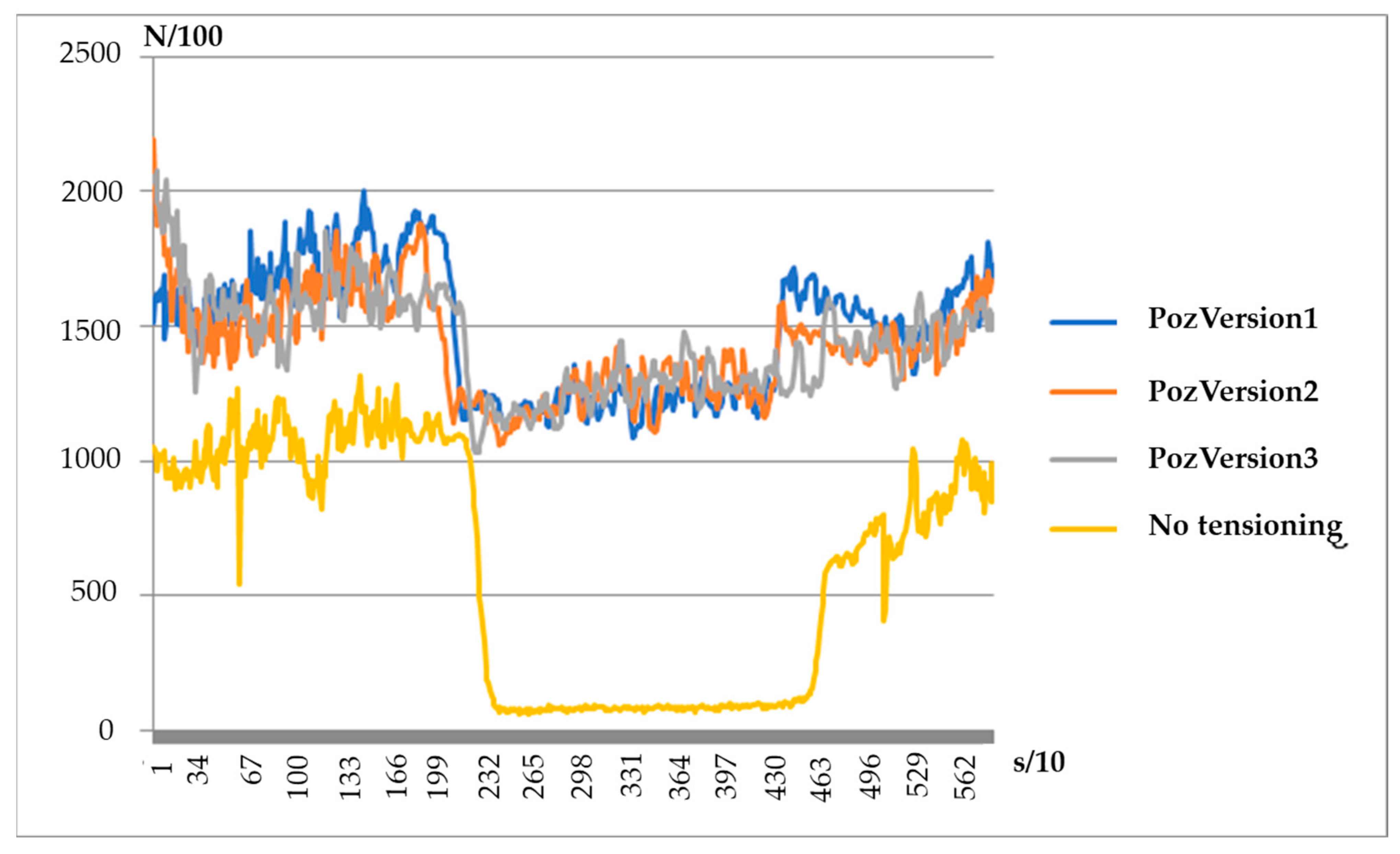
The next step was to apply a close loop controller with a regulator similar to P or PI to observe the influence on the fiber tensioning. All these tests were applied to a simple matrix. The next steps will be to apply the tensioning device together with a robotic collaborative system with high complexity matrix. The reference tension is set to 1400 [N/100].
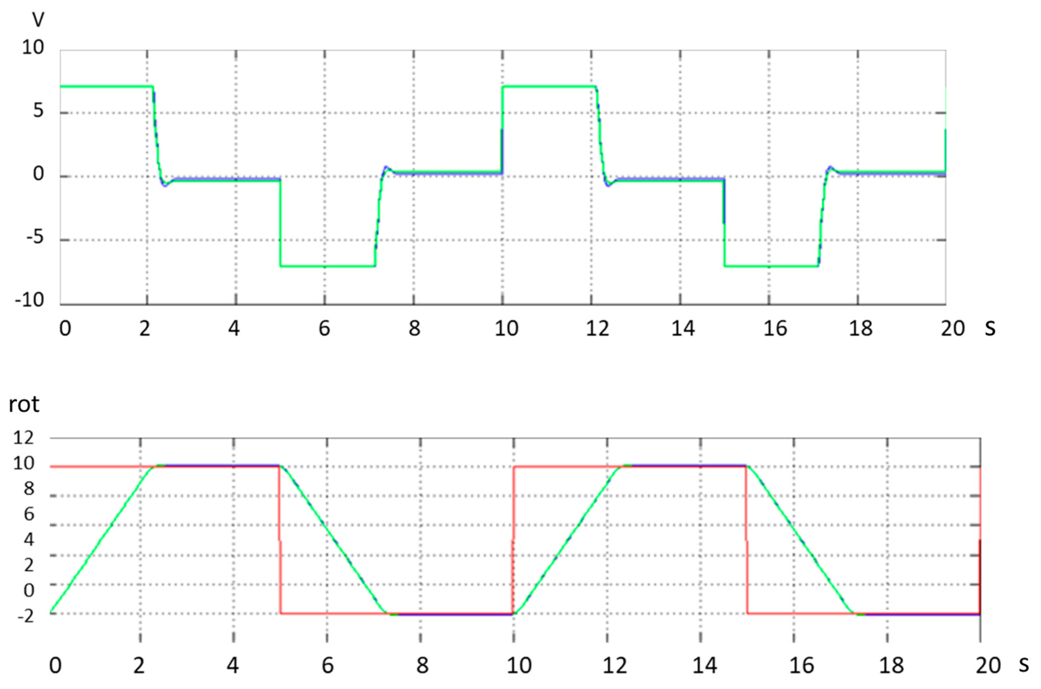
The position formula is made of:
For Version 1 (PozPV1) we test with the following default values:
MaxRotation = 10.
MaxError = 2000.
ReferenceForce = 1400.
For Version 2 (PozPV2) we test with the following default values:
MaxRotation = 15.
MaxError = 2000.
For Version 3 (PozPV3) we test with the following default values:
MaxRotation = 20.
MaxError = 2000.
For Version 4 (PozPV4) we test with the following default values:
MaxRotation = 10.
MaxError = 1300.
For Version 5 (PozPV5) we test with the following default values:
MaxRotation = 15.
MaxError = 1300.
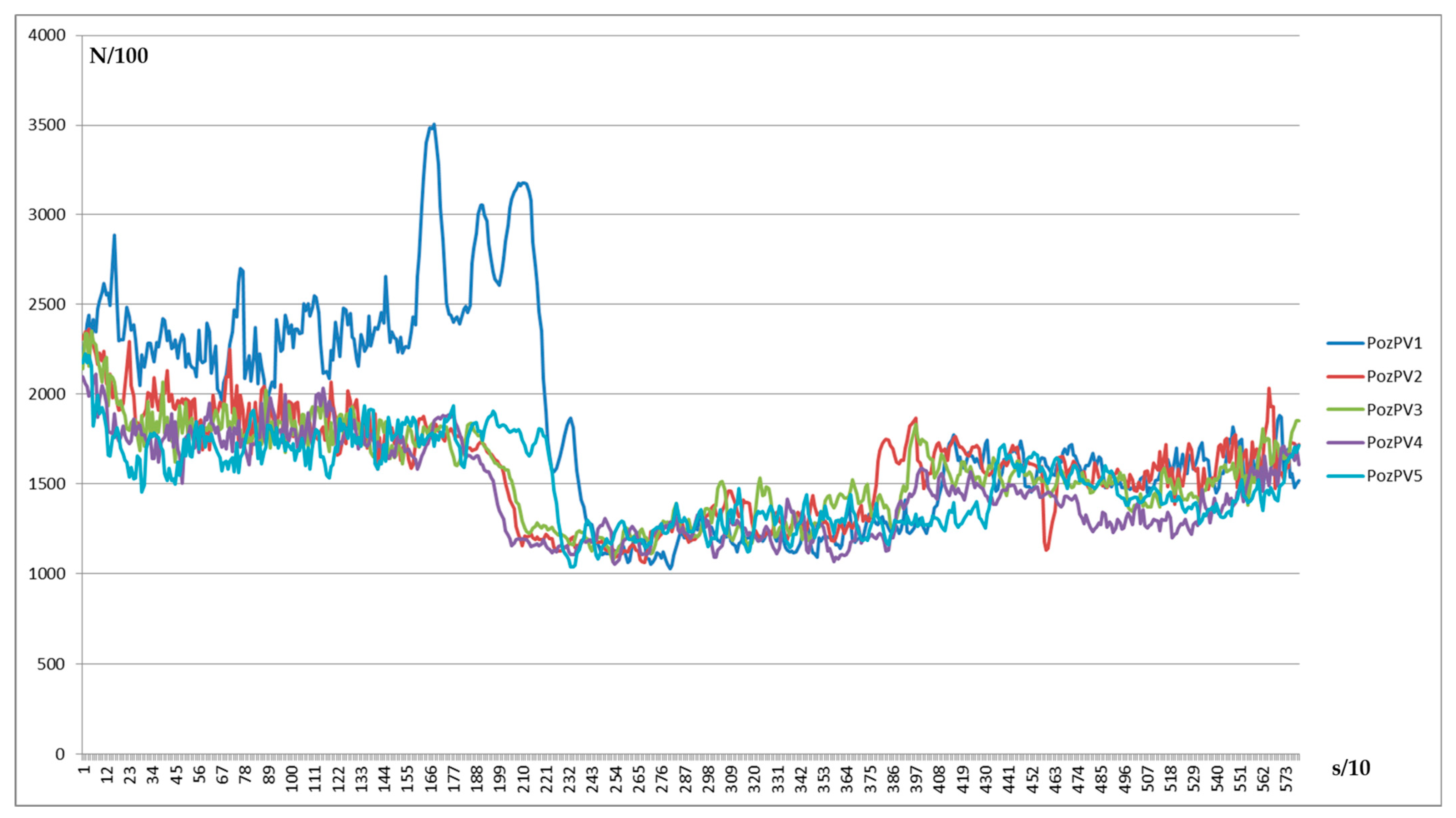
The tests from
Figure 14, with the proportional regulator, show that version 3 of the parameters brings the best compensation force results.
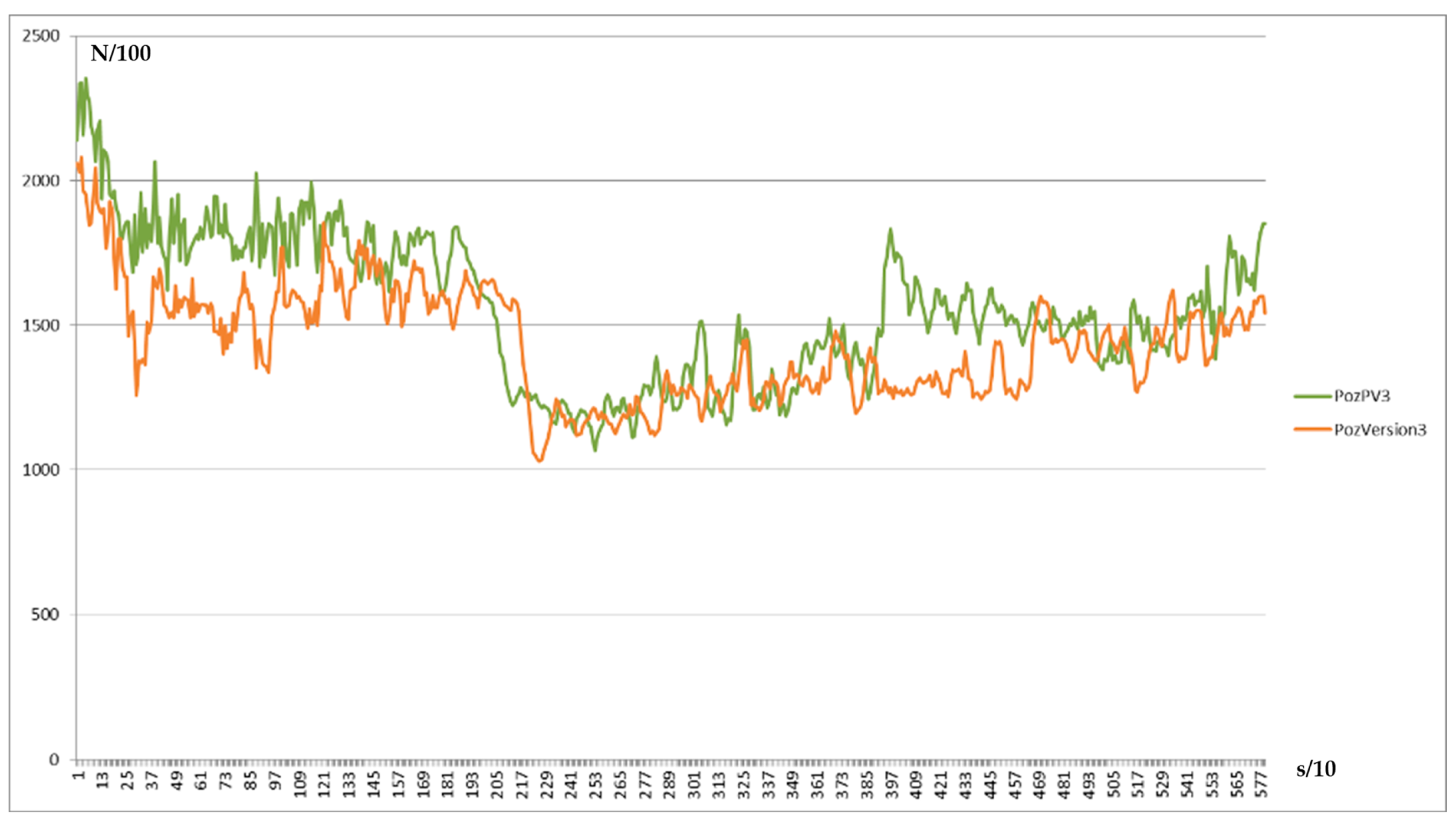
Even with a Proportional control, the improvements are visible (
Figure 15), but not so big, so this Proportional Regulation is only the first step.
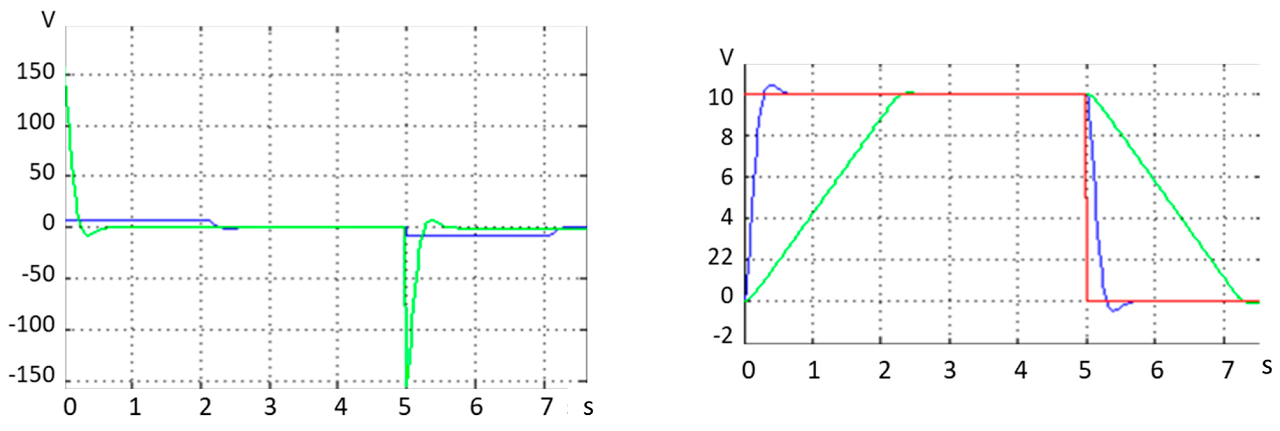
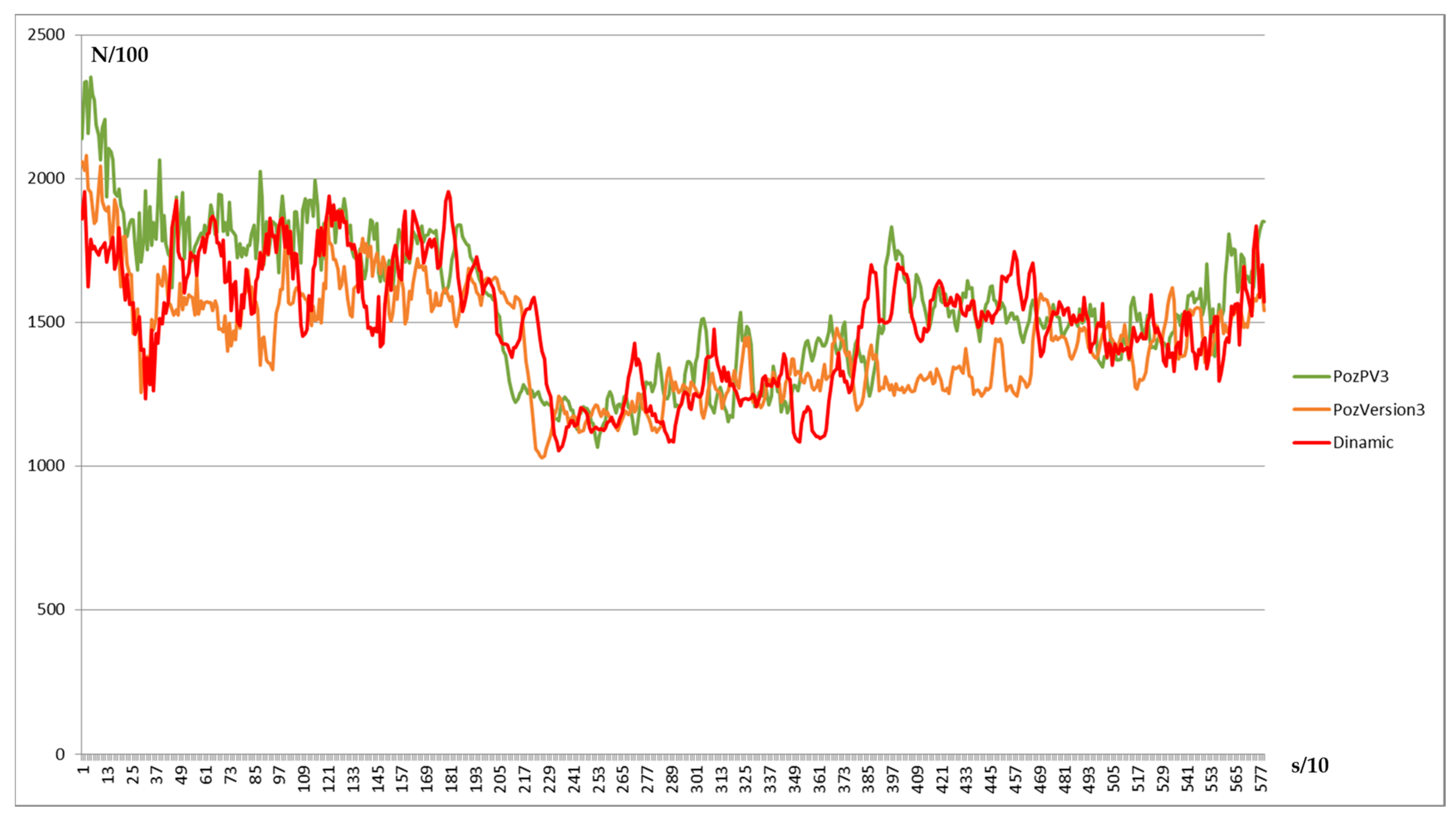
A dynamical formula coming from a bipolar combined with the Proportional control method was also tested, like:
With a bipolar version of the controller, big influences between some limits appear (
Figure 16). On average, the control is better but it is not possible to consider this option because of the big fluctuations.
The last version of Proportional control shows a smaller drop but is not settling the force value on the reference, which can be observed, in the first period it is approximately 1600 (N/10). The last version of PI is stabilized at the value of 1400 but it has a bigger drop.
If we make an average of all the measured values, the result is 1402. Very close to the reference.
The problem now is the big oscillations and especially the drop at the middle of the trajectory. This is the area where the direction of the deposition head is changed from a direction opposite to the roll to a direction in the same way as the fiber source roll.
The necessary time for the motor to compensate for the change is approximately 2 s, resulting from the motor control system.
3.2. Control System Proposal
Considering the results from the Proportional control, the better solution is to add an Integrator to make the settling faster. Therefore, to implement a PI control with the following general consideration:
MaxRotation = 15;
MaxError = 2000;
a1 = −1;
SamplingPeriod = 0.073;
Ti = 10;
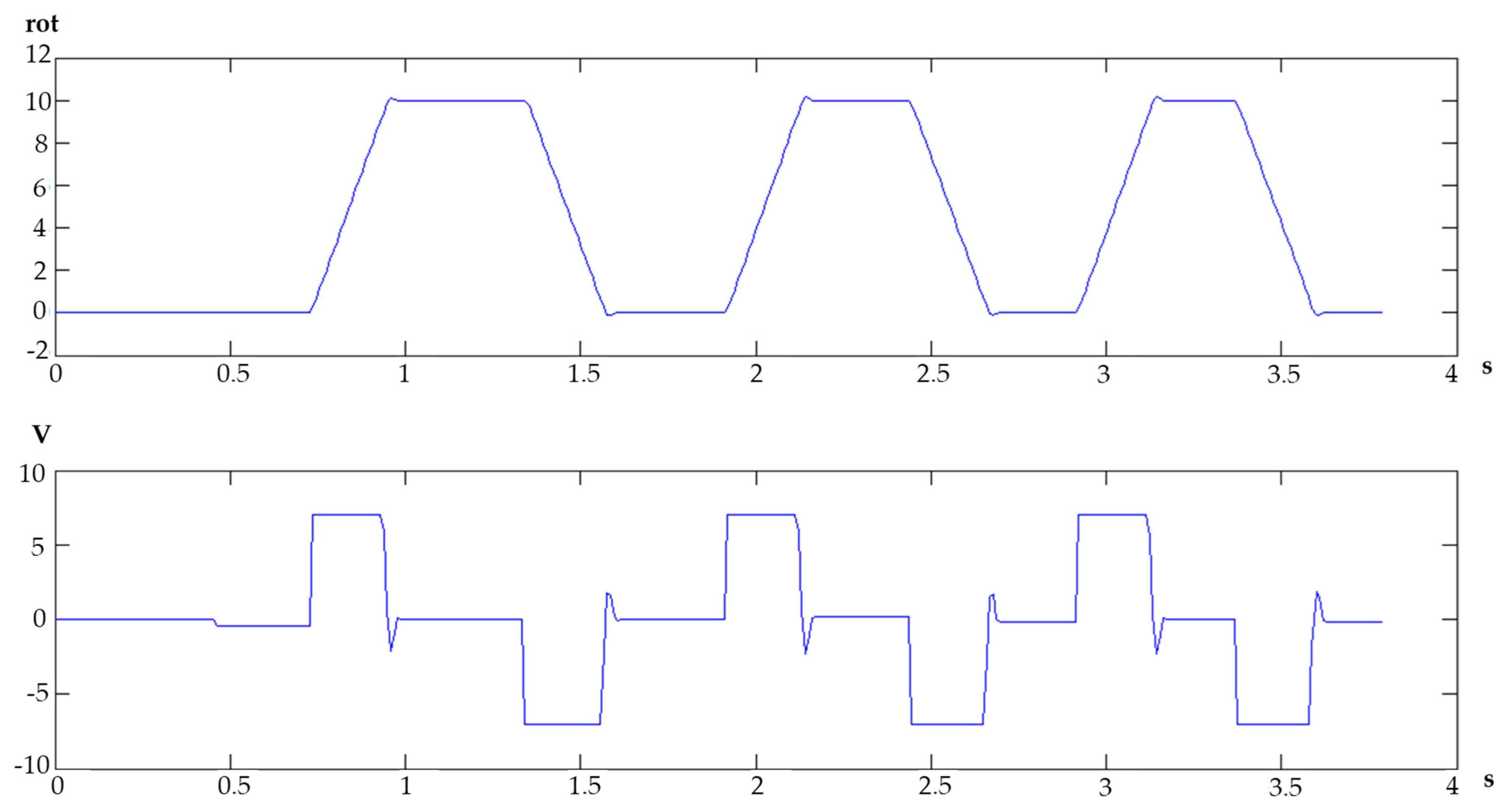
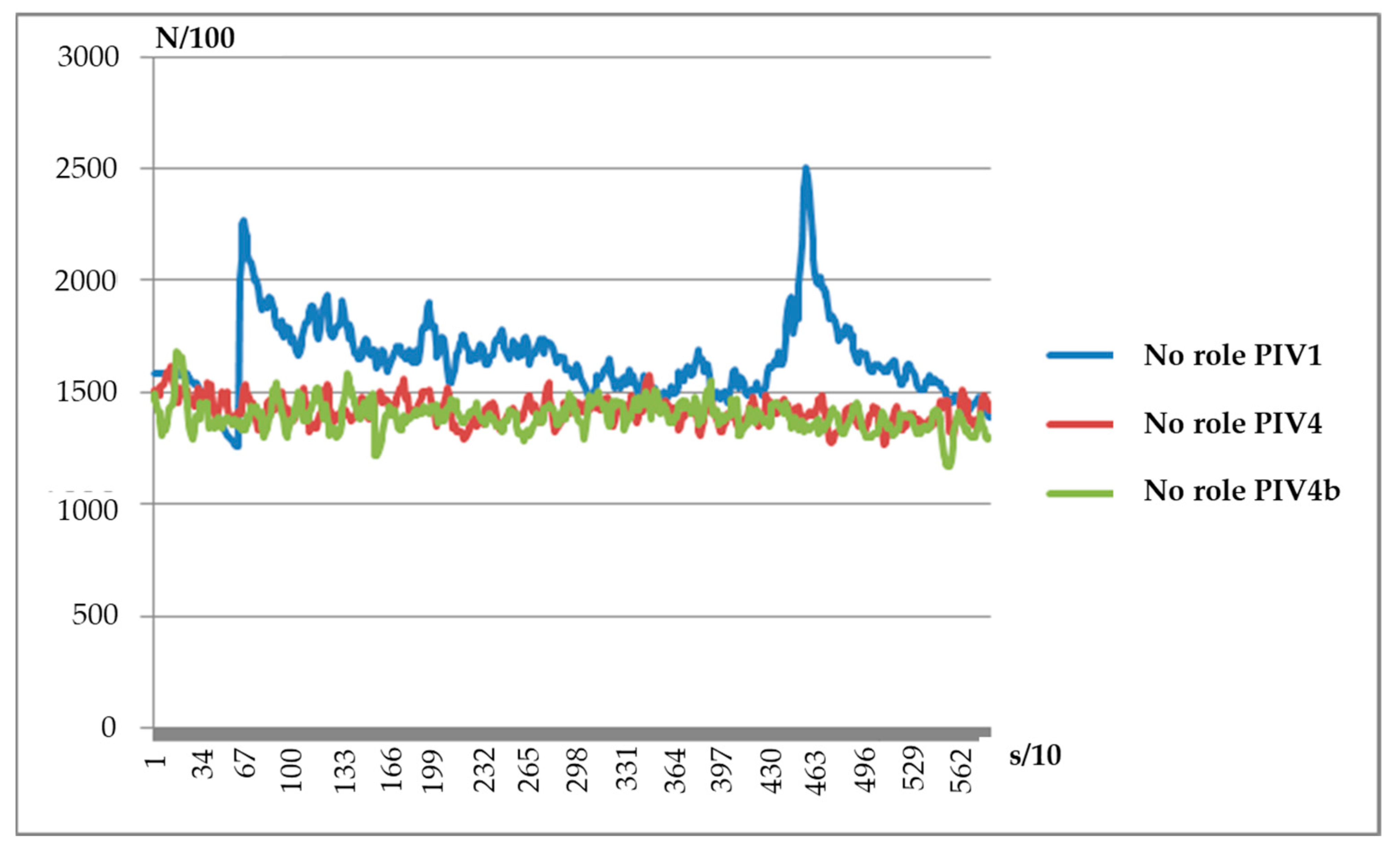
In the first real tests, we considered the source role influence null and the roll was unrolled manually so the tensioning system had to compensate only for the robot trajectory differences. The compensation can be observed in
Figure 17.
From the above figure, it is clear that applying a good formula, as described in the algorithm below, for the control system and having no perturbation, the tensioning can be made very good.
if (comandaRot > comandaRotMaxima)
{
comandaRot = comandaRotMaxima;
}
if (comandaRot < (−1 * comandaRotMaxima))
{
comandaRot = (−1 * 17);
}
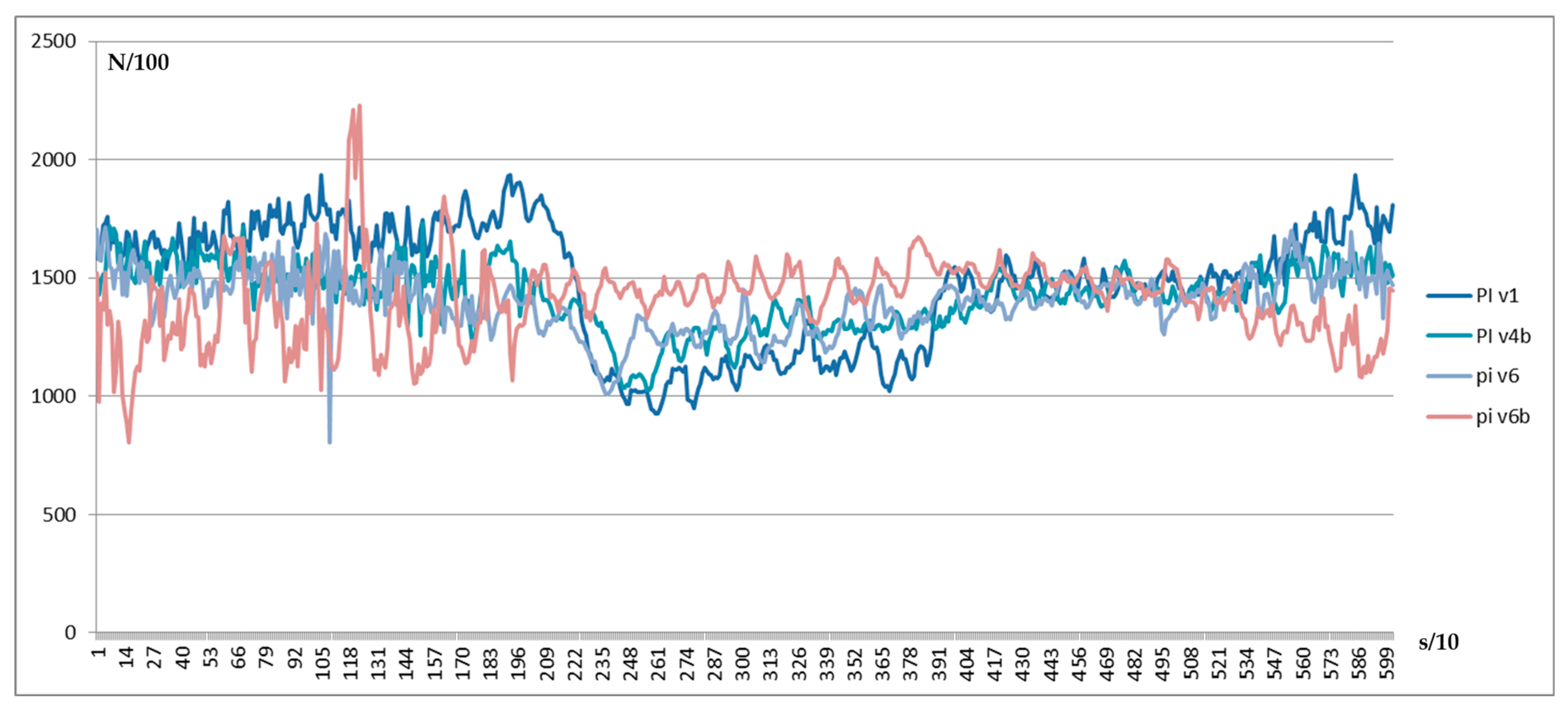
The problem is when the influences from the fiber source role are not null.
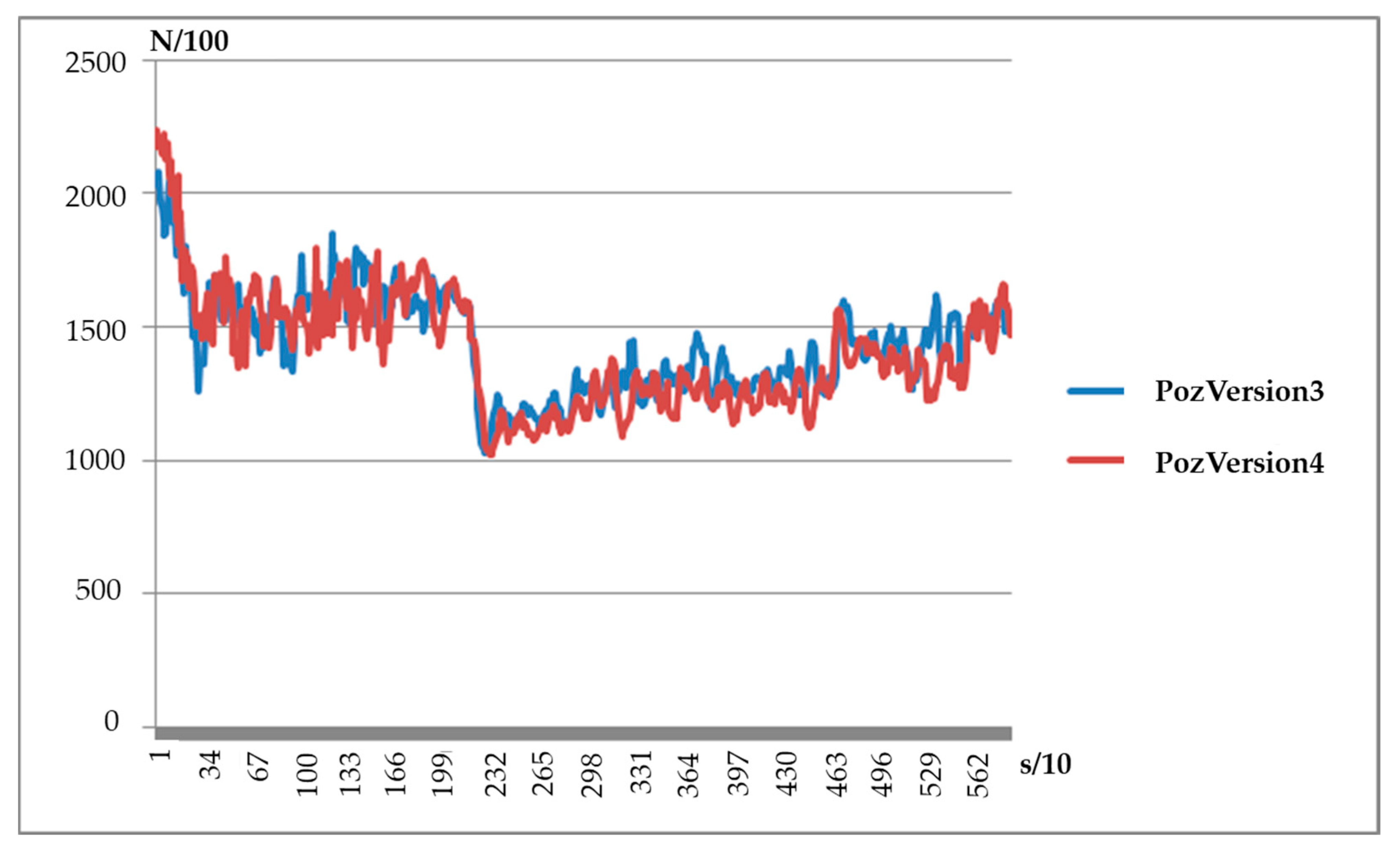
Some adjustments were made to the formula and the results are the following:
In this version, it can still be observed the force drop in the middle of the trajectory. This means the amplifier is not big enough.
Here can be observed a correction on the dropping, but it is still there. This is because the correction is made faster because of the amplifier.
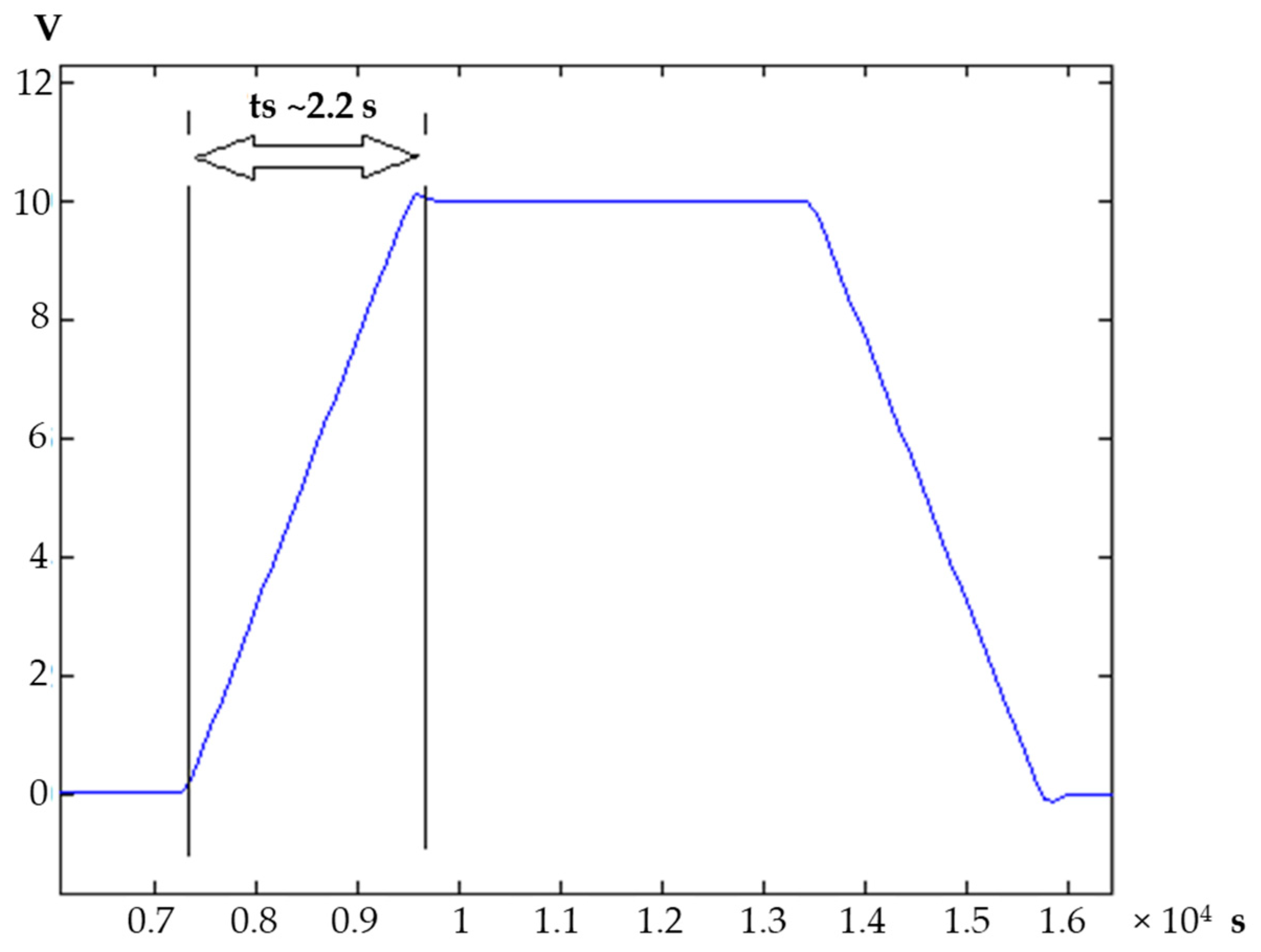
Having the result from the previous test, we consider that an even bigger amplifier will solve the problem. From the measured results, it can be seen the dropping value decreasing and the average value is very close to the reference force set in the parameters (
Figure 18).
4. Results and Analyze
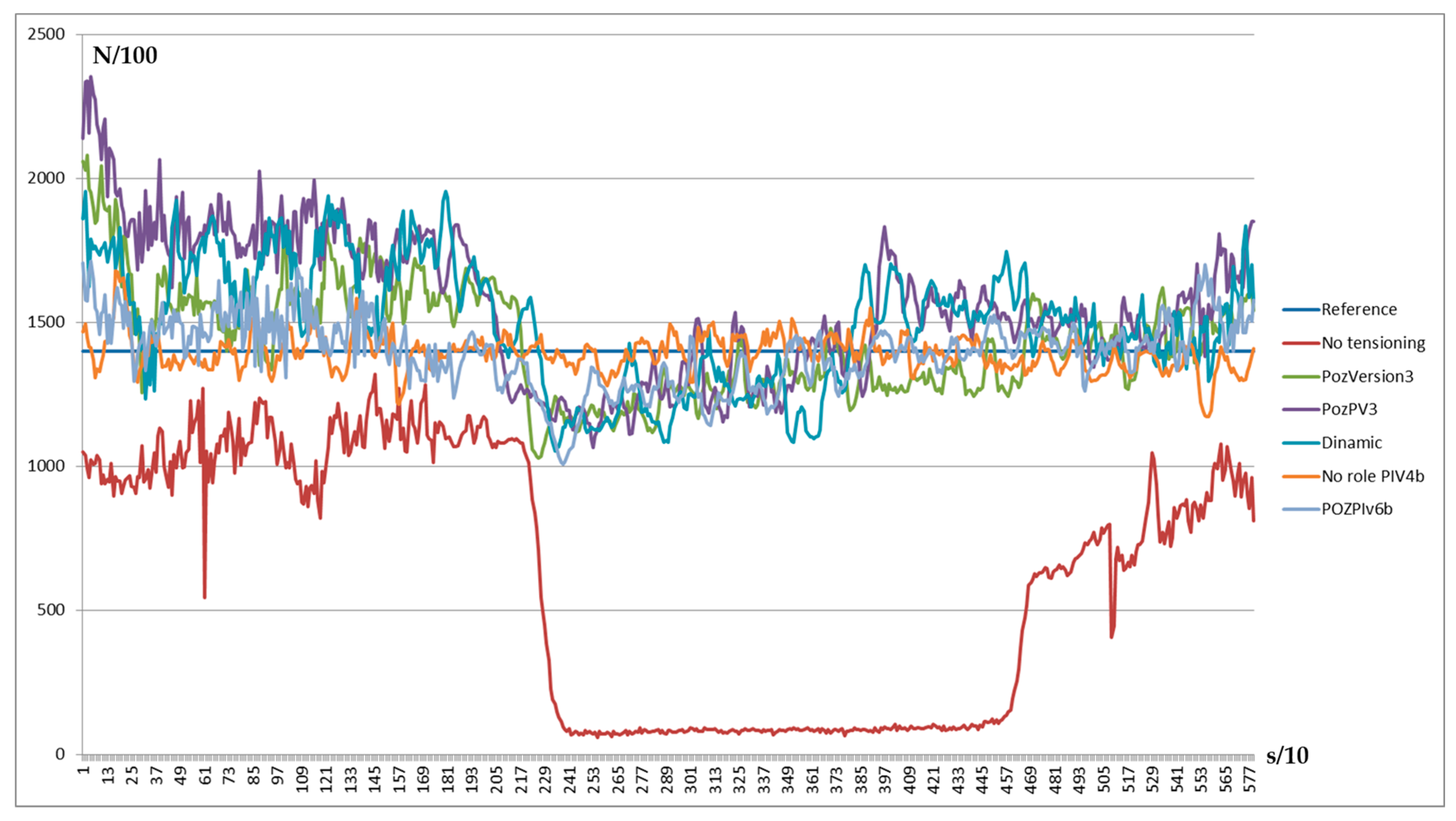
To the previous test were added limits because of the hardware implication of the tensioning device, but also to have better control of the positioning. Because of the limits, big oscillations of the force can appear if the process is not kept under control for the complete time (
Figure 19).
As can be observed, if a big amplifier with limits is used, but also taking into consideration the other constants that a PI controller brings, better results can be obtained compared with the previous tests with a P controller where it is only about the amplifier.
As we mentioned before, all of these tests were made on a matrix with a medium complexity level. With this was possible to observe the influence of the fiber source role in all directions and to compensate for the influence (
Figure 20).
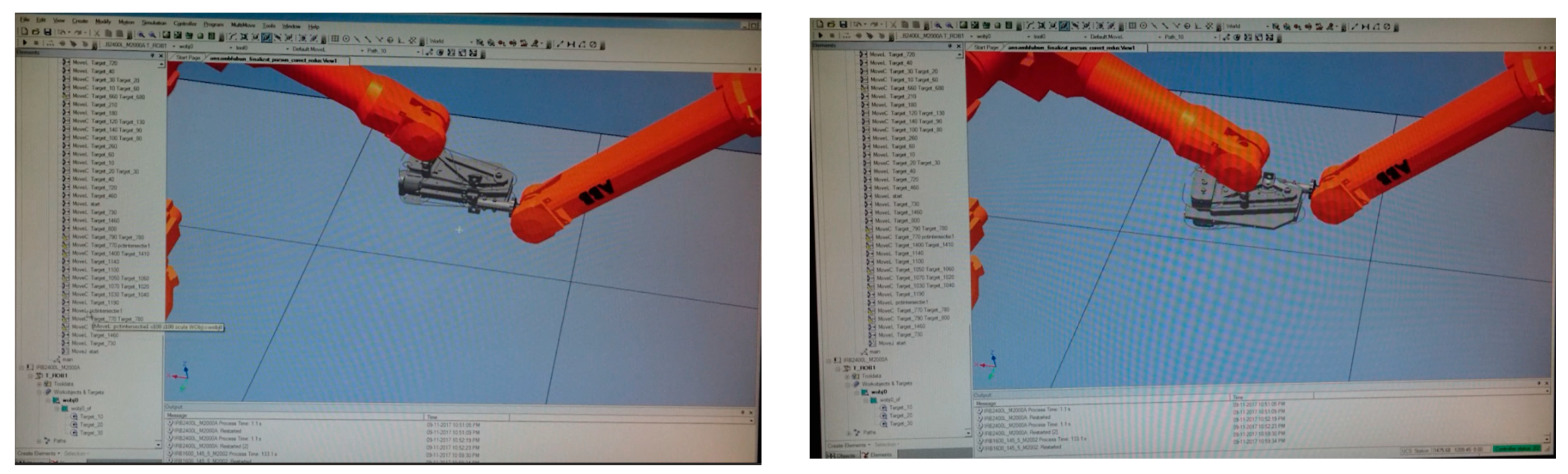
The previous steps and the same tensioning software structure can be used on a complex matrix as well. First of all, the trajectory of the robots and the collaboration model were created virtually using ABB RobotStudio 5.15.02 software. In the simulation, all necessary tools were imported and the speed and the trajectory reachability were tested (
Figure 21).
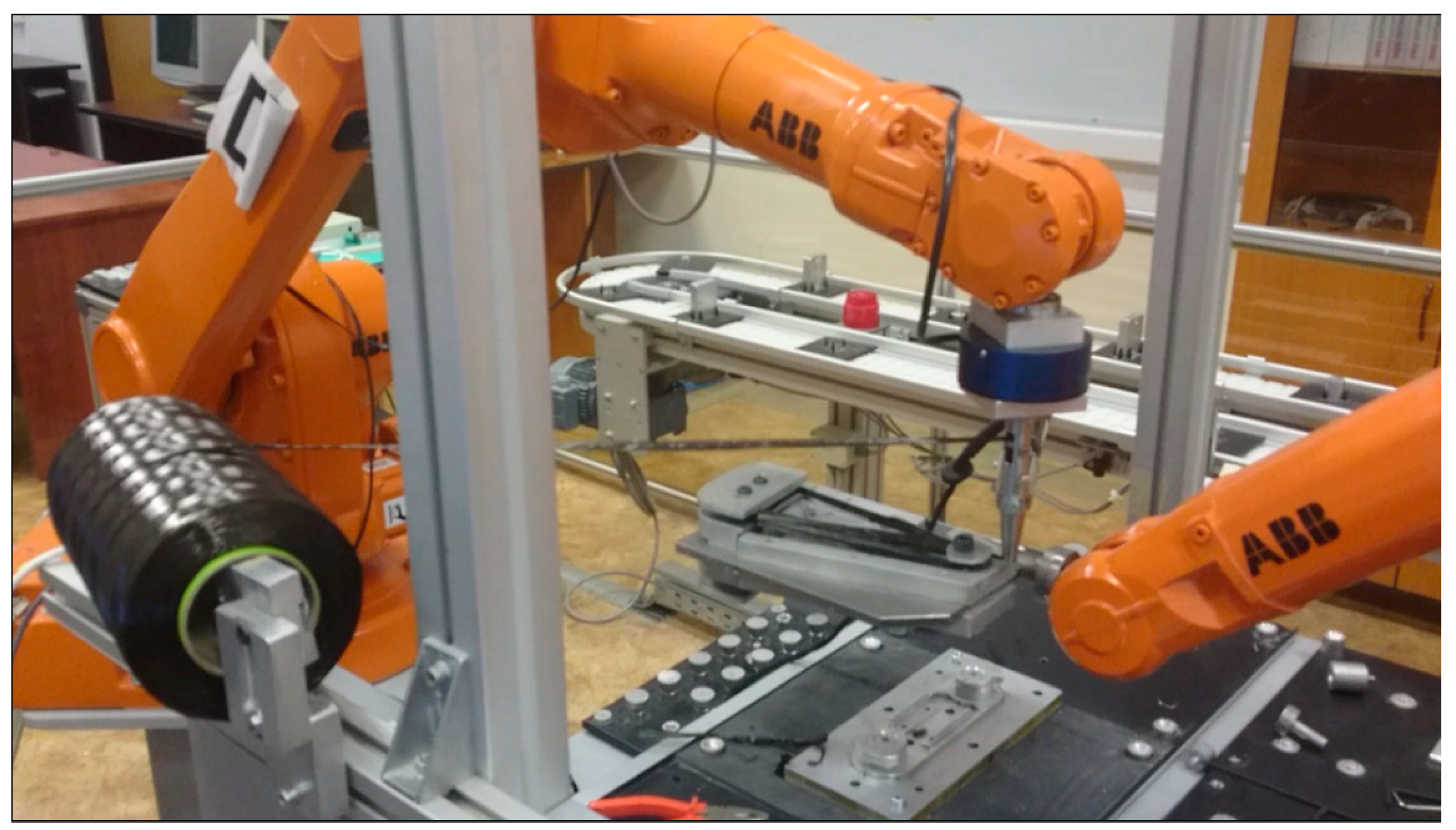
The trajectory identified in the simulation was implemented in the real system and the collaboration instruments were used via the master platform, which was making the connection between the robots and gives the signals between them (
Figure 22).
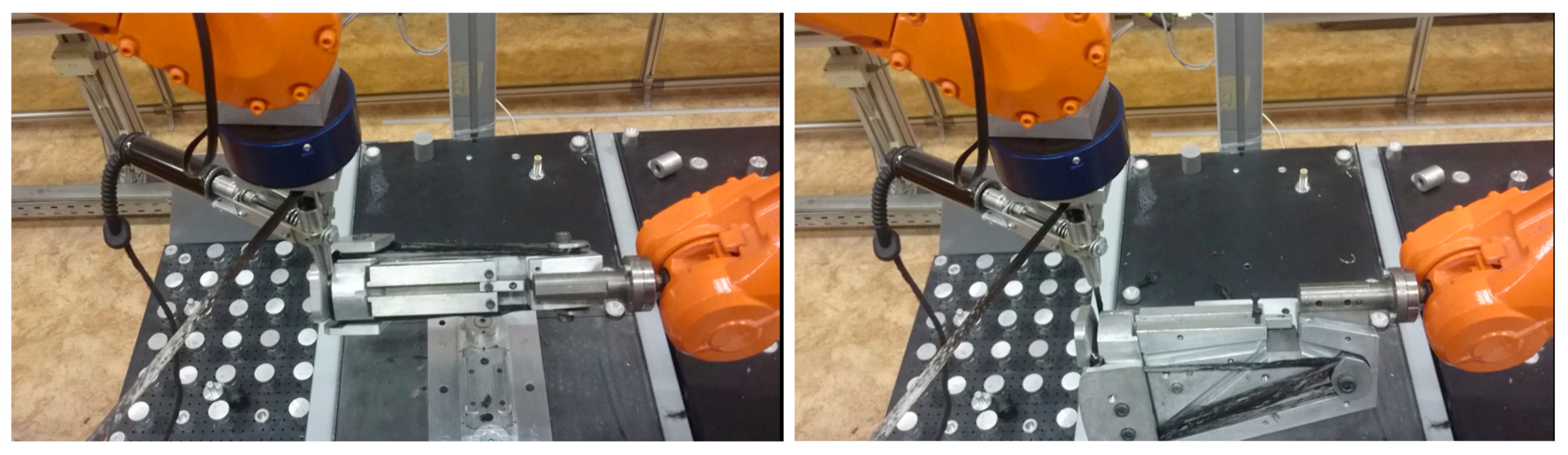
The collaboration process realizes the winding on both sides of the winding die (
Figure 23). The winding die has to be rotated on some points to be able to wind on both sides. There were implemented signals for turn confirmation or position reach-ready to turn.
The advantage of this tensioning device is that, even if it is mounted on a single robot, it is active also when the other robot is creating tension, due to the rotation, meaning the tension is constant including in the rotation moments.
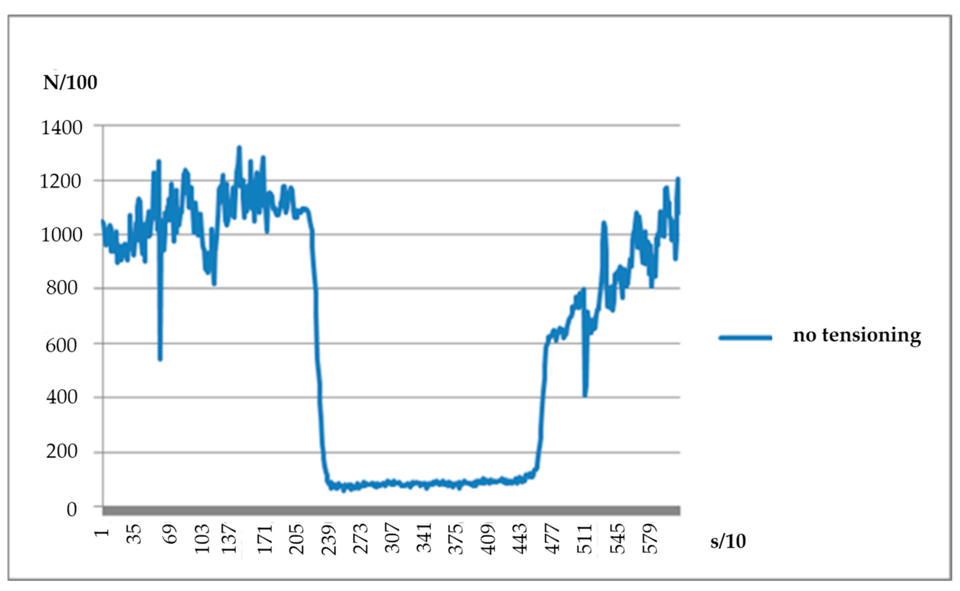
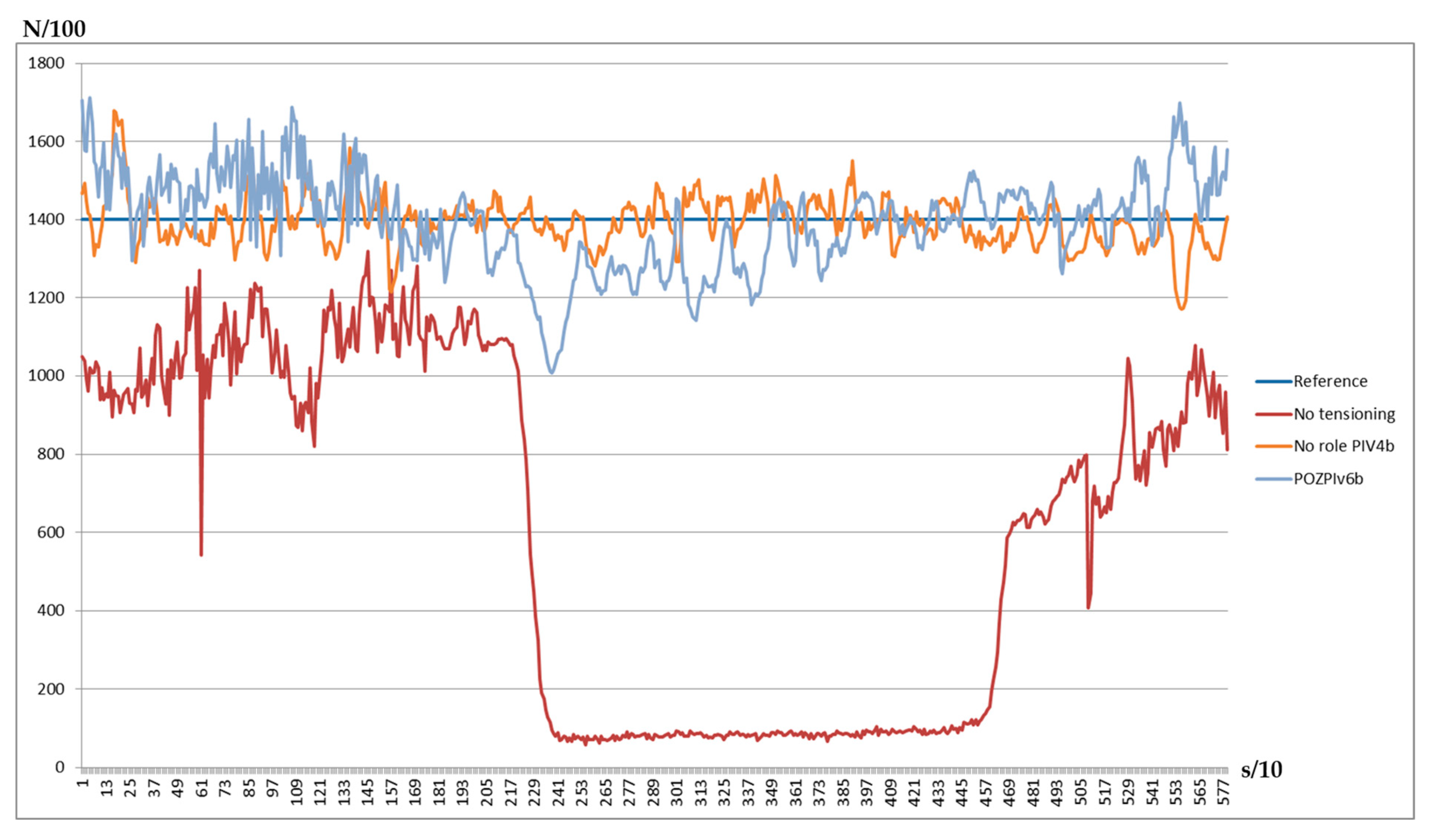
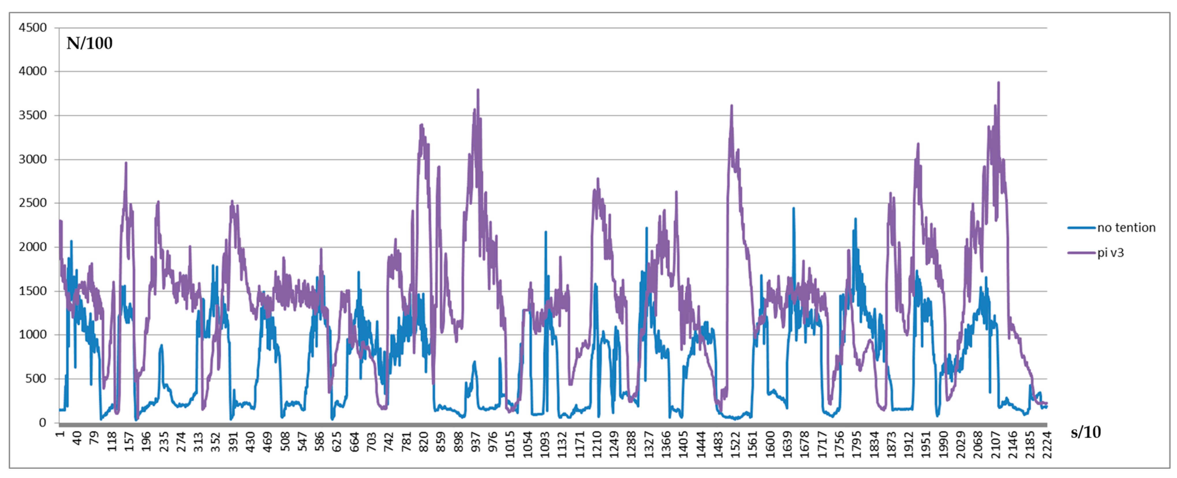
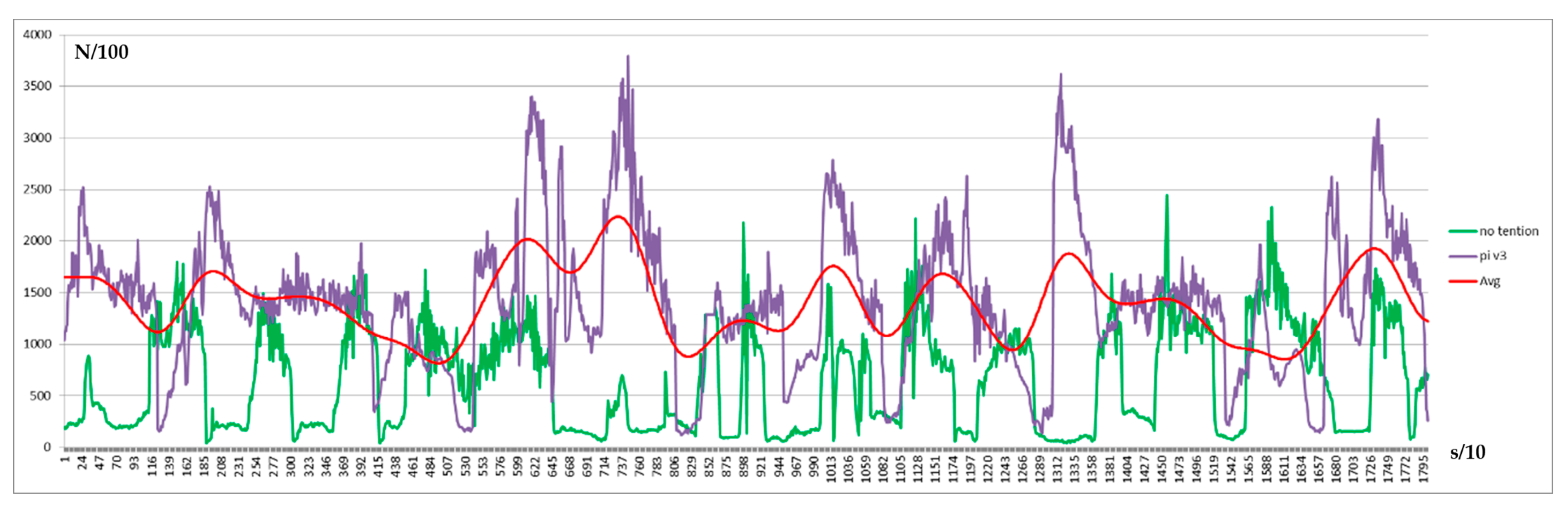
In
Figure 24, the measured force without the role influence and the tensioning device can be seen and the result with both in action, the perturbation, and the tensioning device with a PI regulation implemented. Having the results from the previous implementation, improvements can be made from the mechanical implementation and trajectory corrections. In
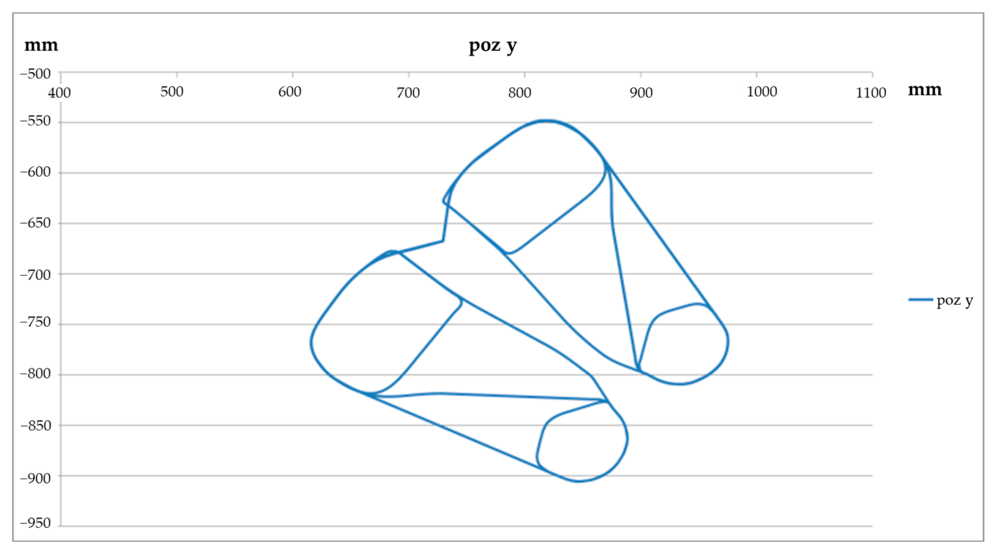
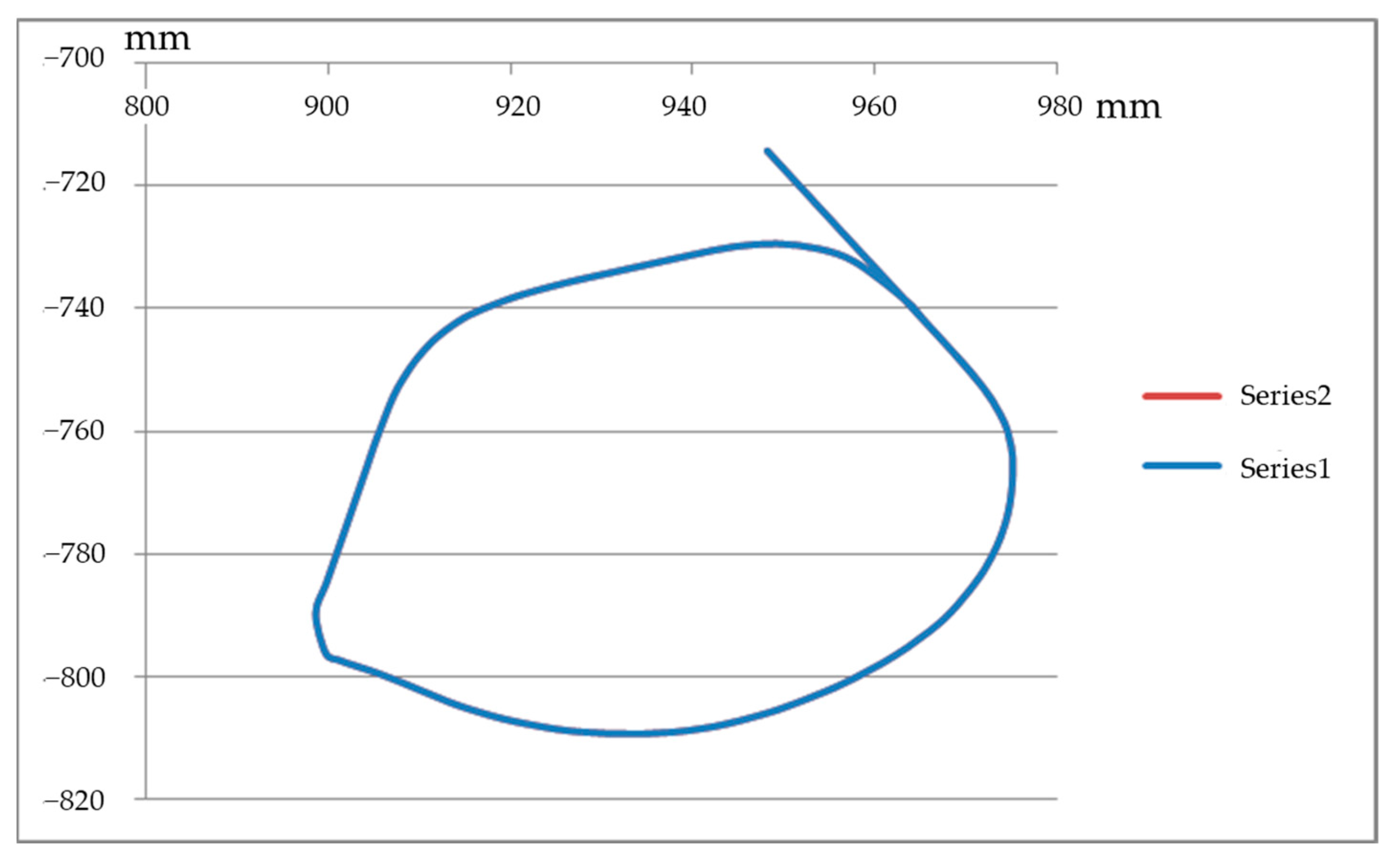
Figure 25, a trajectory path on a single plan is presented.
According to the model, the fiber is tensioned between the matrix and the winding head. If the trajectory is similar to the one presented in
Figure 26, then the tension is loos for a short moment because of the trajectory, but this is recovered after 2–3 measuring points if we apply the control system with a PI formula, as it can be observed in
Figure 27.
5. Conclusions
The experimental tests carried out with one robot, were made to verify and prove the fiber winding methods and models. In the first phase, to determine the nominal values of the stress in the fiber, experimental tests were made to analyze the influences of the frictional forces from the resin supply and impregnation subsystem, on the tension winding process. As a result of these tests, in addition to the fact that the length of the wound fiber decreases with the increase in the value of the tensioning effort, the influence of the resistances in the feeding and impregnation subsystems on the fiber effort generated through the tensioning device integrated into the winding head was highlighted.
From the analysis of the resulting graphs, it is observed that the best results are obtained by implementing the Proportional-Integrator type regulator, which is based on the amplification factor.
The experimental tests performed with two robots were the basis for identifying the nominal parameters of the winding process. After repeating the carbon fiber winding process, under identical conditions, but with different settings of the tension control systems, the best results are obtained with the improved Proportional-Integrator regulator, which ensures the smallest deviation throughout the trajectory, ±0.5 N; the average value of the measured effort being 14.75 N, very close to the proposed target, 15 N.
Starting from the results obtained from the implementation of the carbon fiber tensioning with force adjustment algorithm, for the winding trajectory with a single pass through each point, the trajectory was later extended for the entire length of the deposition path (in multiple layers) of the carbon fiber in the mold, using the same algorithm, with very good results on the entire trajectory.
The implemented carbon fiber tensioning system has the advantage that it can influence the carbon fiber tensioning even during the mold rotation process. The integrated system with collaborative robots can thus be used, together with the carbon fiber tensioning sub-system, supervised by the master controller, without the intervention of the human factor, to ensure a winding that leads to the achievement of the performances im-posed on the final product, defined by the designer.
Following the experimental tests carried out and the results obtained, it is shown that the winding process with two robots and a tensioning system can realize fiber windings with variable tension in molds with complex configurations (3D) of the winding paths to obtain compact structures of the constantly tensioned fiber bundle, according to product requirements.
In summary, within this research, two groups of findings were outlined: the first, concerns the planning, simulation, generation, and implementation of the trajectories of robots to work collaboratively; the second group, is related to the controlled tensioning of carbon fiber using a new tensioning device with a control and command subsystem based on the mathematical winding model.
This winding system with collaborative robots proposed by this research has the potential to step out from the development phase and to be introduced as a standard system for carbon fiber product developers. This is therefore addressed to the large manufacturers of structures made of composite materials who want both a large series production without interruptions and with minimal human influence, but also to reduce the time required for changeovers to a minimum, having prepared the model of the new mold, the tensioning adjustment is automatically done. The limitations of the system can only be seen from the perspective of the need to continue planning and generating the robots’ trajectory in the virtual environment before implementation on the robots, a time-consuming action and with the necessity of highly qualified human resources. However, this limitation appears only when implementing a new part type.


