Article

An Improved Full-Speed Domain Sensorless Control Scheme for Permanent Magnet Synchronous Motor Based on Hybrid Position Observer and Disturbance Rejection Optimization

College of Mechanical and Electrical Engineering, Shihezi University, Shihezi 832003, China
*
Author to whom correspondence should be addressed.
Electronics 2023, 12(18), 3759; https://doi.org/10.3390/electronics12183759
Submission received: 3 August 2023 / Revised: 1 September 2023 / Accepted: 4 September 2023 / Published: 6 September 2023

Abstract

:
A sensorless control algorithm not only reduces the cost of a permanent magnet synchronous motor (PMSM) system, but also broadens its application scope. Expanding speed threshold and enhancing dynamic performance are crucial aspects. To optimize the adaptability of observers and the immunity of the controller in a full-speed domain, an improved sensorless control scheme for a PMSM based on a hybrid position observer and disturbance compensation is proposed. Firstly, the precise detection of the initial position and the scheme of starting with the load at any position are proposed based on high-frequency rotation injection, magnetic pole direction calibration and square-wave high-frequency injection (HFI). Secondly, a higher-order sliding mode observer (HSMO) is designed to improve high-speed observation performance by introducing an extended electromotive force (EEMF). Correspondingly, a speed controller called PI plus is developed utilizing a reverse control algorithm and the observed disturbance quantity, which further enhances the system’s disturbance rejection capability. Subsequently, a linearly weighted observer switching method and a linear signal withdrawal scheme are proposed to suppress torque and speed oscillations in medium-speed threshold. Furthermore, a normalized linear extended state observer (LESO) is designed to enhance rotor information estimation accuracy and enable the observation of unknown disturbances in full-speed thresholds. Finally, the effectiveness of the proposed sensorless control system is tested through experiments involving variations in speed, load, and parameter. The experimental results indicate that the proposed sensorless strategy is capable of achieving a loaded start. The designed observer switching strategy and the scheme of injection signal withdrawal contribute to a smoother acceleration process. Furthermore, load variation test results at high-speed thresholds demonstrate that the proposed controller can reduce speed drop by 45 rpm compared to a traditional PI. Additionally, the results of parameter variation testing validate the observer’s robustness in the disturbances of ψ f within the range of ±0.3 pu.

1. Introduction

Permanent Magnet Synchronous Motors (PMSMs) offer significant advantages in torque stability, power density and mechanical properties. Strictly, accurate rotor position and speed are important prerequisites for the effective closed-loop control of a PMSM. Generally, encoders that are optical, magnetic, rotary, etc. are employed to directly detect rotor information. However, the installation, maintenance, size, and cost of mechanical measuring equipment deserve further consideration. Particularly, the reliability of the measurement results and the cost of the equipment under severe interference can be the primary metrics for a PMSM. Therefore, to solve the problems of cost, space, installation and accuracy caused by measurement equipment, many sensorless control schemes have been researched and proposed, mainly including model-based and signal injection-based methods [1,2,3,4]. In Table 1, the contributions and shortcomings of some related studies are summarized and analyzed.
In recent studies, the signal injection method has had higher reliability at low speeds, while the model-based method has shown unique advantages at high speeds [12,13]. However, it is still difficult to find a reliable strategy that comprehensively covers the entire speed threshold. Therefore, the strategy of a composite sensorless control scheme has also been the subject of further research by many scholars. Among them, the scheme of combining I/F with a model-based method is widely adopted, which can avoid the problem of inaccurate observation caused by the low signal-to-noise ratio of model-based methods at low speed [14]. However, some disadvantages are still unavoidable for this scheme. On the one hand, the self-balancing range for power angle is one of the necessary conditions to ensure the stable operation of the motor. On the other hand, I/F control lacks a closed loop of speed, which hardly guarantees precise speed control. In addition, it is also a common solution to transition to the high-speed threshold with a V/F control that benefits from a simple open-loop control approach [15]. However, parameter coupling makes it only suitable for situations with low dynamic performance. In order to further improve the dynamic performance in the low-speed section, the scheme based on signal injection is usually applied to realize speed closed-loop control. The work in [16] proposes a composite sensorless control scheme for a synchronous reluctance motor with effective flux linkage and high-frequency injection. However, the work in [17] points out that the accuracy of the flux linkage observer is affected by the dead zone of the inverter. Therefore, other model-based schemes, such as the Luengerber observer, EKF and sliding mode observer (SMO), are also applied to rotor information identification in the high-speed range [5,6,7]. It is worth noting that the Luengerber observer has strong parameter sensitivity, which further affects the stability of the observer. Although EKF can reduce the dependence on model parameters, it requires a large amount of computation, which makes it difficult to apply to fixed-point MCUs. An SMO with a simple structure and strong robustness can optimize the above problems. However, it is necessary for traditional SMOs to use a low pass filter (LPF) to filter the back EMF, which can introduce phase delay. In order to improve the performance of SMOs, some scholars adopt continuous functions to replace symbolic functions to suppress chattering, such as Sigmoid ( · ) and fal ( · ) , etc. [18,19]. However, this method also weakens the advantage of variable structure control. In addition, designing high-order reaching rates can also play an effective role in optimization. The work in [20,21] designs a second-order SMO by adopting a super-twisting algorithm that effectively suppresses the chattering phenomenon. Experiments prove that the second-order SMO has a positive effect on suppressing disturbances, improving robustness and immunity.
Moreover, the method of rotating high-frequency injection (HFI) can only converge with a saliency machine in the conventional signal injection scheme. Although the method of pulsating HFI can be extended to the surface-mounting PMSM (SPMSM), the use of filters to separate high-frequency and low-frequency response currents inevitably introduces phase delay [8]. Compared to these two schemes, the method of square-wave HFI can effectively avoid the use of filters by adopting simple sum and difference calculations. Meanwhile, the injection of high-frequency square waves makes the saturated saliency more remarkable, which greatly improves the recognition accuracy [22].
To achieve stable load operation in the full-speed range, initial rotor position detection (IPD) at zero speed and the switching process of the observers in the medium-speed range are also crucial [23,24]. Usually, an inaccurate initial rotor position may cause a surge in the starting current, which can even lead to reverse rotation or failure to start up. Correspondingly, the method of rotor pre-positioning can result in undefined rotation, which has great limitations for the motor with a load to obtain an accurate initial position [9,10]. Furthermore, methods such as pulsating injection, square-wave injection and six-pulse positioning can effectively avoid the problem of rotor movement. However, six-pulse positioning can achieve an identification accuracy of ±15°, and the calculation process of the square-wave and pulsating injection is dependent on the injection frequency and amplitude. Therefore, it is necessary to propose an IPD scheme with less sensitive parameters to guarantee the possibility of starting with a load in any position. In [25], the nonlinearity of d q inductance is further considered, which further improves the identification accuracy of square-wave voltage injection.
In addition, when the motor is in the medium-speed range, it is necessary to select a reliable observer to maintain the most accurate identification results [11,26]. To realize the smooth switching of different observers, commonly used switching schemes include the hysteresis switching method, the weighted switching method, etc. Among them, the hysteresis switching method can produce greater speed and torque jitter compared to weight switching due to the inconsistency of identification results from different observers. What is more, less attention has been paid to the method of injection signal exiting at present. Improper exiting of injected signals may further increase system chatter. In addition, when entering the stable state of the high-speed threshold, further attention must be paid to the system’s ability to suppress load disturbances. A disturbance observer is designed in [27] to observe the unknown disturbance of the system, so that the velocity response performance can be improved. Therefore, it is also worth proposing a disturbance compensation method in the rotor information calculation part of the observer to optimize the controller’s ability to resist load disturbances.
Inspired by the above, this paper first designs a sensorless control scheme in the full-speed range. Here, a method of rotating voltage HFI is designed in the zero-speed stage to reduce the impact of injection amplitude, frequency and motor parameters. Secondly, an NS pole judgment scheme is designed to correct the results of the rotor identification to ensure reliable convergence of the observer. Then, the extended back electromotive force (EEMF) is introduced into the state variable to construct a high-order sliding observer (HSMO) to suppress the phase lag and output chatter problems of the traditional SMO. In addition, a linear extended state observer (LESO) is designed to acquire rotor information and system disturbance. On this basis, a novel PI controller is designed, called PI plus, by considering the integral saturation phenomenon and insufficient anti-disturbance performance of traditional PI controller. Here, the reverse control link and a disturbance feed-forward compensation link are established. Finally, an observer switching algorithm based on linear weighting and a linear exit scheme of the injected signal are designed to achieve more stable composite control.
The innovation points of this paper are refined as follows: (1) Combined with the proposed IPD, NSD, square-wave HFI and HSMO, a sensorless control system in the full-speed threshold is designed. (2) A zero-speed rotor position identification scheme for high-frequency rotational injection is introduced to reduce the sensitivity of injection amplitude and frequency during the stage of IPD. (3) A linearly weighted switching scheme for observers and a linear exit scheme for injected signals are designed to optimize system dynamic performance in the observer transition phase. (4) An HSMO is designed to avoid the phase delay caused by LPF at high speed. (5) An LESO is designed to improve the solution accuracy and achieve disturbance observation. Based on this, combined with the reverse control algorithm and disturbance observation results, a PI plus controller with functions of disturbance compensation and anti-integral windup is designed to optimize the performance of the speed controller.
The remaining portion of this article is organized as follows: The mathematical models of PMSM, square-wave HFI, and HSMO are derived in Section 2. In Section 3, the following schemes are designed: the zero-speed rotor position identification scheme, the rotor information estimation scheme based on LESO, the linear weighted observer switching strategy, and the scheme for linearly deactivating the injection signal. Simultaneously, a speed controller called PI plus with the functionalities of disturbance compensation and integral anti-windup is designed to optimize the system’s dynamic performance. In Section 4, a typical PI parameter tuning scheme is presented. Subsequently, performance tests are conducted in various operating conditions, including full-speed operation, load variations, speed changes, and parameter perturbations. Finally, the work is summarized in Section 5.

2. Basic Mathematical Model of PMSM Sensorless System

2.1. Mathematical Model of PMSM

The voltage equation of PMSM in the dq-coordinate system is described in Equation (1), which facilitates the establishment of decoupled control and the sensorless observer models.
u d = R s i d + L d d d t i d w e L q i q u q = R s i q + L q d d t i q + w e L d i d + w e ψ f
where i d / q , u d / q and L d / q are written as current, voltage and equivalent inductance in d q f r a m e , respectively. R s is defined as the stator resistance. w e and ψ f represent rotor angular velocity and flux linkage. From Equation (1), the field-oriented control scheme is adopted to decouple the control system. The stator voltage ( u d and u q ) in the dq-axis is reconstructed in Equation (2).
u d = u d + w e L q i q u q = u q w e L d i d w e ψ f
From Equations (1) and (2), the open-loop transfer function of the PMSM in the dq-coordinate system can be derived in Equation (3).
G d q i s = 1 / L d q s + L d q
In Equation (3), s represents the Laplace operator. To achieve stable torque and speed control across the entire speed range, it is usually necessary to introduce a speed–current dual-loop control framework.

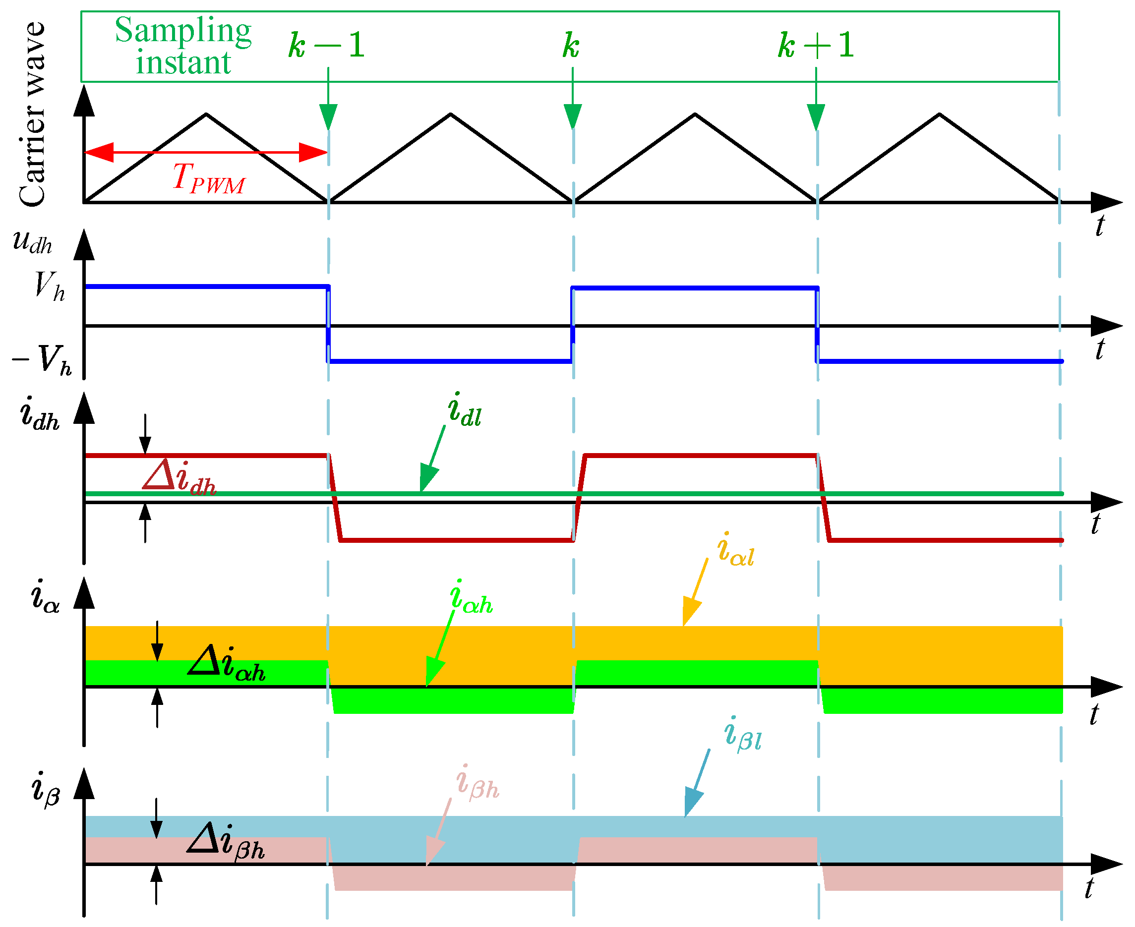
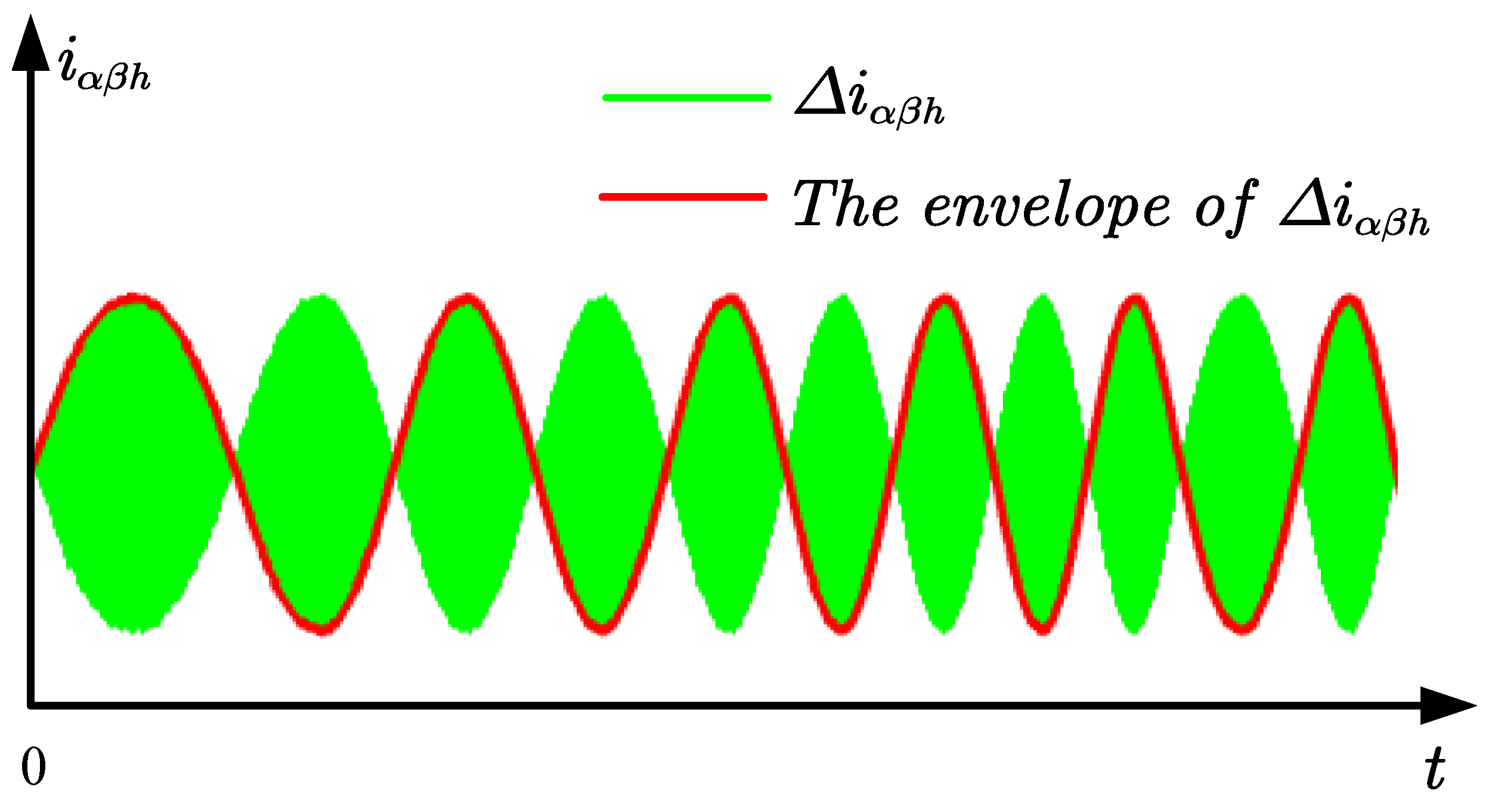
2.2. Mathematical Model of Square Wave HFI Observer

Generally, a sensorless scheme based on signal injection has higher accuracy at low speeds. In order to facilitate the separation of high- and low-frequency response currents, a square wave frequency with 1 / 2 T P W M Hz is usually selected, which makes the reactance much larger than other impedance parameters during the high-frequency response. Therefore, the current response equation of high frequency for the PMSM can be simplified to Equation (4).
i d h i q h = L d h d d t 0 0 L q h d d t 1 u d h u q h
where i d / q h and u d / q h represent the high-frequency injection voltage and the high-frequency excitation current, respectively. L d / q h is defined as the stator inductance in the high-frequency excitation loop. The injection voltage is expressed in Equation (5).
u d h = V h , The k t h carrier period V h , The k + 1 t h carrier period u q h = 0
where V h represents the amplitude of the injected square wave. From Equation (5), the square wave of equal amplitude, equal width and reverse injection in the d-axis ensures that the mean value on the time scale is 0, which can further reduce the influence of the injected signal on torque. The response current during square-wave injection can be briefly described in Figure 1.
Practically, the injected signal is applied in the estimated rotated frame ( d ^ q ^ -frame). It is necessary to transform the high-frequency response signal from the d ^ q ^ -frame to the two-phase stationary coordinate system ( α ^ β ^ -frame) for rotor position identification, which is given in Equation (6). Here, θ ˜ e represents the angle between the d ^ q ^ -frame and the d q -frame, which is denoted in Equation (7).
i α h i β h = cos θ e sin θ e sin θ e cos θ e L d h d d t 0 0 L q h d d t 1 cos θ ˜ e sin θ ˜ e sin θ ˜ e cos θ ˜ e u d h u q h
θ ˜ e = θ e θ ^ e
In Equations (6) and (7), i α / β h represents the high-frequency excitation current in the two-phase stationary coordinate system. θ ^ e is defined as the estimated rotor electrical angle. When θ ˜ e 0 is satisfied, the high-frequency response current in the α ^ β ^ -frame is derived in Equation (8) by combining Equations (6) and (7), which contain the rotor position information, as shown in Equation (9).
i α h i β h = u d h L d h cos θ e sin θ e d t
cos θ e sin θ e = L d h u d h d d t i α h i β h
From Figure 1, differential signals of low- and high-frequency currents can be effectively separated from Equation (10). In this way, the phase delay phenomenon from LPF can be avoided, which makes the identification of rotor information more accurate.
i α l = i α k + i α k 1 2 i β l = i β k + i β k 1 2 Δ i α h = i α k i α k 1 2 Δ i β h = i β k i β k 1 2
where k represents the timing of current adoption. After that, the rotor position information can be effectively obtained by extracting the envelope curve of the high-frequency response current ( s i g n u d h Δ i α β h ), which is shown in Figure 2. Note that the fundamental frequency and high-frequency response signal exhibit similarity in high-speed scenarios such that the signal separation method is not applicable.

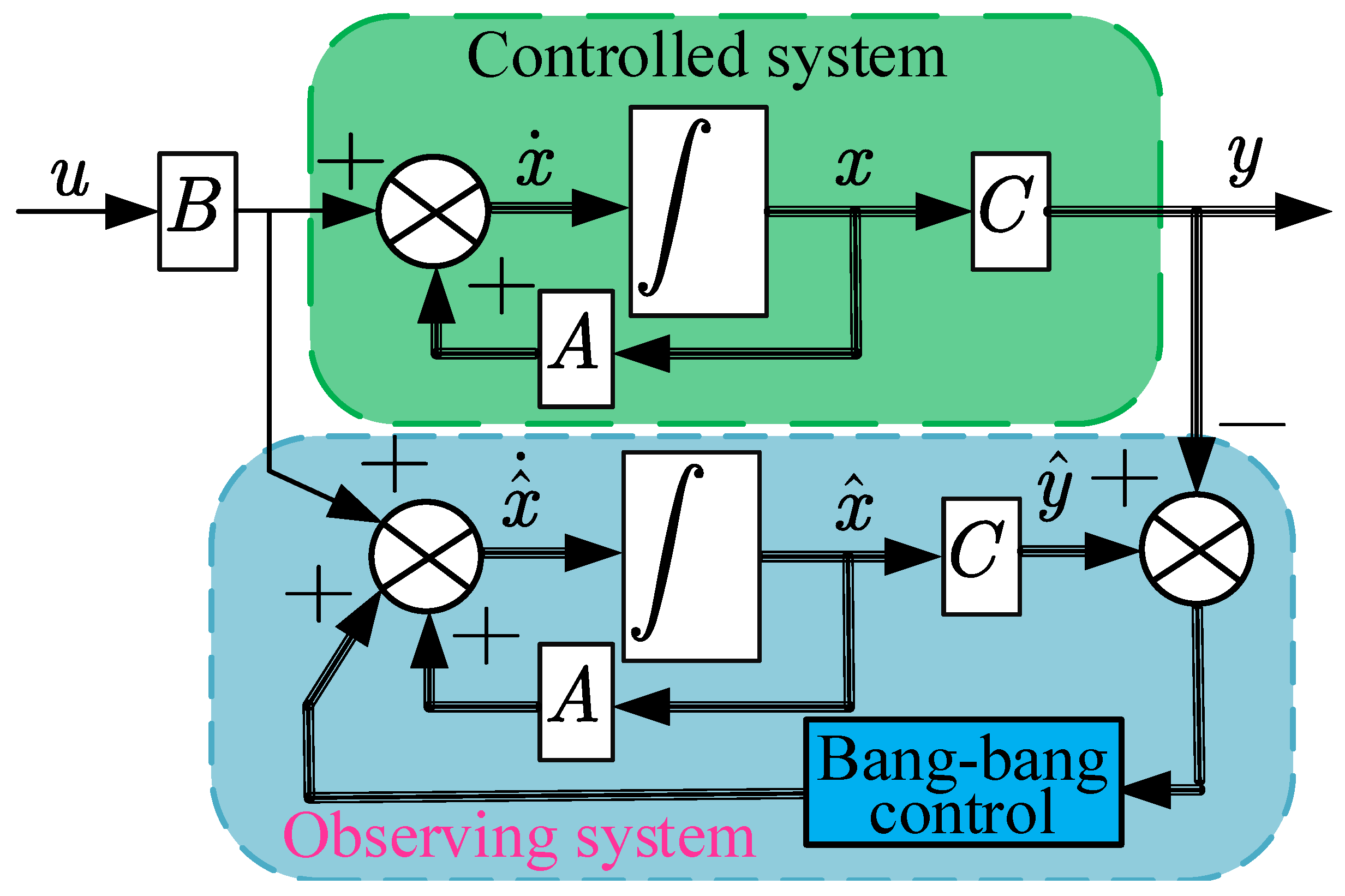
2.3. Mathematical Model of HSMO

In the high-speed operation stage of the PMSM, the increase in the electrical frequency can lead to inaccurate high-frequency current response equations, which affects the reliability of rotor information identification. Equally, long-term signal injection can also cause the increase in torque ripple and energy loss, as well as changes in motor parameters. The robustness of the observer should be emphatically considered, particularly after the motor has reached its rated high-speed operating state. Benefiting from the strong robustness of SMO, the sensorless scheme utilizing SMO should be a better choice. In addition, in order to suppress chatter caused by the discontinuous phase and the phase delay caused by LPF, the introduction of back EMF for an HSMO can further improve the accuracy of rotor information identification.
By considering the versatility of a PMSM, the voltage equation is reconstructed by introducing the EEMF in the α β frame, which is described in Equation (11).
u α u β = R s + L d d d t w e L d L q w e L d L q R s + L d d d t i α i β + e α _ e x t e β _ e x t
In Equation (11), e α _ e x t and e β _ e x t are defined as EEMF in the α β frame, which are denoted in Equation (12).
e α _ e x t e β _ e x t = 0 L d L q w e i d d d t i q + w e ψ f sin θ e cos θ e
where u α / β represents the stator voltage in the two-phase stationary coordinate system. w e is a constant in a control cycle. Therefore, Equation (12) can be further deduced in Equation (13). Note that it is suitable to surface, interior and reluctance machines.
e ˙ α _ e x t e ˙ β _ e x t = w e e β _ e x t e α _ e x t
On the basis of the Luengerber observer, the approach rate design HSMO uses bang-bang control instead of proportional control; its block diagram is shown in Figure 3. Here, the correction link is introduced so that the observed state variable x ^ can converge to the actual state variable x.
From Equations (12) and (13), the equation of the HSMO with the state variables of i α , i β , e α _ e x t and e β _ e x t is given as Equation (14):
i ^ ˙ α i ^ ˙ β e ^ ˙ α _ e x t e ^ ˙ β _ e x t = R s L d w e L d L q L d 1 L d 0 w e L d L q L d R s L d 0 1 L d 0 0 0 w e 0 0 w e 0 i α i β e α _ e x t e β _ e x t + 1 L d 0 0 0 0 1 L d 0 0 u α u β 1 L d k 0 m 0 0 k 0 m s i g n i ^ α i α s i g n i ^ β i β
where “ x ^ ” stands for the observation of x. EEMF ( e α _ e x t and e β _ e x t ) contain rotor position information and can be effectively observed when the HSMO converges. Therefore, the rotor position information can be efficiently resolved. It is worth noting that the bang-bang control term is integrated, which not only avoids the phase delay caused by LPF, but also suppresses the chatting phenomenon.

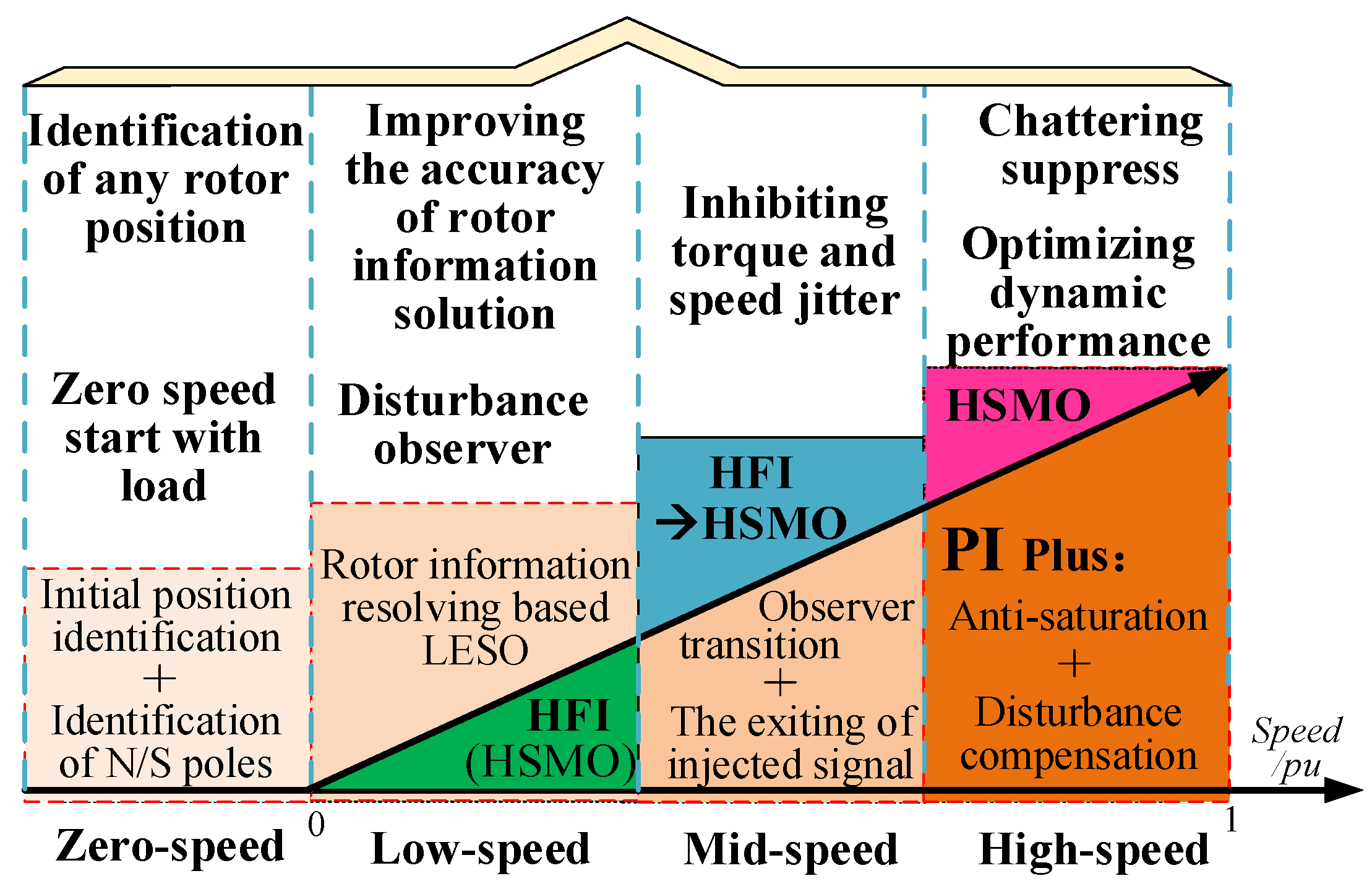
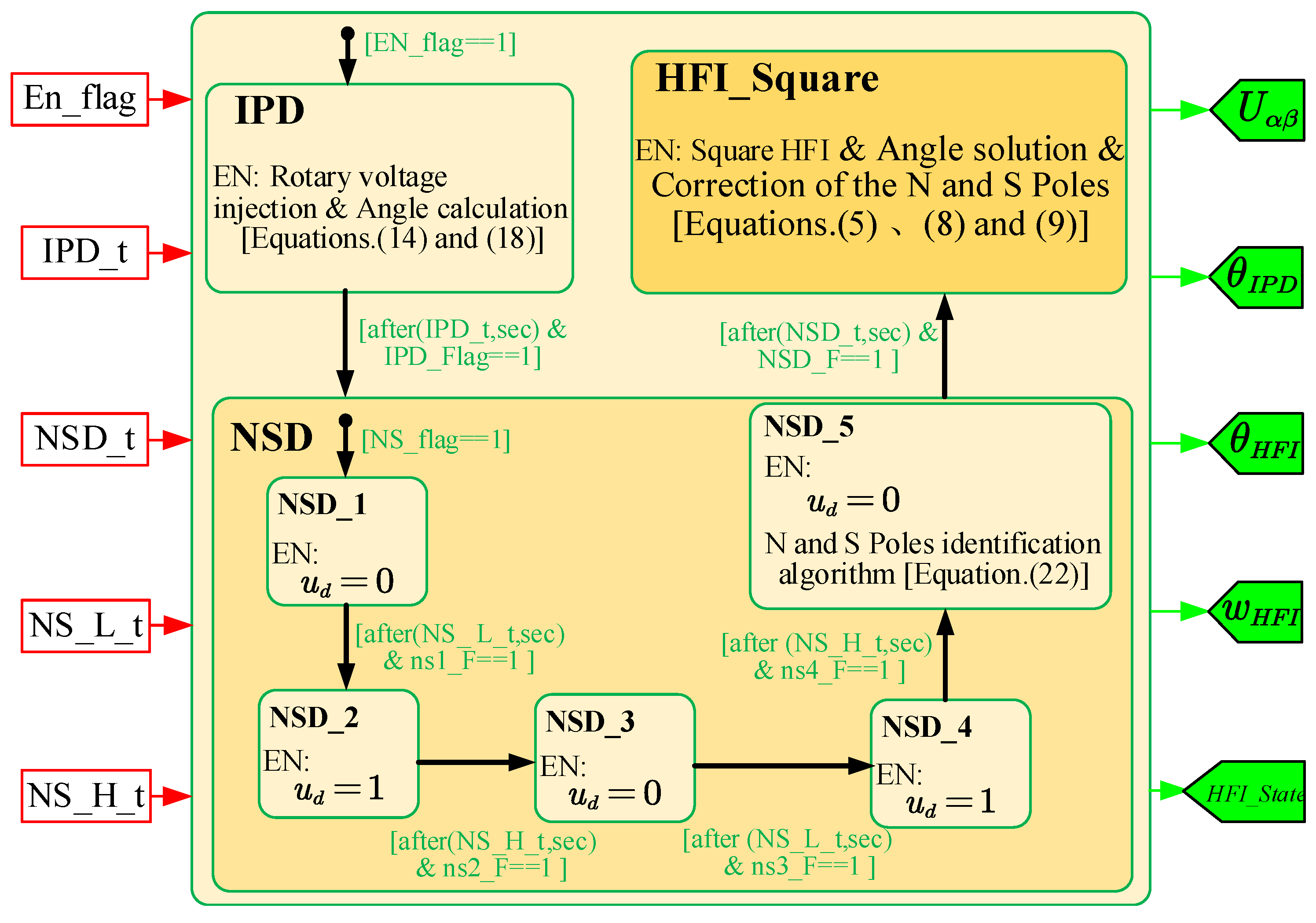
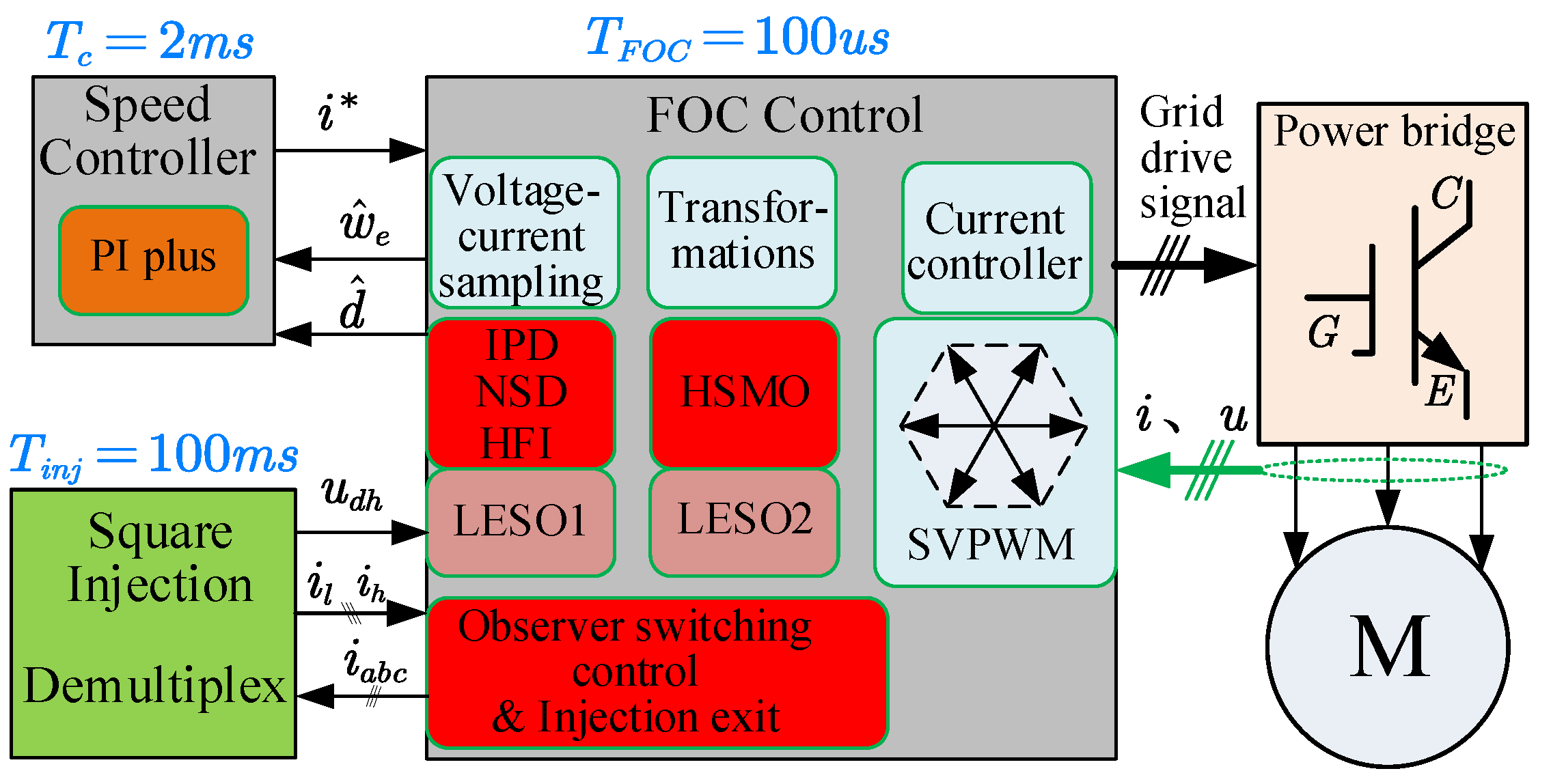
3. Proposed Full-Speed Domain Sensorless Scheme

To realize sensorless control in the full-speed range, a composite sensorless scheme of square-wave voltage HFI and HSMO is proposed. On the one hand, The signal injection method can compensate for the issue of low back-EMF signal-to-noise ratio in an HSMO at low speeds. On the other hand, the high-speed range uses an HSMO to avoid the problems of inaccurate high-frequency excitation signals and high energy consumption. Among them, the smoothness in the switching process of different observers also has a great influence on the running state of the motor. What is more, the anti-load disturbance performance and the accuracy of rotor position identification are also crucial in the process of sensorless operation. In addition, the ability to start with a load at zero speed is also required for many sensorless control applications in any position. Therefore, the entire sensorless control scheme is divided into four speed domains for specific analysis, which are summarized as zero speed, low speed, medium speed and high speed and are described in Figure 4.

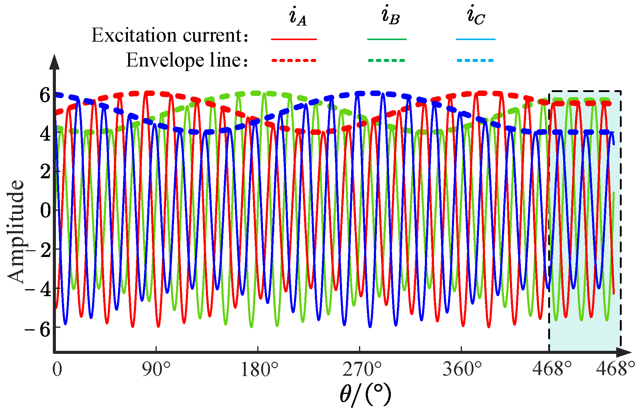
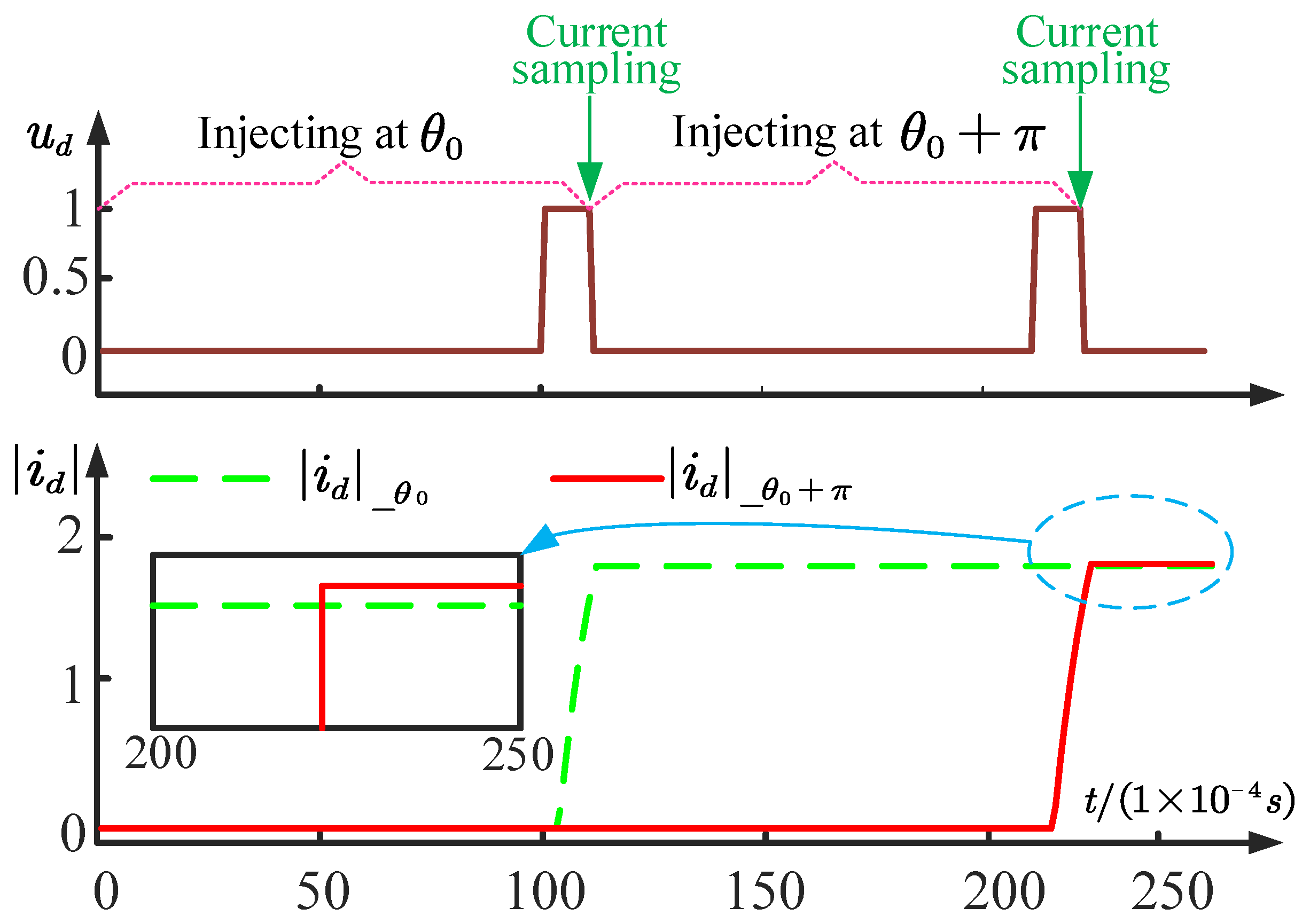
3.1. The Rotor Position Identification of Zero Speed

A simple approach based on high-frequency rotational voltage injection for initial rotor position detection (IPD) is adopted, which enables the motor to start with load at any position and avoids rotor motion. When the motor is stationary, a high-frequency signal such as that from Equation (15) is injected into the α β frame. Then, the effective value of the three-phase high-frequency excitation current is adopted to calculate the rotor position.
u α h s u β h s = V h s cos w h s t sin w h s t
In Equation (15), V h s and w h s are defined as the amplitude and frequency of the rotationally injected signal, respectively. u α / β h s represent the high-frequency sinusoidal voltage on the two-phase stationary coordinate system. On this basis, the half-differential inductance and the average inductance are introduced to reconstruct the high-frequency current response equation, as shown in Equation (16).
i α h s i β h s = V h s w h L 0 2 L 1 2 L 0 sin w h s t L 1 sin w h s t 2 θ L 0 cos w h s t + L 1 cos w h s t 2 θ
where i α / β h s represent the response current excited by u α / β h s . L 0 and L 1 are defined in Equation (17). θ is the rotor position when the motor is stationary.
L 0 = L d + L q 2 L 1 = L q L d 2
According to Equation (17), the high-frequency response current can be derived from the three-phase stationary coordination ( i A , i B , and i C ), as shown in Equation (18).
i A i B i C = V h s w h L 0 2 L 1 2 L 0 sin w h s t L 1 sin w h s t 2 θ L 0 sin w h s t 2 π / 3 L 1 sin w h s t 2 θ + 2 π / 3 L 0 sin w h s t + 2 π / 3 L 1 sin w h s t 2 θ 2 π / 3
From Equation (18), i A , i B , and i C are still sinusoidal AC signals, which means that θ can affect the amplitude of the three-phase current. When the motor parameters and injection frequency are determined, θ can modulate the three-phase current, as shown in Figure 5. Here, i A , i B , and i C can exhibit different effective values or amplitudes when the rotor is stationary at a certain angle. The rotor position is solved by a linear approximation method, and the result is shown in Equation (19), where I A r m s , I B r m s and I C r m s represent the effective value of i A , i B , and i C , respectively. Usually, the acquisition of the effective value is more accurate than the amplitude, which reduces the identification error caused by the sampling process. Here, the error of linear estimation is expressed in Equation (20) (calculated by 0 ° < θ 30 ° ).
θ = I C r m s I B r m s I A r m s I B r m s × 30 ° , 0 ° < θ 30 ° θ = I C r m s I A r m s I C r m s I B r m s × 30 ° + 30 ° , 30 ° < θ 60 ° θ = I B r m s I A r m s I C r m s I A r m s × 30 ° + 60 ° , 60 ° < θ 90 ° θ = I B r m s I C r m s I B r m s I A r m s × 30 ° + 90 ° , 90 ° < θ 120 ° θ = I A r m s I C r m s I B r m s I C r m s × 30 ° + 120 ° , 120 ° < θ 150 ° θ = I A r m s I B r m s I A r m s I C r m s × 30 ° + 150 ° , 150 ° < θ 180 °
Δ θ = I C r m s I B r m s I A r m s I B r m s × 30 °
From Equations (18)–(20), it can be seen that the initial position identification method is not sensitive to the injection amplitude, frequency and motor parameters.
However, neither the square-wave injection nor the rotation injection mentioned above can effectively identify the NS poles of the rotor. On the one hand, the derivation process of Equations (7)–(9) is based on the premise of θ ˜ e 0 , which is established when θ ˜ e π / 2 , π & π , π / 2 . The rotation matrix from d ^ q ^ to d q frame needs to take the opposite number, which means that Equation (9) needs to be re-derived, as shown in Equation (21):
cos θ e sin θ e = L d h u d h d d t i α h i β h
where the conclusion that the difference between the identified angle and the actual angle is π can be confirmed. Therefore, the identification of the NS pole is indeed a necessary prerequisite for the square-wave HFI. On the other hand, although the method of rotor position identification based on rotational injection has low sensitivity to injection signals, the solution results cannot be accurately mapped to the positions of the N and S poles. Therefore, a reliable method of NS detection (NSD) should be proposed to ensure the reliability of signal injection. To realize simple and effective NSD, the saturated saliency of the rotor is fully exploited. Voltages are respectively applied to the positive and negative directions of the d-axis identified by the IPD, which saturates or weakens the d-axis’ magnetic circuit. The d-axis response current can be derived in Equation (22) and roughly depicted in Figure 6.
i d = 1 L d V h _ n s d t = V h _ n s L d T
In Equation (22), V h _ n s and T represent the amplitude and time of high-level injection, respectively. θ 0 is defined as the initially identified rotor position. The position of the rotor can be accurately expressed by detecting the excitation current injected twice, whose solution principle is shown in Equation (23):
θ = θ 0 , if i d _ θ 0 > i d _ θ 0 + π θ = θ 0 + π , if i d _ θ 0 < i d _ θ 0 + π
where i d _ θ 0 and i d _ θ 0 + π denote the response currents’ absolution excited by the voltage injected at positions θ 0 and θ 0 + π , respectively.
Through the above analysis and design, the rotor position detection scheme at zero speed is divided into three links, including IPD, NSD and square-wave HFI. In order to meet the accuracy of square-wave HFI at the start time, the square-wave HFI can be put into operation before the motor starts. The zero-speed rotor position detection can be described in Figure 7 by using stateflow.

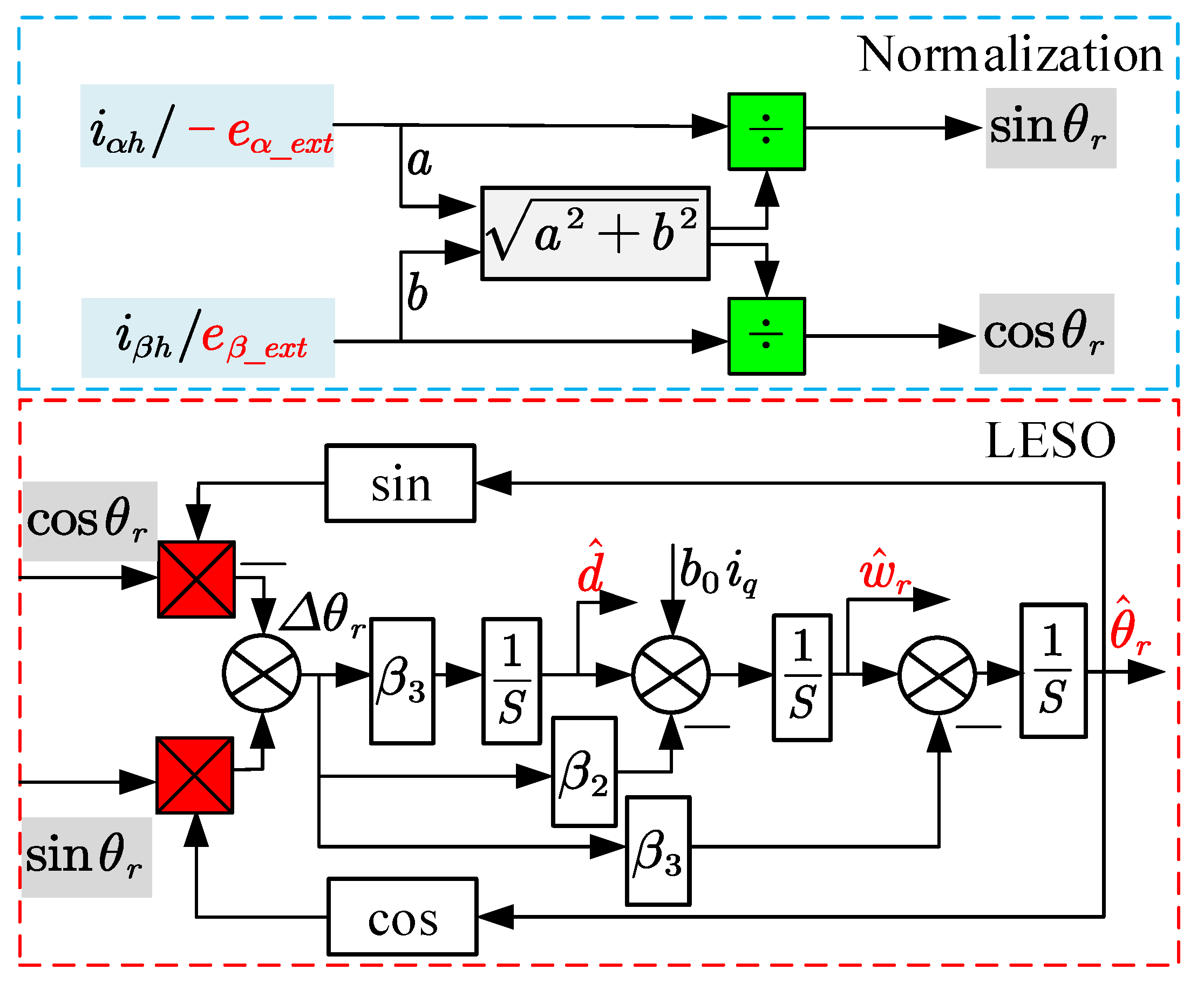
3.2. Calculation of Rotor Position and Speed in Low-Speed Range

In the low-speed range, both HFI and HSMO are activated. To obtain more accurate rotor position and speed information, an LESO is designed to solve the rotor information. The kinematic equation for the PMSM is re-derived in Equation (24):
w ˙ r = b 0 i q + d
In Equation (24), b 0 is defined as the characteristic gain coefficient. d represents the system disturbance. w ˙ r stands for the derivative of the angular velocity. Defining d as a new expansion variable, an LESO is established in Equation (25) to acquire rotor information.
Δ θ r = θ ^ r θ r θ ^ ˙ r = w ^ r β 1 Δ θ r w ^ ˙ r = b 0 i q + d ^ β 2 Δ θ r d ^ ˙ = β 3 Δ θ r
where β 1 , β 2 and β 3 denote the gain coefficients of LESO. d ^ , θ ^ r , and w ^ r represent disturbance, electrical angle, and electrical angular speed observations, respectively. The frequency domain equation of Equation (25) is re-derived in Equation (26) to analyze the observability.
s · θ ^ s = w ^ r s β 1 Δ θ r s s · w ^ r = b 0 i q s + d ^ s β 2 Δ θ r s s · d ^ = β 3 Δ θ r s
From Equation (26), the observer error transfer function can be expressed in Equation (27):
G s = s 3 s 3 + β 1 s 2 + β 2 s + β 3
Using multiple pole configurations, the gain coefficient can be adjusted according to Equation (28):
β 1 = 3 w 0 β 2 = w 0 2 β 3 = w 0 3
where the observation error can converge to 0 in time domain, which indicates that rotor information can be effectively observed.
In addition, in order to avoid the influence of magnitude from the EEMF and high-frequency response current, it is necessary to normalize the input signal of the LESO. Therefore, the block diagram of the normalized LESO can be designed in Figure 8.
From Figure 8, it is worth noting that Δ θ r is defined differently in the HSMO and HFI, as shown in Equation (29).
Δ θ r sin Δ θ r = e α cos θ ^ r e β sin θ ^ r e α 2 + e β 2 , for HSMO Δ θ r sin Δ θ r = i β h cos θ ^ r i α h sin θ ^ r i α h 2 + i β h 2 , for HFI

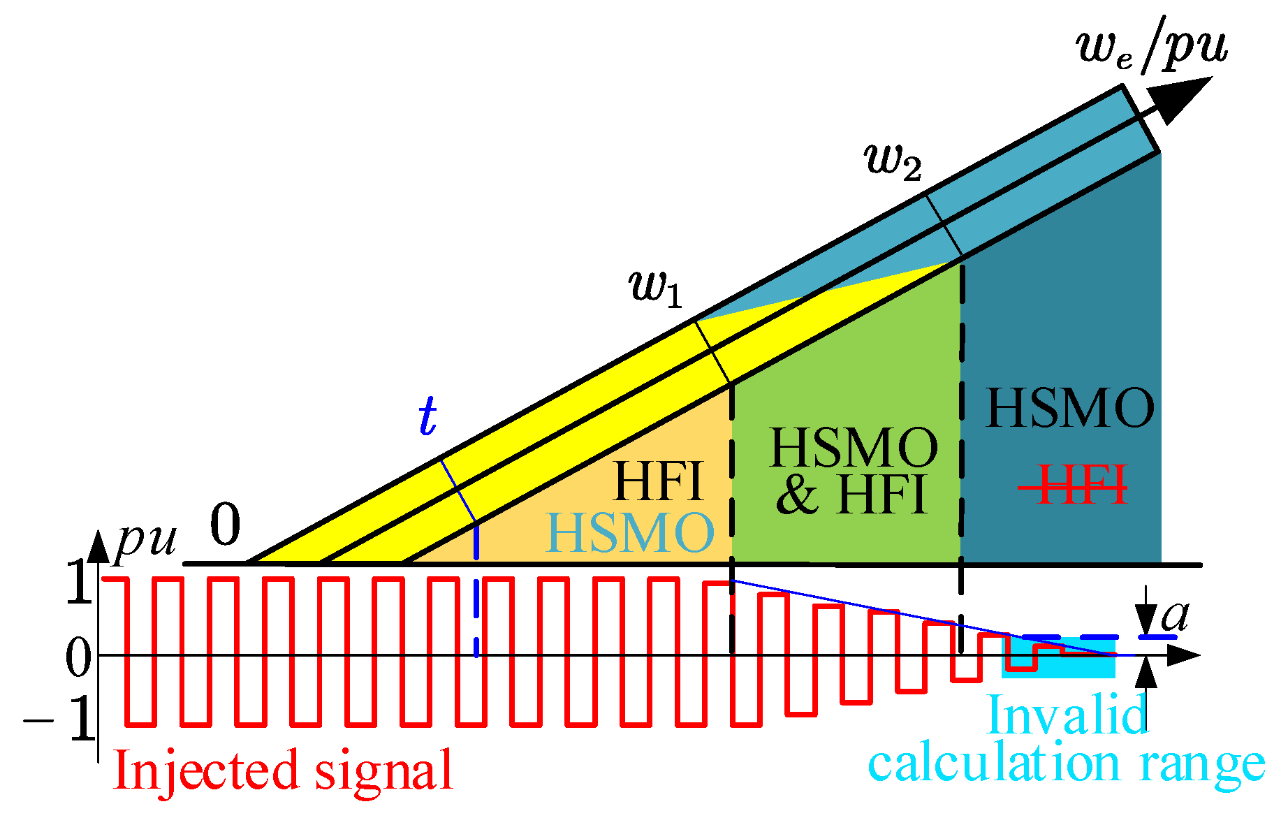
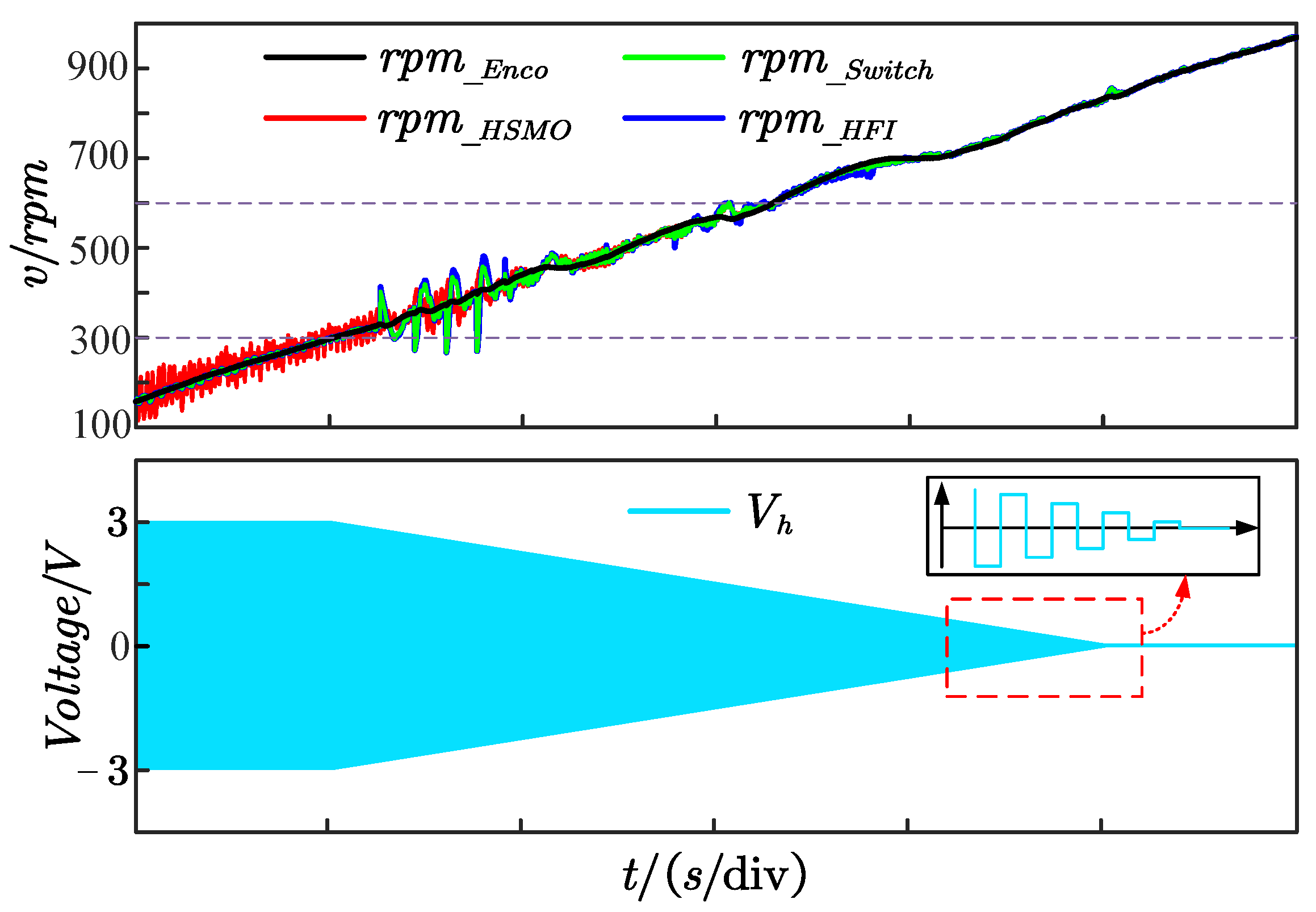
3.3. Smooth Transition Strategy in Medium-Speed Range

In order to achieve higher reliability at high speed and low speed, it is necessary to propose a smooth transition strategy to avoid the vibration of PMSM speed and torque. Therefore, a linearly weighted observer switching strategy is proposed in the medium-speed phase. Then, in order to further suppress the jitter caused by the exit of the injected signal, an exit mode in which the injected signal is linearly attenuated is added to the linearly weighted switching strategy, and its switching principle is shown in Figure 9.
According to Figure 9, a time limit is introduced into the switching control part to avoid switching logic errors caused by the non-convergent state. The linearly weighted switching logic can be expressed in Equation (30):
if t < t 0 w e = w e _ H F I , θ e = θ e _ H F I ; else if w e _ H F I < = w 1 | | w e _ H S M O < = w 1 w e = w e _ H F I , θ e = θ e _ H F I ; else if w e _ H F I > w 1 & w e _ H S M O > w 1 & w e _ H F I < w 2 & w e _ H S M O < w 2 M = w 2 w e _ H S M O / w 2 w 1 w e = w e _ H F I M + w e _ H S M O 1 M θ e = θ e _ H F I M + θ e _ H S M O 1 M ; else w e = w e _ H S M O , θ e = θ e _ H S M O
From Equation (30), once the motor enters the medium-speed stage, the linear attenuation function of the injected signal is triggered, which means the amplitude of the injected signal can decrease with a certain slope k. Here, it is necessary to set a threshold a to avoid a situation where the amplitude of the injected signal is too small to effectively solve the rotor signal. In this way, smooth switching can be achieved, and the jitter caused by exiting the injection signal can be reduced.

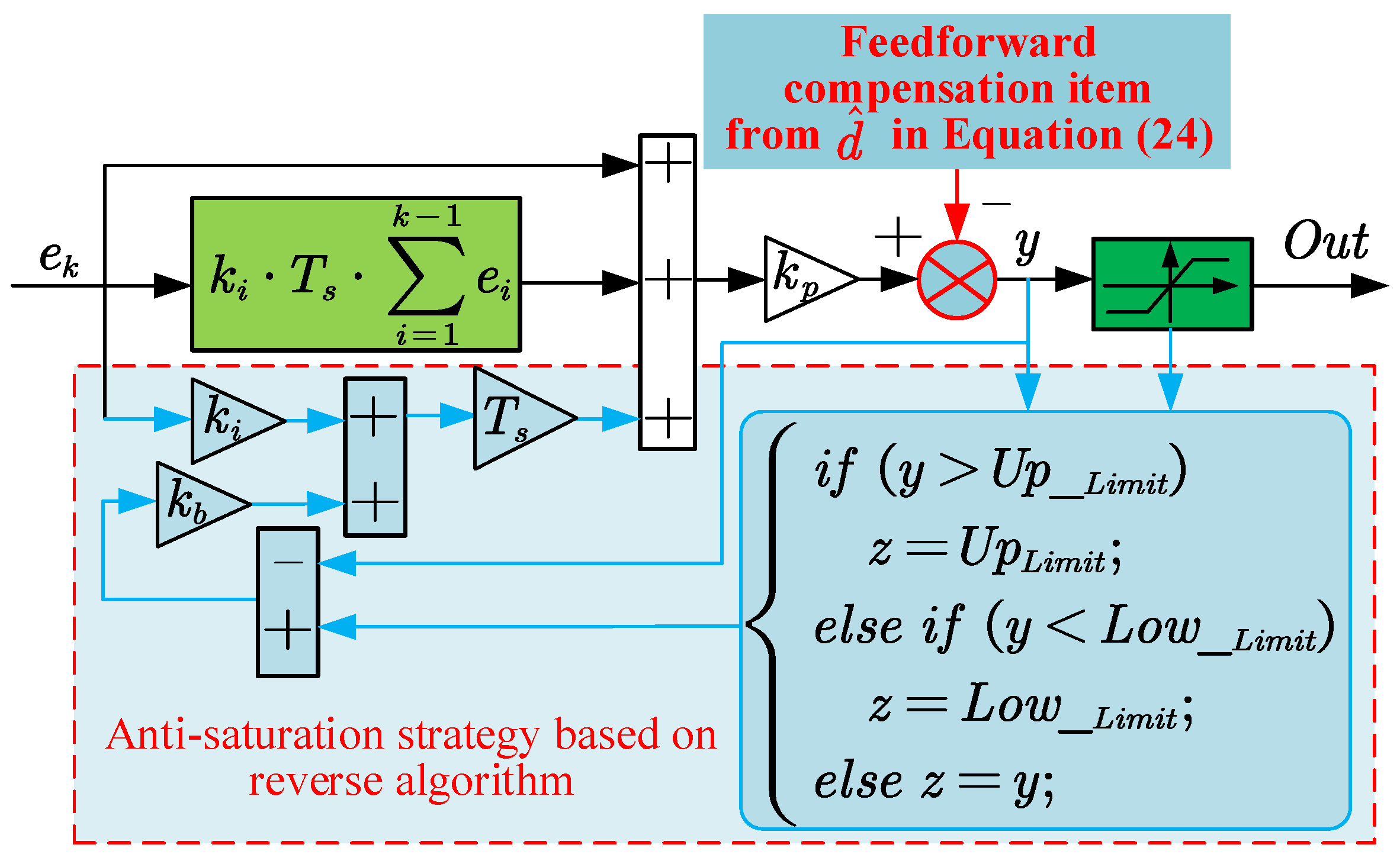
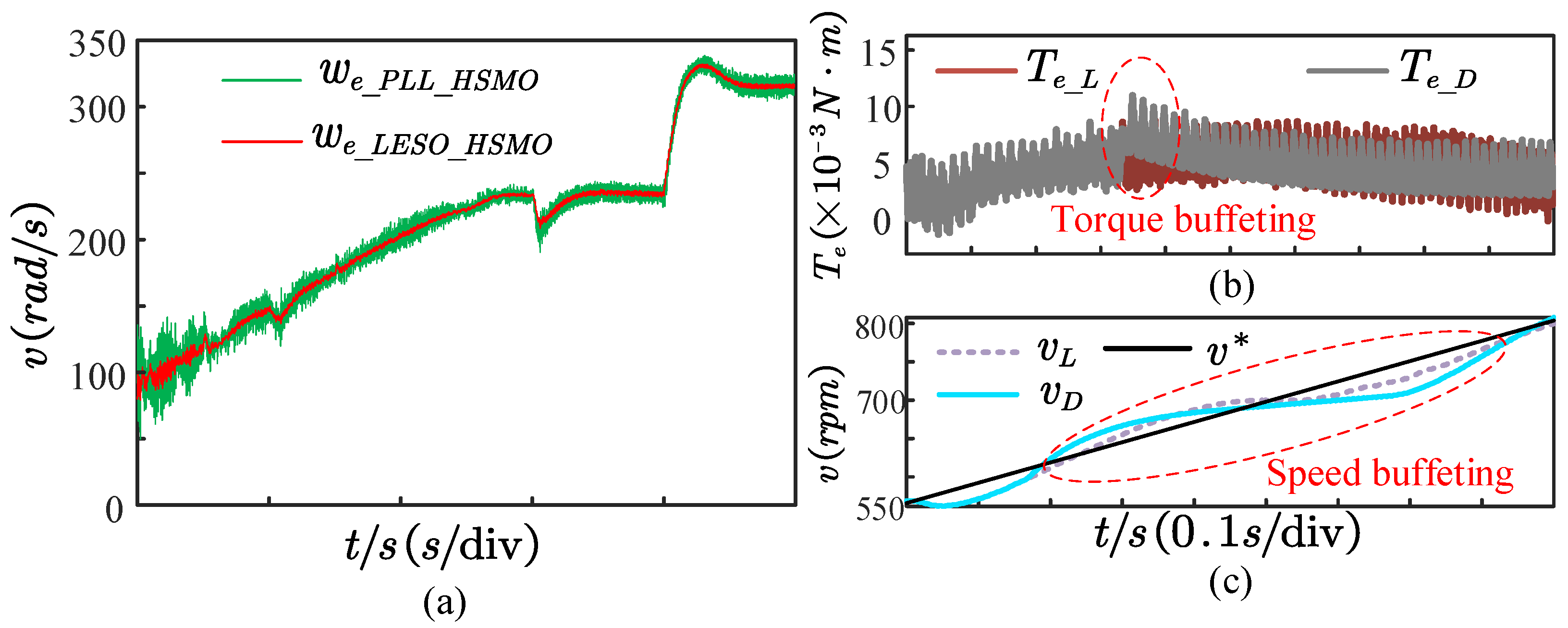
3.4. Optimization of System Anti-Disturbance Performance in High-Speed Range

Based on disturbance observations, a new PI controller with disturbance compensation and an anti-saturation link is designed for speed control, which is named PI plus in this paper. On the one hand, the disturbance term observed by the LESO is compensated for the speed controller, which can effectively improve the anti-disturbance performance of the system. However, in order to avoid the interference caused by the injected signal in the low- and medium-speed range, it would be a reasonable choice to compensate disturbance only in the high-speed range. On the other hand, an anti-windup strategy based on inverse control is proposed to avoid the integral windup phenomenon of the PI controller. Combining the above two optimization directions, the PI plus controller designed is shown in Figure 10.
In Figure 10, k p , k i and k b represent proportional, integral and anti-saturation coefficients, respectively. e k , k and T s are defined as input error, calculation time and calculation period, respectively. U p _ L i m i t and L o w _ L i m i t are the upper and lower limits of the controller output, which are limited by MCU and hardware parameters. Furthermore, the above anti-saturation algorithm can also be configured into the current loop.
Based on the above derivation and design, the block diagram of the full-speed sensorless control system for the PMSM is established in Figure 11. Here, the parts, including the current loop, SVPWM algorithm, rotor information identification, observer switching algorithm and sampling, are executed at a frequency of 10 kHz. To make the best use of the MCU’s computing resources, the speed loop is implemented at a frequency of 200 Hz.
From Figure 11, a parameter tuning scheme for a dual-loop controller is proposed. Among them, “ i ” is the expected value of “i”. The closed-loop transfer function of the current loop can be derived in Equation (31) from Equation (3).
G c l o s e _ d q i s = P I s G d q i s 1 + P I s G d q i s = s / k i + 1 L s 2 / k p i k i i + k p i + R / i i + 1
In Equation (31), k p i and k i i are the proportional-integral coefficients of the PI controller. It should be noted that Equation (31) can only be established in series PI. By adopting pole zero cancellation, the system can be reduced to a first-order system, which is equivalent to a first-order low pass filter (LPF). The current loop bandwidth ( B a n d ) is introduced according to the cutoff frequency. Therefore, the PI parameters for current loop can be derived in Equation (32).
k p i = 2 π L · B a n d k i i = R / L
From G c l o s e _ d q i ( s ) , the speed loop open-loop transfer function is further derived in Equation (33):
G o p e n w = k p w p n k i w + s J s 2 1 + L s / k p i
According to the phase and amplitude constraints, the parameters of the speed loop controller are designed in Equation (34):
k p w = 2 π J · B a n d / δ · p n k i w = 2 π · B a n d / δ 2
where J and p n represent the moment of inertia and the number of pole pairs of the rotor, respectively. δ is defined as the damping coefficient, which determines the speed loop phase margin. Therefore, the parameters of the dual-loop controller can be realized by setting B a n d and δ .

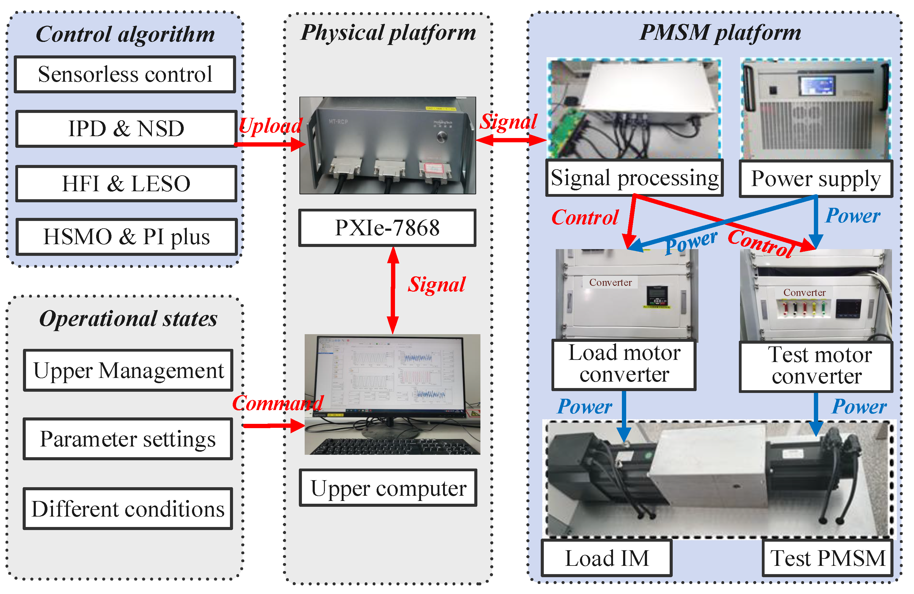
4. Experimental Verification

Based on the above design, the control algorithm is deployed to the platform shown in Figure 12. This platform employs the StarSim RCP as a controller developed by ARM and FPGA, which supports a maximum 1 MHz analog sampling and digital output. The controller is also equipped with corresponding host computer and monitoring software, which can achieve a sampling rate of 10 kHz. Moreover, the platform is equipped with an induction motor as a dynamic load, which is driven by an inverter that supports a switching frequency of up to 20 kHz. In addition, the data processing module is applied to demodulate the encoder signal of the motor and isolate each signal. The zero-speed rotor information identification, medium-speed observer switching and high-speed load performance are tested, respectively. The motor and various control parameters are shown in Table 2. Among them, I m a x and V m a x represent the speed loop and current loop output limits, respectively. w 0 H F I and w 0 H S M O are respectively defined as the bandwidth of the LESO in the process of solving the HFI and HSMO rotor information. G H S M O and K H S M O are the control parameters of the HSMO.

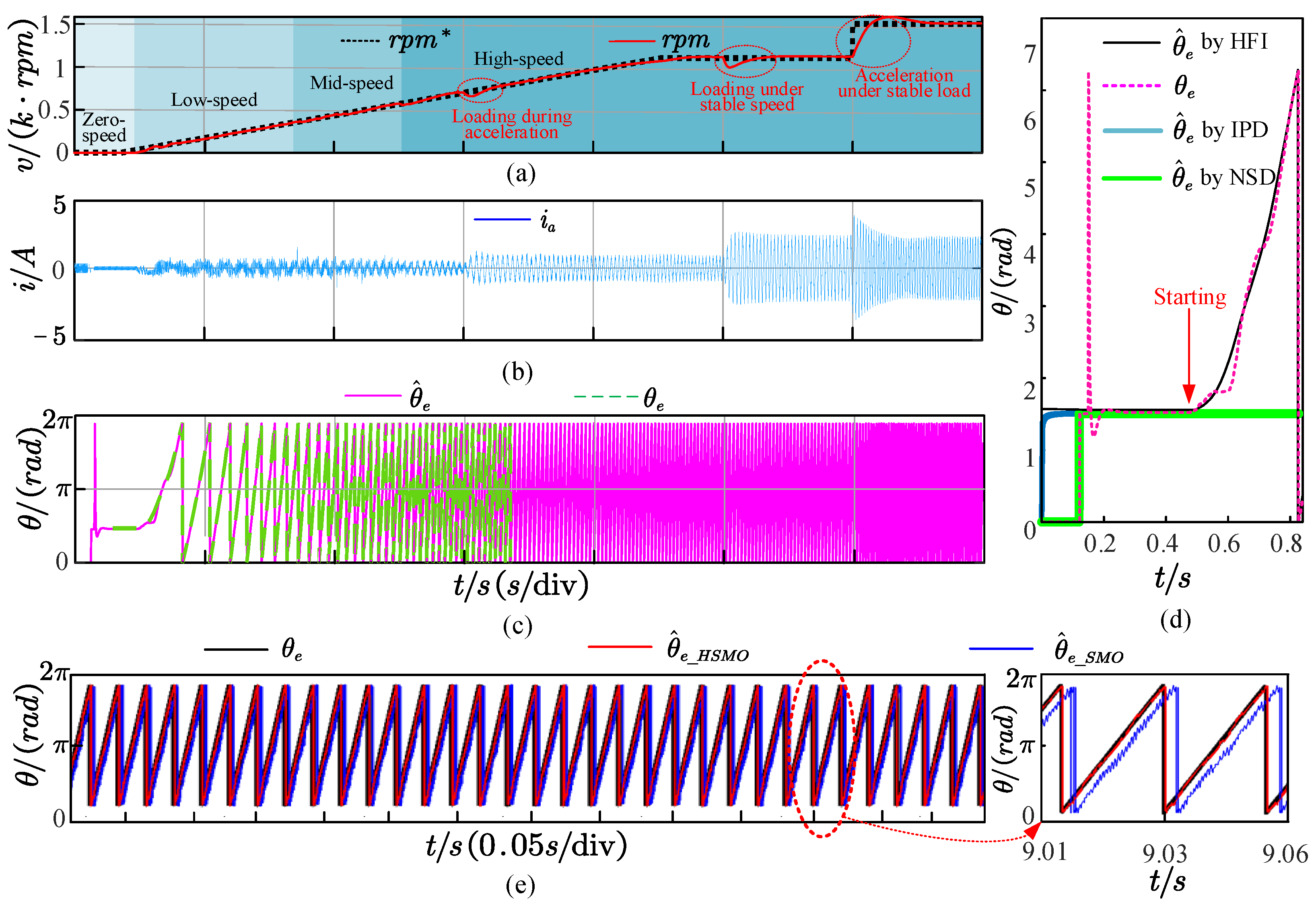
4.1. Speed Response Test in Full-Speed Threshold

Defining the medium-speed threshold range as 0.2–0.4 pu, on-load experiments are performed to demonstrate the performance of the senseless control strategy when the reference speed is given at 0–1500 rpm. The speed–response curve in the full-speed range is shown in Figure 13a.
In Figure 13a,b, the control performance of the proposed sensorless strategy in the full-speed threshold is verified under the cases of fixed load, variable load and speed. From Figure 13c, it is worth noting that the HSMO effectively avoids the phase delay compared with the traditional SMO. Furthermore, Figure 13d reveals that the IPD process can accurately identify the initial position of the rotor when it is positioned at 45°. On this basis, the NSD strategy can precisely detect the polarity of the rotor, which further ensures that the HFI strategy can properly provide the rotor information to achieve a stable speed change response during startup. Finally, Figure 13e presents a comparison between an HSMO and a conventional SMO in terms of rotor angle estimation results. Here, the function of “arctan” is employed for angle calculation. And r p m represents the expected value of speed. The results reveal that a conventional SMO introduces significant phase lag and severe oscillation phenomena. In comparison, an HSMO can effectively suppresses both oscillation and phase lag phenomena.
In addition, Figure 14 further shows the speed–response curve and the injection signal withdrawal process under the observer switching scheme based on linear weighting. Here, r p m _ E n c o , r p m _ H F I , r p m _ H S M O and r p m _ S w i t c h represent the electrical speed from the encoder, HFI, HSMO and linear weighting, respectively. Above all, Figure 14 indicates that smooth switching between observers is achieved with linear weighting. Meanwhile, the identification performance cannot be affected during the linear exit of the injected signal. Most of all, the jitter is generally eliminated by the filtering function as it enters the medium-speed domain, which results in a smoother actual speed r p m _ E n c o .
Finally, the effects of LESO, the linear weighted switching strategy and the injection signal linear exit scheme are verified in Figure 15. Here, v is denoted as expected value. It proves that the LESO has better identification capability than the PLL under the same observer bandwidth. Even when the motor is in a steady state, the LESO can reduce at least 50% of the chattering amplitude. Moreover, Figure 15b,c compares the torque and speed response performance under the linear exit and direct exit modes of the injected signal, respectively. The experiments where the injected signal exits directly and linearly are further performed; their results are shown in Figure 15b,c. Note that the way in which the injected signal exits directly creates spikes in torque jitter that cause larger fluctuations. In contrast, the way that the injected signal exits linearly can suppress torque chattering peak and speed fluctuation, which further improves system stability.

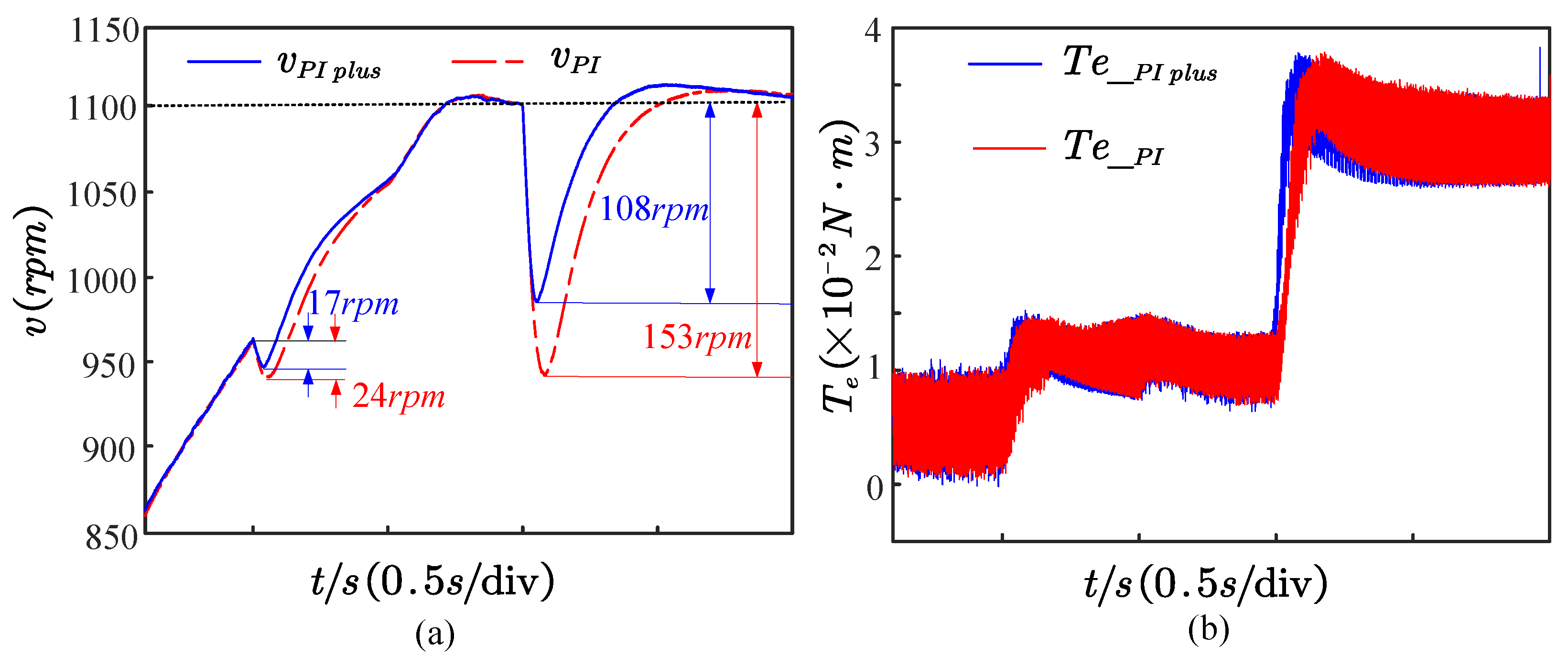
4.2. Anti-Load Disturbance Performance Test at High-Speed Threshold

In order to further verify the performance of the PI plus speed controller, a comparative experiment on resistance to load disturbance is performed, and its corresponding results are shown in Figure 16. Here, a constant load with 0.01 N · m is applied to the motor during uniform acceleration. From Figure 16a, it is clear that the speed drop is reduced by approximately 7 rpm compared with the traditional PI. Therefore, the PI plus controller can effectively reduce the speed drop by comparing it with the PI control with consistent load disturbance.
Likewise, a load with 0.02 N · m is further applied in the constant velocity section. The test results show that the speed drop can be effectively reduced by about 45 rpm. Furthermore, Figure 16b also reveals that the system using the PI plus controller can make a faster torque response to improve the disturbance immunity of the system.
For another, the parameters of the PMSM are often not strictly accurate during the operation. Therefore, parameter perturbation experiments based on the sensorless control system of the HSMO are performed. By considering the sensitivity of the flux linkage ( ψ f ) to temperature, the simulation test of the disturbance ( ± 0.3 ψ f ) is carried out at a rated speed, whose results are shown in Figure 17.
In Figure 17, the system using the HSMO can converge to the actual value within 2 s. Correspondingly, the maximum speed change is only 0.073 pu under the disturbance of 0.3 ψ f . During the whole parameter perturbation test process, the system can effectively converge to the expected value. Therefore, it is worthy of affirmation that the observer can have strong anti-parameter disturbance performance under the rated operating condition. Generally, the adoption of a PI plus controller and an HSMO has a practical effect on improving the dynamic performance of a sensorless control system for a PMSM.

5. Conclusions

This paper designs a sensorless control system for a PMSM based on a square-wave HFI and HSMO in full-speed threshold. From experiments, it has been demonstrated that the proposed sensorless control system can start up with a load in arbitrary positions. Simultaneously, this system maintains stable performance for variable speed and load.
The primary conclusions of this paper are summarized below.
  • In the aspect of rotor information estimation, an LESO is devised for rotor state observation and disturbance estimation. Experimental results demonstrate that LESO yields superior rotor speed identification performance compared to traditional PLL.
  • At medium speed, a linear exit scheme based on an injection signal is designed, building upon linear weighted switching for observers. Experimental results prove that the proposed switching strategy can effectively suppress speed jitter.
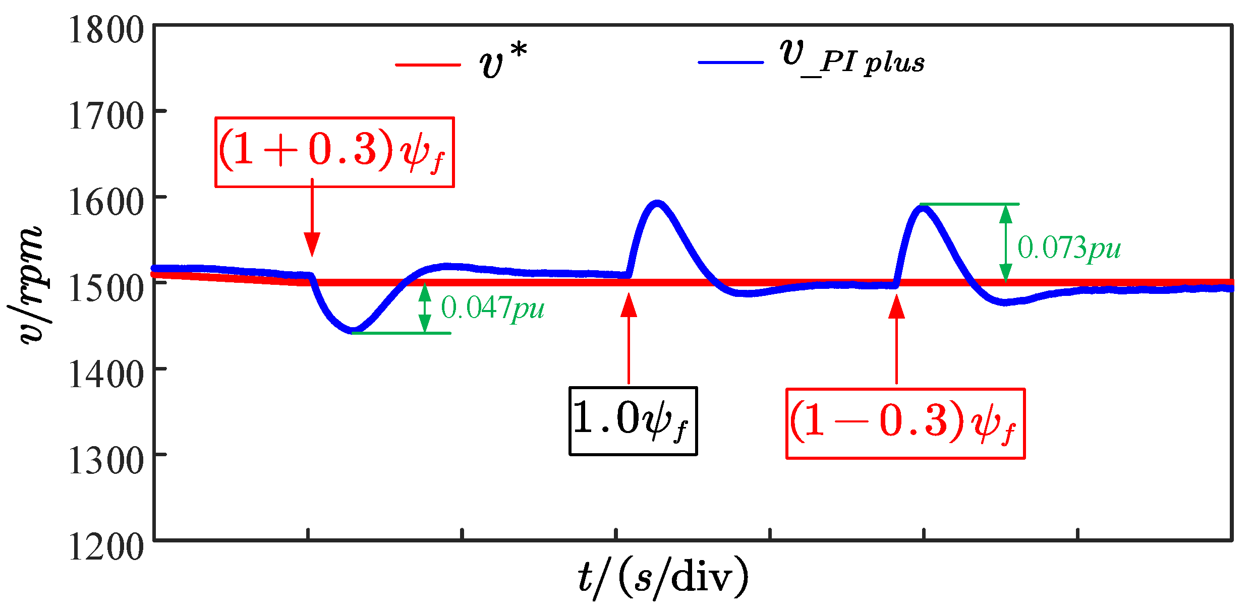
  • During high speed, the robustness and disturbance rejection performance of the proposed sensorless estimation algorithm and designed controller are discussed, respectively. Parameter perturbation experiments show that the system only produces 0.047 pu and 0.073 pu speed fluctuations when ψ f is disturbed with ±0.3 pu, respectively. Load disturbance experiments indicate that the proposed speed controller can be reduced by 45 rpm for speed fluctuations with a load of 0.02 N · m in comparison to a PI. Simultaneously, it achieves a faster torque response. In conclusion, the proposed sensorless control system is capable of achieving a seamless transition process, along with excellent robustness and disturbance rejection performance throughout the entire operational range.

Author Contributions

Y.H. wrote this article, designed the control method, implemented the hardware platform, drew the figures, and performed the simulation and the experiment. M.Z. supervised the study, coordinated the investigations, and checked the manuscript’s logical structure. Y.W. validated the simulation and hardware experimental data. H.Z. reviewed the writing and editing. M.L. provided practical suggestions and evaluated the feasibility of the application. All authors have read and agreed to the published version of the manuscript.

Funding

This work was supported in part by the Natural Science Foundation of China under Grant 61563045, and in part by the International Cooperation Projects of Shihezi University under Grant GJHZ202003, in part by the key Laboratory of Northwest Agricultural Equipment, Ministry of Agriculture and Rural Affair, and in part by Xinjiang Production and Construction Corps Key Laboratory of Modern Agricultural Machinery.

Institutional Review Board Statement

Not applicable.

Informed Consent Statement

Not applicable.

Data Availability Statement

Not applicable.

Acknowledgments

We sincerely thank Shanghai Yuankuaz Energy Technology Co., Ltd. for providing technical guidance for the use of the hardware experimental platform.

Conflicts of Interest

The authors declare no conflict of interest.

Abbreviations

The following abbreviations are used in this manuscript:
PMSMPermanent Magnet Synchronous Motor
IPMSMInterior Permanent Magnet Synchronous Motor
SPMSMSurface Permanent Magnet Synchronous Motor
SMOSliding Mode Observer
HSMOHigher order Sliding Mode Observer
HFIHigh Frequency signal Injection
LESOLinear Extended State Observer
EKFExtended Kalman Filter
LPFLow Pass Filter
back EMFback ElectroMotive Force
IPDInitial Position Detection
NSDNS Detection

References

  1. Wang, G.; Valla, M.; Solsona, J. Position Sensorless Permanent Magnet Synchronous Machine Drives—A Review. IEEE Trans. Ind. Electron. 2020, 67, 5830–5842. [Google Scholar] [CrossRef]
  2. Khanh, P.Q.; Anh, H.P.H. Novel Sensorless PMSM Speed Control Using Advanced Fuzzy MRAS Algorithm. Arab. J. Sci. Eng. 2022, 47, 14531–14542. [Google Scholar] [CrossRef]
  3. Varatharajan, A.; Pellegrino, G.; Armando, E.; Hinkkanen, M. Sensorless Synchronous Motor Drives: A Review of Flux Observer-Based Position Estimation Schemes Using the Projection Vector Framework. IEEE Trans. Power Electron. 2021, 36, 8171–8180. [Google Scholar] [CrossRef]
  4. Hwang, C.-E.; Lee, Y.; Sul, S.K. Analysis on Position Estimation Error in Position-Sensorless Operation of IPMSM Using Pulsating Square Wave Signal Injection. IEEE Trans. Power Electron. 2019, 55, 458–470. [Google Scholar] [CrossRef]
  5. Bao, D.; Wu, H.; Wang, R.; Zhao, F.; Pan, X. Full-Order Sliding Mode Observer Based on Synchronous Frequency Tracking Filter for High-Speed Interior PMSM Sensorless Drives. Energies 2020, 13, 6511. [Google Scholar] [CrossRef]
  6. Shahzad, K.; Jawad, M.; Ali, K.; Akhtar, J.; Khosa, I.; Bajaj, M.; Elattar, E.E.; Kamel, S. A Hybrid Approach for an Efficient Estimation and Control of Permanent Magnet Synchronous Motor with Fast Dynamics and Practically Unavailable Measurements. Appl. Sci. 2022, 12, 4958. [Google Scholar] [CrossRef]
  7. Zhu, Y.; Tao, B.; Xiao, M.; Yang, G.; Zhang, X.; Lu, K. Luenberger Position Observer Based on Deadbeat-Current Predictive Control for Sensorless PMSM. Electronics 2020, 9, 1325. [Google Scholar] [CrossRef]
  8. Mai, Z.; Xiao, F.; Fu, K.; Liu, J.; Lian, C.; Li, K.; Zhang, W. HF Pulsating Carrier Voltage Injection Method Based on Improved Position Error Signal Extraction Strategy for PMSM Position Sensorless Control. IEEE Trans. Power Electron. 2021, 36, 9348–9360. [Google Scholar] [CrossRef]
  9. Wang, H.; Wang, J.; Xu, W. A High Precision Initial Position Estimation Method for Low Saliency Ratio Machine Based on Image Tracking. IEEE Trans. Power Electron. 2023, 1–13. [Google Scholar] [CrossRef]
  10. Yeh, H.-C.; Yang, S.-M. Phase Inductance and Rotor Position Estimation for Sensorless Permanent Magnet Synchronous Machine Drives at Standstill. IEEE Access 2021, 9, 32897–32907. [Google Scholar] [CrossRef]
  11. Li, T.; Wang, Z.; Li, M.; Wang, D.; Kong, H. A Whole Speed Range Sensorless Method for SPMSM Drive. In Proceedings of the 2022 China Automation Congress (CAC), Xiamen, China, 25–27 November 2022; pp. 1549–1553. [Google Scholar] [CrossRef]
  12. Zhang, Z. Sensorless Back EMF Based Control of Synchronous PM and Reluctance Motor Drives—A Review. IEEE Trans. Power Electron. 2022, 37, 10290–10305. [Google Scholar] [CrossRef]
  13. Zhang, X.; Li, H.; Yang, S.; Ma, M. Improv. Improved Initial Rotor Position Estimation for PMSM Drives Based on HF Pulsating Voltage Signal Injection. IEEE Trans. Ind. Electron. 2018, 65, 4702–4713. [Google Scholar] [CrossRef]
  14. Nair, S.V.; Hatua, K.; Durga Prasad, N.V.P.R.; Reddy, D.K. Quick and Seamless Transition Method for I-f to Sensorless Vector Control Changeover and on-the-fly Start of PMSM Drives. IET Electr. Power Appl. 2020, 14, 2231–2242. [Google Scholar] [CrossRef]
  15. Vidlak, M.; Makys, P.; Gorel, L. A Novel Constant Power Factor Loop for Stable V/f Control of PMSM in Comparison against Sensorless FOC with Luenberger-Type Back-EMF Observer Verified by Experiments. Appl. Sci. 2022, 12, 9179. [Google Scholar] [CrossRef]
  16. Yousefi-Talouki, A.; Pescetto, P.; Pellegrino, G.; Boldea, I. Combined Active Flux and High-Frequency Injection Methods for Sensorless Direct-Flux Vector Control of Synchronous Reluctance Machines. IEEE Trans. Power Electron. 2017, 33, 2447–2457. [Google Scholar] [CrossRef]
  17. Liu, J.; Chen, J. A Changeover of Rotor Position Estimation between Rotor Speed Adaptive Stator Flux Observer and High-frequency Injection and Dead-Time Compensation Scheme for Sensorless Vector Control System of PMSM. In Proceedings of the 2019 22nd International Conference on Electrical Machines and Systems (ICEMS), Harbin, China, 11–14 August 2019; pp. 1–6. [Google Scholar] [CrossRef]
  18. Ding, H.; Zou, X.; Li, J. Sensorless Control Strategy of Permanent Magnet Synchronous Motor Based on Fuzzy Sliding Mode Observer. IEEE Access 2022, 10, 36743–36752. [Google Scholar] [CrossRef]
  19. Bist, A.; Jadhav, S. Sensorless Control based on Sliding Mode Observer for PMSM drive. In Proceedings of the 2020 IEEE International Conference on Power Electronics, Drives and Energy Systems (PEDES), Jaipur, India, 16–19 December 2020; pp. 1–6. [Google Scholar] [CrossRef]
  20. Dendouga, A. Conventional and Second Order Sliding Mode Control of Permanent Magnet Synchronous Motor Fed by Direct Matrix Converter: Comparative Study. Energies 2020, 13, 5093. [Google Scholar] [CrossRef]
  21. Zhan, Y.; Guan, J.; Zhao, Y. An adaptive second-order sliding-mode observer for permanent magnet synchronous motor with an improved phase-locked loop structure considering speed reverse. Trans. Inst. Meas. Control 2020, 42, 1008–1021. [Google Scholar] [CrossRef]
  22. Wu, T.; Luo, D.; Wu, X.; Liu, K.; Huang, S.; Peng, X. Square-Wave Voltage Injection Based PMSM Sensorless Control Considering Time Delay at Low Switching Frequency. IEEE Trans. Ind. Electron. 2021, 69, 5525–5535. [Google Scholar] [CrossRef]
  23. Wu, C.; Chen, Z.; Chen, Q. Hybrid-Modulation-Based Full-Speed Sensorless Control for Permanent Magnet Synchronous Motors. IEEE Trans. Power Electron. 2022, 37, 5908–5917. [Google Scholar] [CrossRef]
  24. Ning, B.; Zhao, Y.; Cheng, S. An Improved Sensorless Hybrid Control Method of Permanent Magnet Synchronous Motor Based on I/F Startup. Sensors 2023, 23, 635. [Google Scholar] [CrossRef] [PubMed]
  25. Cui, W.; Zhang, S.; Feng, Y. Improved sensorless control scheme for PMSM based on high-frequency square-wave voltage injection considering non-linear change of inductance in D-Q axis. AIP Adv. 2021, 11, 015121. [Google Scholar] [CrossRef]
  26. Liu, L.; Jin, D.; Si, J.; Liang, D. A Novel Nonsingular Fast Terminal Sliding Mode Observer Combining I-F Method for Wide-Speed Sensorless Control of PMSM Drives. IET Power Electron. 2023, 16, 843–855. [Google Scholar] [CrossRef]
  27. Hou, Q.; Ding, S.; Yu, X. Composite Super-Twisting Sliding Mode Control Design for PMSM Speed Regulation Problem Based on a Novel Disturbance Observer. IEEE Trans. Energy Convers. 2021, 36, 2591–2599. [Google Scholar] [CrossRef]
Figure 1. The response curve of current during square wave injection.
Electronics 12 03759 g001
Figure 2. The high frequency response current and its envelope.
Electronics 12 03759 g002
Figure 3. The block diagram of HSMO.
Electronics 12 03759 g003
Figure 4. The main tasks and purposes of the four speed domains.
Electronics 12 03759 g004
Figure 5. The schematic diagram of the modulation effect of θ on the three-phase excitation current.
Electronics 12 03759 g005
Figure 6. The injection voltage and response current curves during NSD.
Electronics 12 03759 g006
Figure 7. A schematic diagram of state machine in zero-speed rotor position identification.
Electronics 12 03759 g007
Figure 8. The block diagram of normalized LESO.
Electronics 12 03759 g008
Figure 9. A schematic diagram of a linearly weighted switching strategy with linear attenuation of the injected signal.
Electronics 12 03759 g009
Figure 10. The controller block diagram of PI plus for speed loop.
Electronics 12 03759 g010
Figure 11. The block diagram of sensorless control system for PMSM in full-speed domain.
Electronics 12 03759 g011
Figure 12. The experiment platform.
Electronics 12 03759 g012
Figure 13. The response curve in full-speed domain. (a) Speed following curve; (b) response curve of i a ; (c) angle observation curve; (d) position identification result in zero speed; (e) position identification result from encoder, HSMO and SMO.
Electronics 12 03759 g013
Figure 14. The process of linear switching of rotational speed and linear exit of injection signal under the medium-speed threshold.
Electronics 12 03759 g014
Figure 15. (a) Speed solution results based on PI and LESO; (b) torque–response curves of injection signal linear exit and direct exit; (c) speed–response curves of injected signal linear exit and direct exit.
Electronics 12 03759 g015
Figure 16. The speed– and torque–response curves in PI and PI plus. (a) Speed curve; (b) Torque curve.
Electronics 12 03759 g016
Figure 17. The results of the parameter ( ψ f ) disturbance test at rated speed.
Electronics 12 03759 g017
Table 1. Sensorless control schemes for PMSM.
RefsContributionsLimitations
Bao D. (2020) [5]Proposed a full-order SMO to inhibit harmonic influence of inverter nonlinearity1. Low speed is unreliable. 2. Zero speed is not convergent for PMSM.
Shahzad K. (2022) [6]Proposed a sensorless control scheme combining MPC and EKF1. The calculation is complex. 2. The computing power of MCU is high.
Zhu Y. (2020) [7]Proposed a sensorless control scheme by combining Luenberger observer and deadbeat-current predictive control1. The observer is sensitive to model parameters. 2. The reliability of rotor information identification is affected by signal-to-noise ratio.
Z. Mai (2021) [8]An improved position error signal extraction strategy based on amplitude observer was designed on the basis of pulse vibration high-frequency injection1. The identification accuracy is affected by the nonlinearity of the inverter. 2. LPF brings phase lag.
H. Wang (2023) [9]Proposed an estimation method for rotor position using image tracking and HFILarge amount of calculation and high hardware cost
H.-C. Yeh [10]Line-to-line voltage injection and q d voltage injection for IPDIt is better to consider extending the application speed threshold
T. Li (2022) [11]A hybrid observer model and a linear weighted switching method were proposedChattering caused by injected signals and SMO deserves further attention
Our workA hybrid observer model, a linear weighted switching method, a linear exit scheme for the injected signal, disturbance compensationThis scheme deserves further study
Table 2. Main motor and control parameters.
ParametersValuesParametersValuesParametersValues
R s 0.405 Ω L d 0.45 mH L q 0.4 mH
ψ f 0.00529  V · s p n 2J × 10 4   kg · m 2
B0.0001  N · m · s n N 1500 rpm B a n d 400
δ 70 V m a x 8 I m a x 13.8
w 0 H F I 90 w 0 H S M O 70 G H S M O 0.35
b 0 615 w f _ L P F 500 Hz t I P D 0.1 s
t N S D 0.05 s t N S _ H / t N S _ L 0.001 s f P W M 10 kHz
Disclaimer/Publisher’s Note: The statements, opinions and data contained in all publications are solely those of the individual author(s) and contributor(s) and not of MDPI and/or the editor(s). MDPI and/or the editor(s) disclaim responsibility for any injury to people or property resulting from any ideas, methods, instructions or products referred to in the content.

