Article

A Software-Defined Distributed Architecture for Controlling Unmanned Swarm Systems

1
China North Artificial Intelligence & Innovation Research Institute, Beijing 100072, China
2
Collective Intelligence & Collaboration Laboratory, Beijing 100072, China
3
College of Artificial Intelligence, Nankai University, Tianjin 300350, China
*
Author to whom correspondence should be addressed.
Electronics 2023, 12(18), 3739; https://doi.org/10.3390/electronics12183739
Submission received: 29 June 2023 / Revised: 22 August 2023 / Accepted: 29 August 2023 / Published: 5 September 2023
(This article belongs to the Special Issue New Technologies and Applications of Human-Robot Intelligence)

Abstract

:
An unmanned swarm is usually composed of a group of homogeneous or heterogeneous hardware platforms, software control systems, and interfaces for human–computer interaction that operate collectively to achieve a specific goal by information interaction. They exhibit robustness and fault tolerance when facing complex missions, making it crucial in military, transportation, intelligent traffic, and other fields. However, the coupling between the hardware and software of a heterogeneous unmanned swarm can indeed have significant implications for system flexibility, software development and deployment, and hardware maintenance. Over the years, there has been a significant shift from traditional hardware-focused control systems to a greater emphasis on the core software layer. In this paper, a distributed network architecture is proposed to solve this problem, in which hardware resources are abstracted and represented to accomplish standardization and unification by defining a consistent and uniform set of data formats, and a resource pool of hardware data is constructed to realize the function that the number and scale of platforms is irrelevant, the task module can be plug-and-play at any time, and the software can be configured on demand. The resource scheduling of a single platform is achieved through process and thread communication using shared memory, while the resource scheduling of a cross platform is achieved through a network using request and response and subscription and notification. As a result, it can satisfy the development of functional modules in a software-defined mode and gradually improve the intelligence capability of an unmanned swarm. Based on the above architecture, the overall framework of the autonomous navigation system and the collaborative control system has been successfully established. Finally, a hardware-in-the-loop simulation environment is constructed, and the integration and verification of the proposed distributed architecture is carried out by the cooperative formation experiment, which proves the feasibility of this proposal.

1. Introduction

With the rapid iteration and upgrading of new technologies such as artificial intelligence, electronic communication, cloud computing, and the Internet of Things, unmanned swarms have been promoted from the laboratory to our lives. An unmanned swarm can enter dangerous areas, find trapped or missing people, and provide real-time information to help speed up rescue operations. Compared with a homogeneous unmanned swarm, heterogeneous unmanned swarms are composed of different types or categories of unmanned platforms, which have different features and functions in terms of hardware. For example, if consisting of unmanned aerial vehicles (UAVs), unmanned ground vehicles (UGVs), and unmanned surface vehicles (USV), it can be regarded as a heterogeneous unmanned swarm. A homogeneous swarm is suitable for relatively simple tasks, while a heterogeneous swarm is applicable for handling more complex and diverse tasks, but may require more technology and resources to solve interaction problems between different hardware. For heterogeneous unmanned platforms, software is generally strongly dependent on hardware. Unfortunately, deploying software with the same functionality to a new hardware platform often requires substantial modification and adaptation efforts, which significantly hampers the software migration capability. Then, the software engineers have to carry out repetitive work according to the programming specifications of specific hardware. In order to overcome this limitation and free developers from heavy work, there is an urgent need for a software development environment that is independent of the computer operating system and has nothing to do with the hardware, which exists between the underlying operating system and the upper-level functional software. It utilizes a standardized programming interface to offer a unified model and is responsible for the scheduling and services of functional software. The fundamental software components that enable the mentioned functions are referred to as communication middleware, the robot development environment, or the robot operating system [1]. Player/Stage, which is regarded as one of the earliest robotic communication middleware, provides a fundamental framework, drivers, and loaded device shared library [2], not treating multiple machines as a whole but treating each device individually merely as a data repository for each robot actuator and sensor, where users can conduct control programs on demand [3,4]. Micro [5] is an object-oriented distributed middleware that improves the software development process by increasing the integrity of heterogeneous software, modularity, and portability of robotic applications, provides efficient data exchange and reliable communication, and is widely used in industrial environments. The 4D/real-time control system (4D/RCS) reference model architecture has been developed for military unmanned vehicles regarding how their software components should be identified and organized by the National Institute of Standards and Technology (NIST), which is a typical hierarchical control system architecture [6]. Since the hierarchical structure of the system has to be designed in advance, this architecture is not suitable for incremental development. It is unable to seamlessly integrate new functional modules in response to changing requirements. Additionally, the 4D/RCS architecture only defines interfaces at the conceptual and semantic levels, lacking standardized definitions at the syntactic, messaging, and transmission levels. Willow Garage Corporation released a distributed robot operating system (ROS) [7] that defines the universal and custom protocol of robot sensors and actuators and is widely used in the academic domain. The point-to-point communication mechanism is used, nodes serve as the fundamental communication unit, and multi-process or multi-machine cooperation is achieved through the master node. However, due to the inherent attributes of real-time and reliability, it is rarely used in military equipment. Joint architecture for unmanned systems (JAUS) was proposed by the United States Department of Defense (DoD) to develop an open architecture for the domain of unmanned systems [8]. It establishes the methods of information exchange and protocol specifications among functional modules of unmanned systems, providing a set of message sets that lay the foundation for interconnection and interoperability between unmanned systems. However, JAUS is not a comprehensive architecture: it does not discuss how to design unmanned systems but instead defines the information exchange between high-level constituent modules of unmanned systems. A data-centric publish/subscribe middleware called data distribution service (DDS) by The Object Management Group (OMG) has been proposed, which sets standards for data exchange, behavior interaction, and quality of service requirements among distributed applications. It is considered the next-generation standard for system integration and is suitable for IoT scenarios with high real-time performance and flexibility [9]. However, a significant amount of computational and memory resources is required to manage data publishing, subscription, and communication, which could impose a burden on resource-constrained embedded systems. BMW Corporation and other manufacturers established the AUTOSAR Alliance to develop a set of automotive electronics software development environment and software architecture standards for electronic control units for the automotive industry, namely automotive open system architecture (AUTOSAR) [10], in which oems develop modules or systems. CyberRT is an open-source, high-performance runtime framework designed by Baidu specifically for autonomous driving scenarios. AUTOSAR and CyberRT are primarily aimed at civilian autonomous driving systems, typically used in urban scenarios with relatively fixed environments and a single platform, that are less commonly applied in the domain of heterogeneous unmanned swarms. The Defense Advanced Research Projects Agency (DARPA) proposed the system of systems integration technology & Experimentation (SoSITE) project for system integration [11], which covers combat capability, weapon payloads, positioning and navigation, time synchronization, warfare management, and data communication, distributed across a large number of manned and unmanned platforms. However, it is still in its experimental stage and has not yet reached a high level of maturity. Inspired by the organization structures of collective robots, a morphable, intelligent, and collective robot operating system (micROS) was proposed, which consists of many individuals interconnected and a layered structure for each node that could be robots, computers, or humans. Networking is the basis for constructing a distributed architecture and real-time is a distinguished feature [12]. However, due to its resource-intensive nature and being tightly coupled with the operating system before being made available to clients, limitations on its widespread adoption within an unmanned swarm are imposed.
The main contribution of the paper is to propose a more general and versatile distributed software architecture designed to facilitate collaborative tasks among heterogeneous unmanned swarms. This architecture addresses the challenge of managing and coordinating diverse unmanned platforms by centralizing the extraction and characterization of their hardware resources. As a result, the management of these different unmanned systems becomes more consistent and streamlined, relieving software developers from the burden of engaging in labor-intensive and repetitive tasks. In essence, the proposed architecture allows for seamless communication and cooperation between various unmanned systems that may possess differing hardware configurations, capabilities, and characteristics. By providing a unified framework for accessing and utilizing hardware resources, the architecture ensures that software developers can focus more on the development of higher-level functionalities and applications, rather than grappling with the complexities of managing diverse hardware interfaces and interactions.
The research content of this paper can be summarized in the following parts.
(1) A software architecture for unmanned swarms is proposed, realizing the virtualization, standardization of hardware resources, and functionalization of software resources, and satisfying the agile development and deployment of heterogeneous unmanned swarm control systems.
(2) The resource scheduling and management mechanism for a single platform is designed to realize the abstract expression of resources independent of hardware. The communication mechanism of the process is implemented between functional modules while the thread is implemented within functional modules through a packaged API interface, satisfying the plug-and-play of software modules.
(3) The resource management and scheduling mechanism are designed for a cross platform, which achieves the rapid invocation of resources required for multi-unmanned platforms collaboration through cross-platform resource request and response and subscription and notification.
(4) It is proposed to use a real-time memory database to establish a unified global data space for the whole system, enabling us to provide a unified data international interface for a single platform and multi-platforms that achieves fast data exchange and distribution through a balanced tree.
(5) Constrained by unmanned swarm formation tasks, the system integration experience is carried out in typical scenarios to verify the reliability and stability of the distributed architecture.

2. Methods

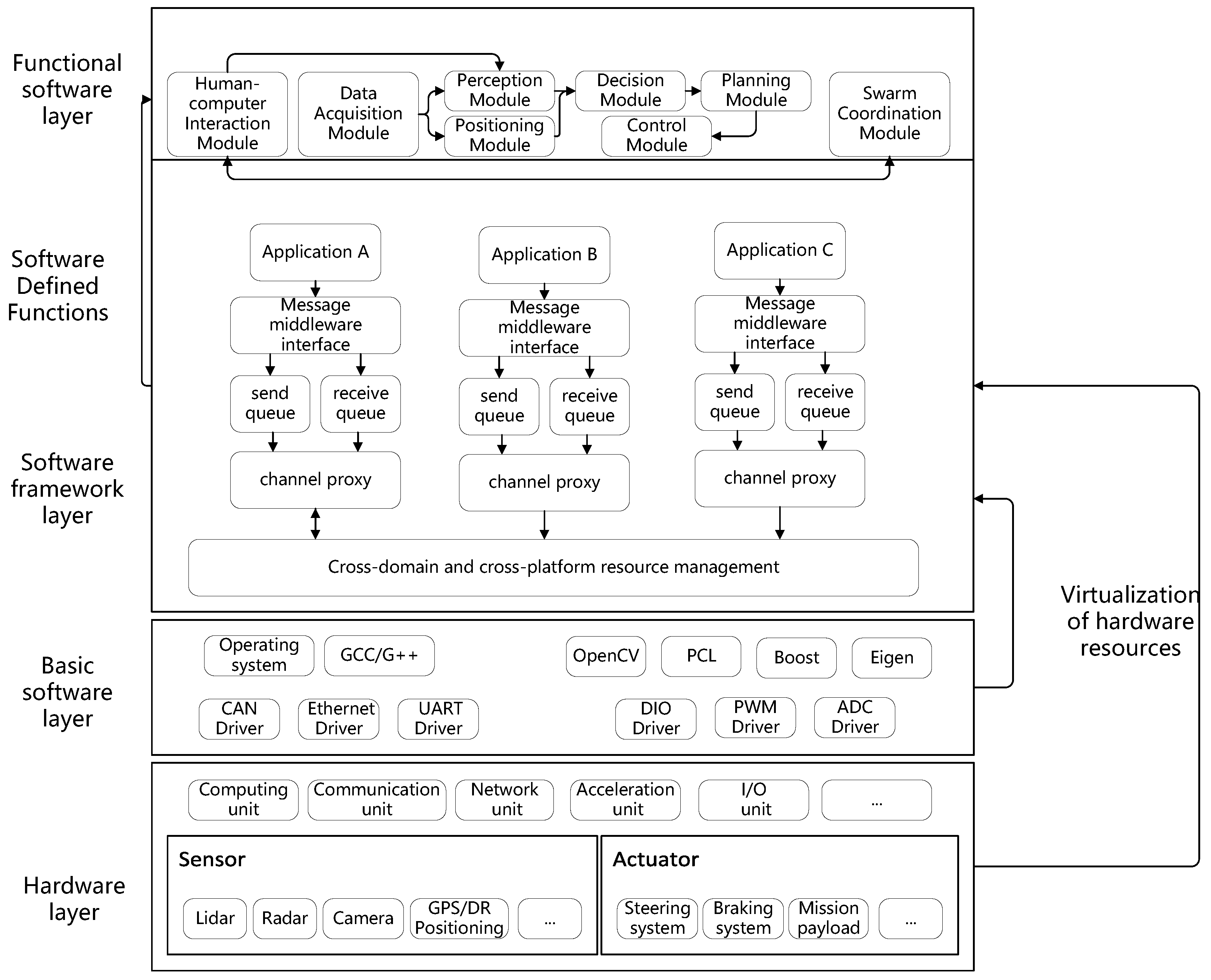
2.1. Overall Architecture

The overall architecture proposed in this paper for an unmanned swarm is divided into four layers, shown in Figure 1 from bottom to top, such as the hardware layer, basic software layer, communication middleware of single platforms and multi-platforms, and functional software layer.
The hardware layer is composed of sensors, actuators, computing units, communication units, network devices, and IO interfaces of unmanned swarms, which is some of the main factors that contribute to hardware resource heterogeneity. The sensors contain a lidar, millimeter wave radar, camera, GNSS/INS, etc. The actuators contain a steering system, braking system, mission payload system, etc.
The basic software layer is composed of the operating system, third-party software libraries, communication driver software, and IO driver software, which offer the fundamental support for the functional software and software framework. The operating system is based on Linux and its variants, such as Ubuntu, NeoKylin, Unity Operating System (UOS), etc., and the GCC/G++ compiler and Python compiler are configured to form the software development environment for the unmanned swarm. Third-party software libraries are related to functional software for processing sensor data. The communication driver software contains Ethernet communication, serial communication, CAN communication, etc. The IO driver software contains PWM, ADC, etc., which accomplishes standardized data interface for hardware devices.
The software framework layer is composed of a single platform and multi-platforms. The software framework within the platform adopts a unified and standardized technical protocol. The unified representation of resources between platforms is realized through resource virtualization, and data aggregation and distribution between multi-platforms is realized based on cross-platform resource scheduling.
The functional layer is mainly composed of application software and test software. The former contains human–machine interaction, path planning, positioning and orientation, intelligent decision, motion control, etc. The latter contains a data playback module, which supports multiple speed adjustments and is used to search for problems in the system.
Based on the above design, software and hardware can be decoupled individually, the function of an unmanned swarm is mainly defined by software, and hardware is not bound to a specific function but is abstracted into a resource pool of software or service, which contributes to the construction of a software-defined unmanned swarm.

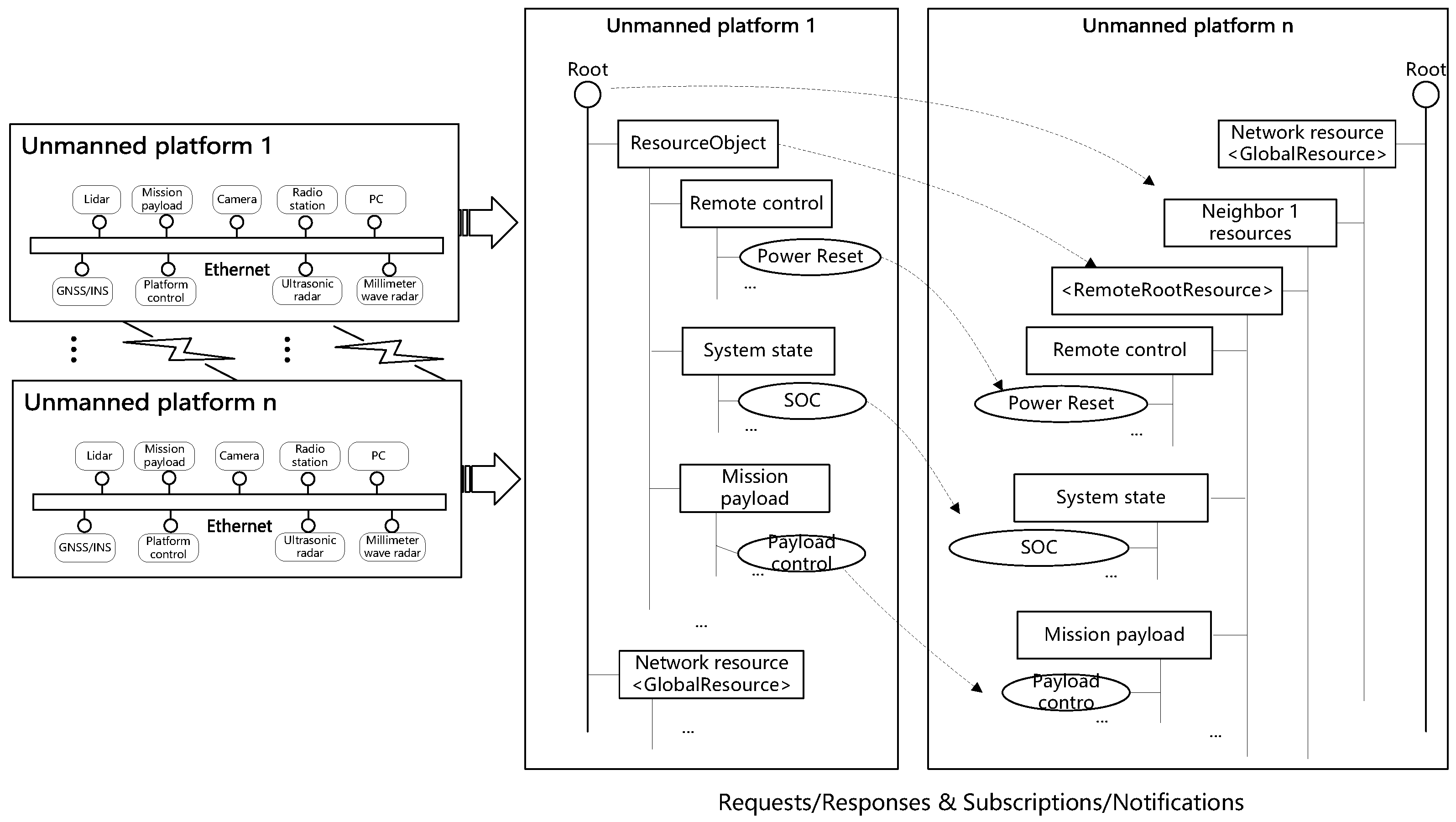
2.2. Resource Representation

Unmanned systems are often characterized by their digital nature in which all physical signals and data are converted into digital format for processing, communication, and control. With the exception of physical devices in the hardware layer, the entire design process can be considered purely digital, especially when dealing with a software-centric system. The essence of the concept involves simulating the behavior of the real-world environment in a continuous time and space context. The simulation progress is carried out by breaking down time into smaller segments through an operation cycle, shown in Figure 2. The state or discrete data are abstracted as information, corresponding to specific moments in time.
The communication between unmanned systems requires a high real-time performance. As a result, a lightweight representation of large amounts of data generated is needed to improve the efficiency of the information interaction between heterogeneous unmanned systems.
In the integration process of existing modules within a single platform system, challenges arise due to the use of different data protocols in original modules. This can involve a nested structure and class that result in non-contiguous memory addresses because of the varied nature of the data being stored. Handling large data blocks, particularly in the megabyte range, can introduce challenges related to dynamic memory allocation, copying, and performance, which may lead to failures or be time consuming. To address these issues, the structure is introduced for managing diverse data blocks, ensuring dynamic memory allocation and recycling, which mitigates the risk of memory leaks and redundant data copying. Within a single platform, a unified data protocol is adopted, consisting of a frame header followed by data. The API interface of the middleware is utilized to implement data concatenation, which involves combining multiple separate pieces of data into a single, continuous, and larger piece of data for transmission. Subsequently, the functions provided by the middleware are invoked to facilitate the actual data transmission and reception, shown in Figure 3.
For multi-platform systems, the European Telecommunications Standards Institute (ETSI) abstracted heterogeneous unmanned systems into resource trees through a tree data structure to manage and organize resources, which not only visually demonstrated the relationship between unmanned systems in an intuitive and efficient way but also offered practical benefits, such as generating unique identifiers and facilitating a resource search through a hierarchical structure. In order to facilitate the interaction between multi-platforms, a resource virtualization middleware is designed to create the root node, representing the highest-level tree structure for each respective platform, which is uniquely identified by a path such as a string or other identifier, shown in Figure 4. The resource virtualization middleware utilizes the component structure information provided in the resource template file, including details about components such as fused situation maps and the pose of the multi-platforms, constructing the corresponding resource structures.

2.3. Resource Scheduling of Single Platform

For the autonomous navigation software of a single platform, the communication middleware is proposed to satisfy requirements. The middleware is designed to manage communication between threads, processes, and the Ethernet, providing developers with a means to develop multi-threaded, multi-process, and multi-network communication programs. The middleware enables real-time data exchange among all modules in the entire system, and provides quality of service (QoS) for various types of communication data. Figure 5 shows that the communication middleware is composed of memory management, thread management, socket management, time management, and task management, deployed as an intermediate layer between operating systems and functional software on computing.
(1) Unified Programming Interface. Whether it is inter-thread, inter-process, or network communication, the same programming interface is used. Developers only need to modify the addresses to achieve fast redeployment between any devices.
(2) Single Socket Management. A communication socket can simultaneously bind (or connect) multiple internal and external ports. Developers only need to focus on the connection topology between devices and modules in the system to achieve rapid networking.
(3) No Startup Order Requirement for the Entire Network. There is no distinction between the server and client, and developers do not need to worry about whether the server is started first.
(4) Timeout Detection and Blocking Support. All types of data transmission support both blocking and non-blocking modes. Developers can use blocking mode to achieve synchronization triggers between multiple threads, processes, and networks.
(5) Support for Multiple Communication Modes. The point-to-point and publish–subscribe models are allowed, enabling the rapid construction of one-to-one, one-to-many, and many-to-many network topologies.
According to the complexity of the task, the autonomous navigation function module is divided into several sub-modules, and each sub-module realizes independent functions, supports the plug-and-play of the functional module, and completely liberates the developer from heavy work. Functional modules are deployed on a computer, and each runs in an independent process, which, in turn, contains multiple threads, each thread achieving relatively independent functions, shown in Figure 6. For example, the multi-line lidar modeling module is realized by two threads: one thread realizes the function of data acquisition, and the other thread realizes the function of modeling, such as ground segmentation. The orientation module is implemented by one thread. The decision module is realized by four threads, which are input acquisition, local path planning, control command delivery, and path display. The platform control module is realized by three threads, which can collect control commands, send them to the chassis controller, and collect the chassis status. The human–machine interaction module is realized by two threads: one thread realizes the communication function with the console and receives the task path and remote control commands, and the other thread realizes the collection and feedback of the platform state.

2.4. Resource Scheduling of Muti-Platform

The status data and control data of unmanned platforms are expressed in the form of resources. However, the lack of universality in communication protocols between different unmanned platforms can indeed present challenges when attempting to achieve interconnectivity and interoperability. Therefore, a standard approach must be used to collect, store, and transfer information of multiple types. In this paper, resource virtualization for a multi-platform is proposed. The resource tree structure of a neighbor unmanned platform is registered locally, and network resources are formed locally to represent neighbor resources, as shown in Figure 7.
The construction of a middleware for cross-platform resource interoperability is a strategic approach for enabling effective resources scheduling and interaction by introducing request and response and subscription and notification. The former is used for periodic data, such as the platform position and platform or payload control commands. The latter is mainly used for conditional data, such as the delivery of the mission path, driving mode switching, and device power. Based on the establishment of a resource tree, the local platform can obtain the resource tree structure of the neighbor system. The neighbor resource is essentially a reference of the local resource in other systems.
In the implementation of cross-platform request and response, platforms can initiate requests for network resources through distributed directories, and the neighbor platforms will respond to the source platform according to the requests. However, due to a limited communication range, platforms that are relatively far apart cannot directly communicate with each other. With the help of a distributed directory, platforms select a suitable link in the dynamic network topology and forward the request to neighboring platforms. The neighboring platform receives the request, processes it, and then forwards the response back to the source platform after completing the processing.
The process of cross-platform resource request and response is as follows, shown in Figure 8.
(1) The network proxy of the resource middleware on the unmanned platform 1 detects the presence of neighbor unmanned platform 2 and communicates this information that the neighbor unmanned platform 2 accesses to the distributed directory management.
(2) The resource middleware of unmanned platform 1 uses distributed resource tree management to request the resource tree structure of neighboring unmanned platform 2 through cross-platform methods.
(3) Neighbor unmanned platform 2 records the current state after receiving the request, traverses its own resource tree, and records the structure of the resource required. After the traversal is complete, the entire resource structure is sent to unmanned platform 1.
(4) After receiving the resource tree structure of neighbor unmanned platform 2, the distributed directory management of unmanned platform 1 registers the resources of neighbor unmanned platform 2 locally as neighbor resources to complete the request and response.
For conditional data, if there are only requests and responses from network resources, each platform has to constantly send requests to monitor whether the resources interested have changed. This method is not only inefficient but also occupies network bandwidth and computing resources. Therefore, the subscription and notification of cross-platform resources is proposed in this paper. Similar to cross-platform resource request and response, platforms can subscribe to network resources interested. The resource middleware through the network proxy selects a suitable path and forwards a subscription to neighboring platforms. When the subscribed resource event is triggered, the neighboring platform will again use the network proxy and the established path to notify the source platform about the corresponding resource changes. In this mode, platforms will only receive relevant data when the resources interested obtain corresponding changes, greatly reducing the load of the network and platform. Figure 8 illustrates the process of cross-platform subscription and notification.
(1) Unmanned platform 1 sends a request to neighbor unmanned platform 2 to subscribe to the resource tree. Neighbor unmanned platform 2 accepts the request and registers it as a subscription event.
(2) A new resource is created on neighbor unmanned platform 2, and the structure of the new resource is sent to unmanned platform 1.
(3) Unmanned platform 1 receives new resources from unattended neighbor platform 2 and sends them to distributed resource tree management, which creates corresponding neighbor resources through universal resource management.

2.5. Dynamic Storage and Management

To back up and store data, a unified global data space is established for the entire system using a real-time database, named MongoDB, providing a unified data access interface for multi-platforms. It is responsible for data sharing and exchange among components in the system, including two major categories, such as periodic data and conditional data. The data stored in the real-time database are stored in circular queues. Each functional module is allocated an input circular queue and an output circular queue. The functional module continuously extracts data from the input circular queue and decides whether to clear the data based on its own QoS. Messages are formatted as internal communication frames, storing communication data packets. When extracting data, they are divided into two parts.
Frame Header Information. The frame header contains information such as the source platform ID and data type, which plays a crucial role in identifying and categorizing the data being transmitted.
Data information. This is the actual payload of the communication packet, which contains the actual data being transmitted.
In order to improve the efficiency of data exchange, a B-tree index is used in this paper, known for efficient locating and high utilization. It allows for the efficient retrieval and manipulation of data in the database.

3. Results

3.1. Kinematic Model

The unmanned platform has six degrees of freedom, including the x coordinate, y coordinate, z coordinate, pitch angle, yaw angle and roll angle. In this paper, it is assumed that the unmanned platform only moves in a plane, so the z-direction value, pitch angle, and roll angle are 0. Therefore, the x coordinate, y coordinate, yaw angle, velocity, and angular velocity can be selected to create a five-dimensional state vector. According to the motion law of the unmanned platform, the kinematics model of the unmanned platform can be calculated, as shown in Formula (1):
p ( t k + 1 ) = x ( t k + 1 ) y ( t k + 1 ) φ ( t k + 1 ) v ( t k + 1 ) ω ( t k + 1 ) = x ( t k ) + v ( t k ) · c o s ( φ ( t k ) ) · Δ t y ( t k ) + v ( t k ) · s i n ( φ ( t k ) ) · Δ t φ ( t k ) + ω ( t k ) · Δ t v ( t k ) + a ( t k ) · Δ t ω ( t k ) + α ( t k ) · Δ t = F · p ( t k ) + B · u ( t k )
where x ( t k ) and y ( t k ) are the x-direction and y-direction coordinates of the unmanned platform at time t k , respectively. φ ( t k ) is yaw angle. v ( t k ) is velocity. ω ( t k ) is angle velocity. a ( t k ) is linear acceleration, and α ( t k ) is angular acceleration. It is assumed in this paper that the unmanned platform moves at a uniform speed within a sampling time, so both a ( t k ) and α ( t k ) are 0. The matrix F = f i a g { 1 , 1 , 1 , 0 , 0 } . The matrix B is shown in Formula (2).
B = c o s ( φ ( t k ) ) · Δ t 0 s i n ( φ ( t k ) ) · Δ t 0 0 Δ t 1 0 0 1
The control vector u ( t k ) is composed of v ( t k ) and ω ( t k ) , as shown in Formula (3).
u ( t k ) = v ( t k ) ω ( t k )
The DWA (Dynamic Window Approach) algorithm is introduced for implementing local path planning for the unmanned platforms [13]. The core idea is to sample within the global space composed of velocity and angular velocity and simulate the motion trajectories of the unmanned platform at the current velocity for a certain period of time. Using optimal control theory, the velocity and angular velocity area selected corresponding to the optimal trajectory from multiple sets of trajectories to control the motion of the unmanned platform.
The velocity and acceleration of unmanned platforms are limited by physical limits, which can be expressed in Formula (4). Among them, V s a f e is the maximum speed and angular velocity to ensure that no obstacles are encountered, and V l i m is the maximum speed that the unmanned platform can reach, which ensures the state space of velocity and angular velocity.
V s a f e = ( v , ω ) v 2 · dist ( v , ω ) · a 1 m a x & ω 2 · dist ( v , ω ) · α 1 m a x V l i m = ( v , ω ) v ϵ [ v 0 a 1 m a x · t , v 0 + a 2 m a x · t ] & ω ϵ [ ω 0 α 1 m a x · t , ω 0 + α 2 m a x · t ]
where a 1 m a x and a 2 m a x are the maximum linear deceleration and maximum linear acceleration of the unmanned platform, respectively. α 1 m a x and α 2 m a x are the maximum angular deceleration and maximum angular acceleration of the unmanned platform, respectively. dist ( v , ω ) is the shortest distance between the predicted trajectory and the obstacle.
As a result, the cost function can be expressed as Formula (5):
G ( v , ω ) = δ · heading ( v , ω ) + β · distance ( v , ω ) + γ · velocity ( v , ω )
where ( v , ω ) ϵ { V s a f e & V l i m } is the velocity and angular velocity of the current sampling. heading is the angle difference between the predicted trajectory and the target position. distance is the distance between the predicted trajectory and the obstacle, and the respective weights of δ , β , and γ .

3.2. Simulation Experiment

To verify the software framework proposed in this paper, a hardware-in-the-loop simulation system is created. In terms of hardware, 16 heterogeneous unmanned swarms are planned to be used, of which 5 edge computing devices are selected to simulate the UGV controller, 10 edge computing devices are selected to simulate the UAV controller, and 1 edge computing device is selected to simulate a command and control system to issue mission instructions and monitor the status of various heterogeneous unmanned systems. The data interaction between unmanned swarms is realized through Gigabit Ethernet switches, as shown in Figure 9. The hardware specifications of the unmanned swarm are shown in Table 1.
In terms of software, all 16 nodes mentioned above are deployed with the software architecture proposed in this paper, and the UGV and UAV controllers are deployed with corresponding path planning algorithm. After the control center issues the task instruction of the unmanned swarm, it is analyzed by the task-understanding module and sent to the UGV swarm composed of 5 unmanned platforms and the UAV swarm composed of 10 unmanned platforms. The unmanned platform realizes autonomous navigation and driving according to the path planning algorithm mentioned above. Each unmanned platform uploads state data, sensor data, and task instructions to the proposed software architecture, and builds a resource tree topology locally as the root node. Other platforms in the neighborhood register in the global node through the network to build an entire resource tree, which forms a global resource pool. The unmanned swarm can obtain the messages of other unmanned platforms in the neighborhood through the method of request and response and subscription and notification, as shown in Figure 10.
The resource tree of the unmanned platform mainly includes two types: the periodic data mainly including the unmanned platform position, orientation, linear velocity, angular velocity, etc., and the event data mainly based on the task instruction. The experimental results show that the global traffic of the entire network is 56.07 KBps, the egress traffic is 14.89 KBps, the ingress traffic is 1.31 KBps, the number of requests and responses is divided into 25 instances, and the number of notifications is 81,297. Obviously, this is because the data mounted on the resource tree are mainly periodic data, as shown in Figure 11. In addition, it takes 11.95015 milliseconds from the mission command issued by the command center to the receipt of the control information by the heterogeneous unmanned swarm, which fully meets the needs of air-to-ground unmanned swarms in performing collaborative tasks.

4. Discussion

By conducting a practical demonstration and rigorous verification of a formation driving system integration within a hardware-in-the-loop environment, the proposed software architecture in this paper shows its ability to facilitate seamless data exchange and meet the real-time requirements of unmanned systems. Simultaneously, the proposed software architecture has the following advantages over the classic ROS architecture.
Generalization. ROS is mainly for monomeric robots or homogeneous group robots, and relies on traditional operating systems, such as Ubuntu, but cannot be adapted to the common computing equipment such as Phytium, Loongson, and Rockchip and operating systems such as Kylin and Unity in China. The proposed software architecture in this paper has been successfully adapted and integrated with common hardware platforms and operating systems in China due to its universal design pattern, providing valuable experience for promoting cross-domain heterogeneous unmanned swarm collaboration.
Robustness. Implementing ROS can be resource-intensive in terms of computing power and memory usage. The overhead associated with ROS communication mechanisms and managing multiple nodes can lead to increased hardware requirements, especially for unmanned swarms. The proposed software architecture in this paper adopts a lightweight design, and the memory and power occupied by transmitting the same data are less. At the same time, without using the master node, a distributed multi-platform resource management method based on neighbors is proposed, which can support the decentralized management of cross-platform resources for an unmanned swarm of any scale.
Real-Time Performance. The bottom layer of ROS uses a UDP/TCP communication protocol for data transmission, and the proposed software architecture in this paper uses shared memory within the platform, while UDP/TCP communication is used between platforms, which has a higher data transmission efficiency and reduces communication delay.
Standardization. While ROS has a vibrant community, some areas of the framework, such as naming conventions, message formats, and package structures, may lack standardized practices, making code integration and sharing more challenging. The proposed software architecture in this paper adopts a unified structure definition within a platform, and uses a resource tree between platforms to perform the unified abstraction and representation of data resources, which is universal.
However, only 15 unmanned heterogeneous platforms are implemented to conduct formation driving tasks, including 5 UGVs and 10 UAVs. When the number of unmanned swarm reaches hundreds, the proposed architecture may face complex communication problems and real-time resource synchronization problems, which will be the focus of future research. In addition, the privacy and security of the data exchange of a heterogeneous unmanned swarm are also key considerations for software architecture in the future.

5. Conclusions

This paper introduces a distributed software architecture designed for unmanned swarm systems that achieves message abstraction representation through the concept of resources. The resource scheduling within a single platform is accomplished through communication between processes and threads utilizing shared memory. By registering the resource tree structure of neighboring platforms locally and mapping it to form a representation of the remote resource tree of the neighbors, cross-platform data scheduling and management are realized. The resources pool of hardware data is constructed to decouple hardware resources from software functionality, which achieves the realization of a software-defined unmanned swarm, wherein software is harnessed to empower and enhance the capabilities of hardware components. Particularly, the unmanned architecture in this article is applicable to both monolithic systems and swarm systems that consist of multiple platforms. The architecture has the ability to unify the design across both the micro-environment within a single platform and the macro-environment of the entire unmanned swarm, which brings coherence and consistency to the systems’ behavior at different scales. At the same time, this architecture has been customized and implemented to function on various operating systems, including Ubuntu, Kylin, and Unity. Additionally, it has been adapted to work with common computing hardware like Phytium, Loongson, and Rockchip, which are prevalent in China. This adaptation showcases the architecture’s versatility and adaptation to different operation environments and hardware platforms. Finally, a hardware-in-the-loop simulation environment was constructed to verify the proposed approach using the formation method. The experiment obviously proves that this architecture can be applied in the software development of unmanned platform control systems, demonstrating good scalability and flexibility. Due to the decoupling of functional units, it supports parallel development and incremental development, allowing for reuse across the entire lifecycle, including design, testing, and validation. In the future, the software architecture proposed in this paper can be used in scenarios such as fire detection, meteorological information collection, and emergency rescue through a heterogeneous swarm composed of a fixed-wing UAV, rotary-wing UAV or UGV.

Author Contributions

Conceptualization, X.A.; Methodology, W.S.; Software, X.A. and X.Y.; Formal analysis, L.H.; Investigation, Z.L.; Data curation, T.Y.; Supervision, Z.S. All authors have read and agreed to the published version of the manuscript.

Funding

This research received no external funding.

Data Availability Statement

Data are contained within the article.

Conflicts of Interest

The authors declare no conflict of interest.

References

  1. Dai, H.; Yi, X.; Wang, Y.; Wang, Z.; Yang, X. Parallel Learning Architecture of micROS Powering the Ability of Life-Long Autonomous Learning. J. Comput. Res. Dev. 2019, 56, 49–57. [Google Scholar]
  2. Kranz, M.; Rusu, R.B.; Maldonado, A.; Beetz, M.; Schmidt, A. A player/stage system for context-aware intelligent environments. Proc. UbiSys 2006, 6, 17–21. [Google Scholar]
  3. Michal, D.S.; Etzkorn, L. A comparison of player/stage/gazebo and microsoft robotics developer studio. In Proceedings of the 49th Annual Southeast Regional Conference, Kennesaw, GA, USA, 24–26 March 2011; pp. 60–66. [Google Scholar]
  4. Matta-Gómez, A.; Del Cerro, J.; Barrientos, A. Multi-robot data mapping simulation by using microsoft robotics developer studio. Simul. Model. Pract. Theory 2014, 49, 305–319. [Google Scholar] [CrossRef]
  5. Kraetzschmar, G.; Utz, H.; Sablatnög, S.; Enderle, S.; Palm, G. Miro-middleware for cooperative robotics. In Proceedings of the RoboCup 2001: Robot Soccer World Cup V 5; Springer: Berlin/Heidelberg, Germany, 2002; pp. 411–416. [Google Scholar]
  6. Albus, J.S. 4D/RCS: A reference model architecture for intelligent unmanned ground vehicles. Proc. SPIE 2002, 4715, 303–310. [Google Scholar]
  7. Quigley, M.; Conley, K.; Gerkey, B.; Faust, J.; Foote, T.; Leibs, J.; Wheeler, R.; Ng, A.Y. ROS: An open-source Robot Operating System. In Proceedings of the ICRA Workshop on Open Source Software, Kobe, Japan, 12–17 May 2009; Volume 3, p. 5. [Google Scholar]
  8. Kent, D.; Galluzzo, T.; Bosscher, P.; Bowman, W. Robotic manipulation and haptic feedback via high speed messaging with the joint architecture for un-manned systems (jaus). In Proceedings of the AUVSI Unmanned Systems Conference, Anaheim, CA, USA, 3–5 August 2004. [Google Scholar]
  9. Pardo-Castellote, G. Omg data-distribution service: Architectural overview. In Proceedings of the 23rd International Conference on Distributed Computing Systems Workshops, Providence, RI, USA, 19–22 May 2003; pp. 200–206. [Google Scholar]
  10. Sandmann, G.; Thompson, R. Development of AUTOSAR software components within model-based design. Development 2008, 1, 0383. [Google Scholar]
  11. Jones, J. System of Systems Integration Technology and Experimentation (SoSITE); Defense Advanced Research Projects Agency: Arlington, VA, USA, 2019. [Google Scholar]
  12. Yang, X.; Dai, H.; Yi, X.; Wang, Y.; Yang, S.; Zhang, B.; Wang, Z.; Zhou, Y.; Peng, X. micROS: A morphable, intelligent and collective robot operating system. Robot. Biomim. 2016, 3, 21. [Google Scholar] [CrossRef] [PubMed]
  13. Fox, D.; Burgard, W.; Thrun, S. The dynamic window approach to collision avoidance. IEEE Robot. Autom. Mag. 1997, 4, 23–33. [Google Scholar] [CrossRef]
Figure 1. The schematic diagram of overall architecture.
Electronics 12 03739 g001
Figure 2. The schematic diagram of digital system.
Electronics 12 03739 g002
Figure 3. The schematic diagram of single-platform resources.
Electronics 12 03739 g003
Figure 4. The structure of resource tree.
Electronics 12 03739 g004
Figure 5. The schematic diagram of communication middleware.
Electronics 12 03739 g005
Figure 6. The schematic diagram of unmanned platform control system.
Electronics 12 03739 g006
Figure 7. The schematic diagram of cross-platform resource virtualization.
Electronics 12 03739 g007
Figure 8. The schematic diagram of cross-platform resource schedule. Red arrows indicate data transmission through subscription and notification methods, and blue arrows indicate data transmission through request and response methods.
Electronics 12 03739 g008
Figure 9. The hardware composition diagram of hardware-in-the-loop simulation system.
Electronics 12 03739 g009
Figure 10. The schematic diagram of hardware-in-the-loop simulation process.
Electronics 12 03739 g010
Figure 11. The diagram of unmanned system workflow. ((a) indicates that functional software of 15 unmanned platform nodes is started through SSH remote access method of MobaXterm software in the simulation server. The green part indicates that data synchronization between unmanned platform nodes is successful. (b) indicates that the unmanned system realizes formation action according to the issued task. (c) represents the network topology during the movement of the unmanned system, and (d) represents the resource tree constructed by the unmanned platform, respectively).
Electronics 12 03739 g011
Table 1. The specifications of a hardware-in-the-loop simulation system.
DevicesSpecifications
Simulation serverOperating systemWindows
MemoryDDR4 64 GB
CPUXeon E5-2667v3@3.2 GHz
GPUNvidia Titan X (Pascal)
UGV 5Operating systemKylin
MemoryDDR4 32 GB
CPUPhytium D2000@2.6 GHz
GPUCambricon MLU220
UAV 10Operating systemKylin
MemoryDDR4 16 GB
CPUIntel i7 6700 K
GPUNVIDIA GeForce GTX 670
UGV (1-4)/UAV (1-9)Operating systemUbuntu18.04 OR Ubuntu20.04
MemoryDDR4 16 GB
CPUARM A78AE v8.2
GPUNVIDIA Ampere architecture GPU with 64 Tensor Cores
Disclaimer/Publisher’s Note: The statements, opinions and data contained in all publications are solely those of the individual author(s) and contributor(s) and not of MDPI and/or the editor(s). MDPI and/or the editor(s) disclaim responsibility for any injury to people or property resulting from any ideas, methods, instructions or products referred to in the content.

