
Sensorless Control Method for SPMSMs Based on Improved Sliding Mode Reaching Rate

Abstract
:1. Introduction
2. Mathematical Model
3. Design of Improved Reaching Rate
3.1. Traditional Reaching Rate
3.2. Improved Reaching Rate
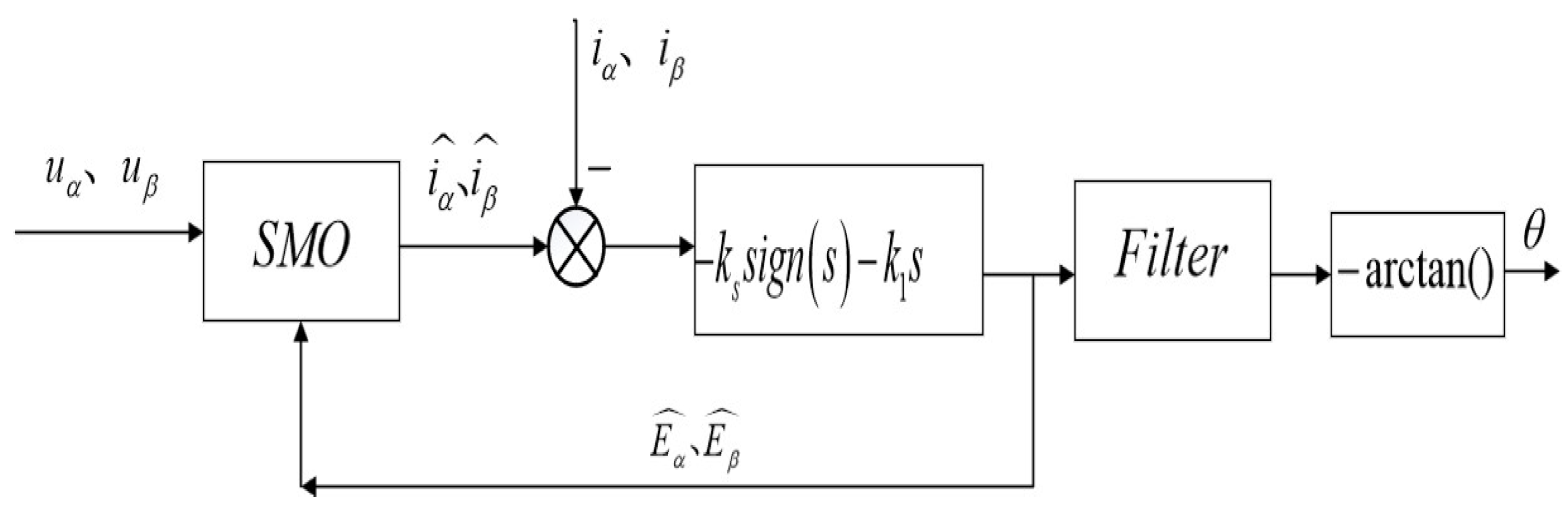
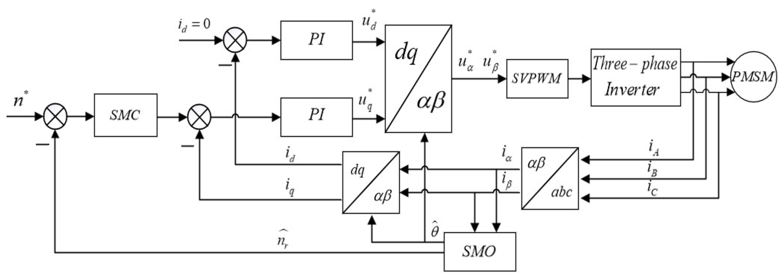
4. Construction of System
5. Simulation and Experimental
5.1. Simulation and Comparison
5.1.1. Simulation Modeling
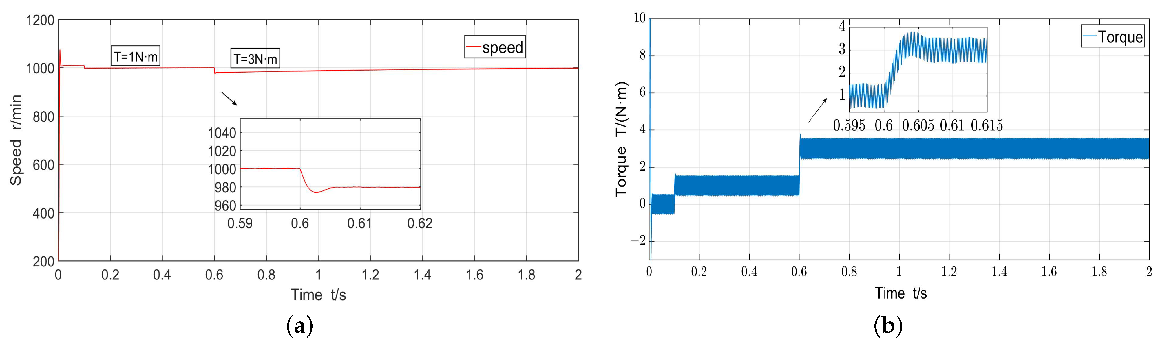
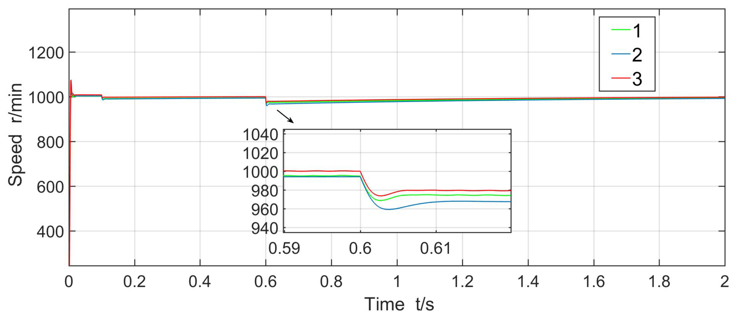
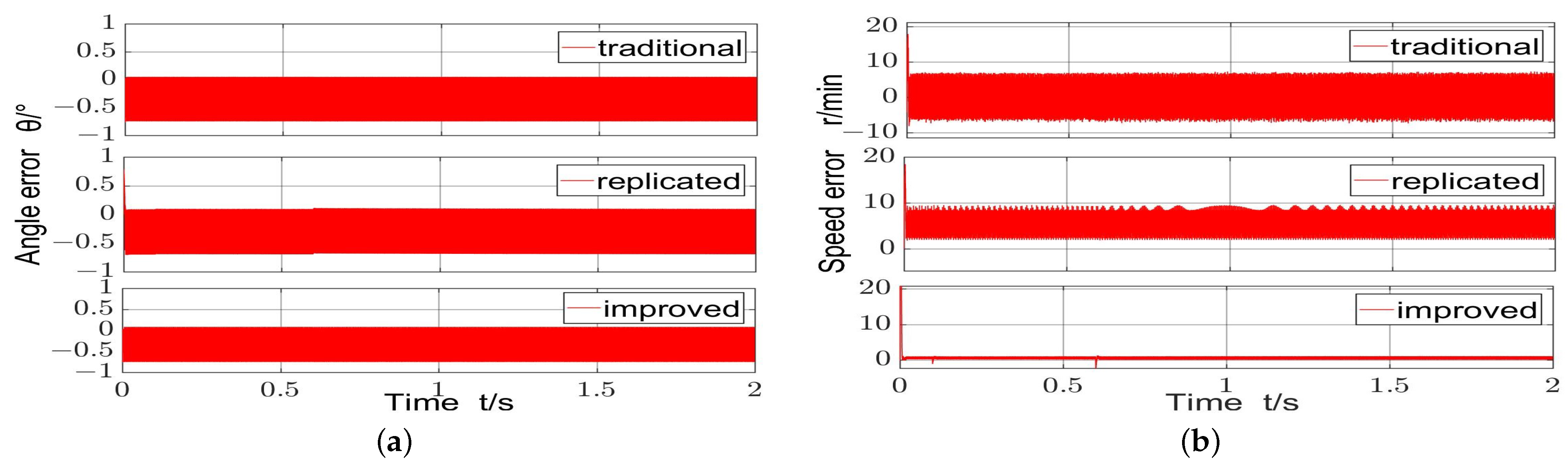
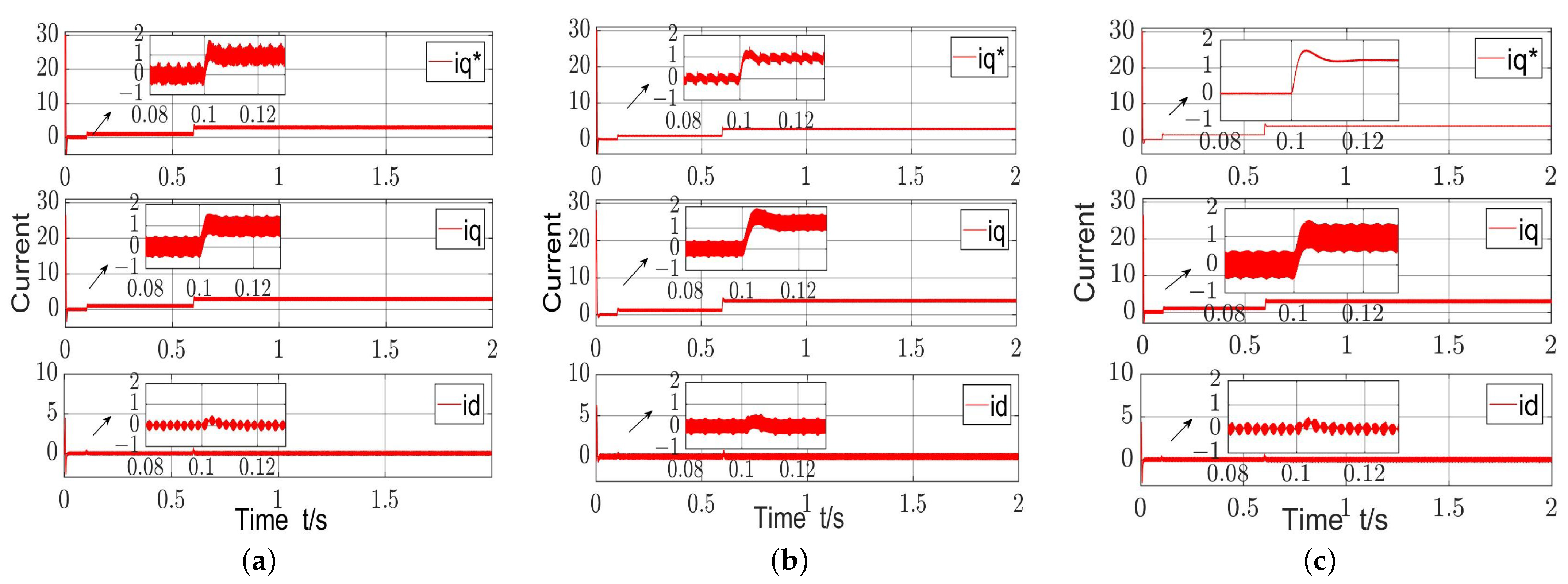
5.1.2. Comparisons of SM Algorithms
5.2. Experimental Verification
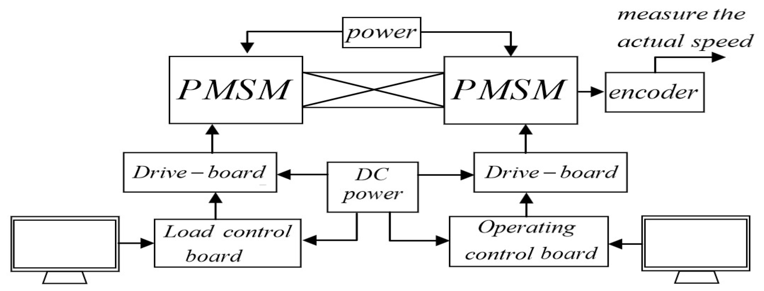
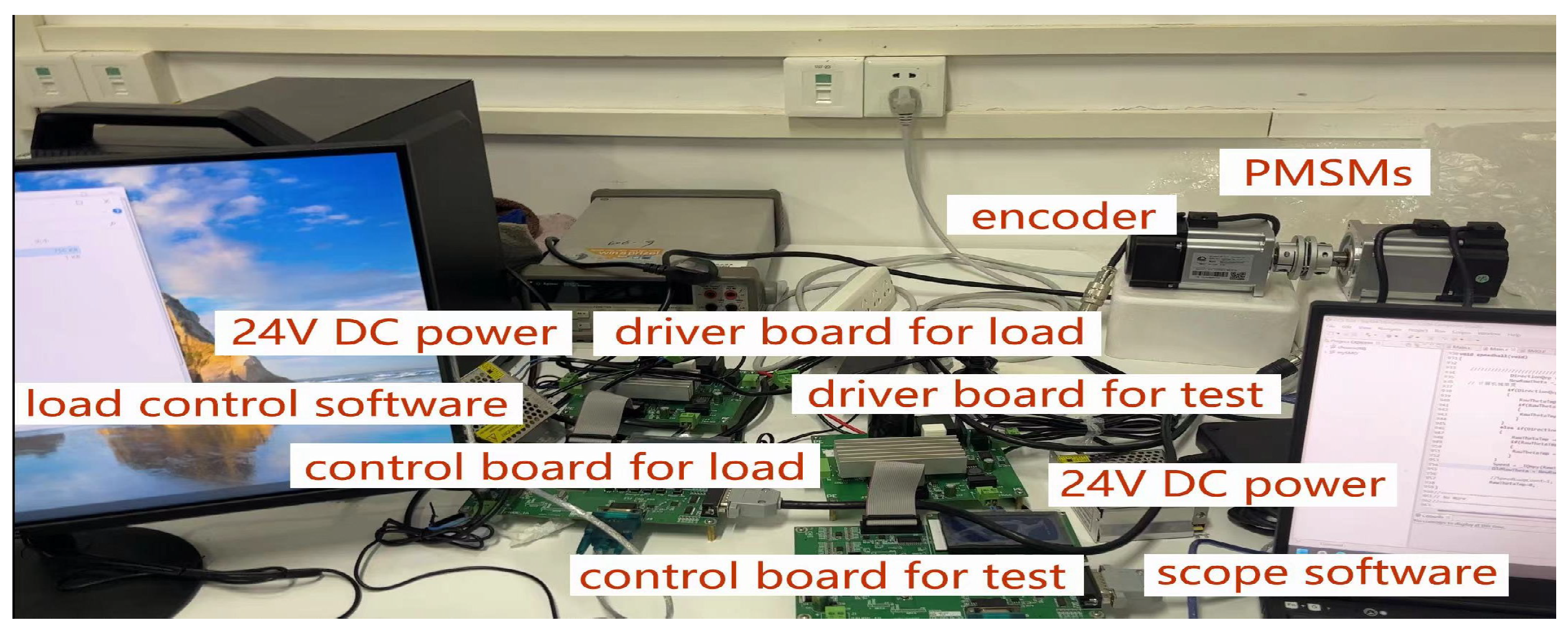
5.2.1. Construction of Towing Test Platform
5.2.2. Comparative Experiment
6. Conclusions
Author Contributions
Funding
Data Availability Statement
Conflicts of Interest
References
- Vaez-Zadeh, S. Control of Permanent Magnet Synchronous Motors; Oxford University Press: Oxford, UK, 2018. [Google Scholar]
- Liu, J.L.; Xiao, F.; Shen, Y.; Mai, Z.Q.; Li, C.R. Research review on Sensorless control technology of permanent magnet synchronous motor. J. Electrotech. Eng. 2017, 32, 76–88. [Google Scholar] [CrossRef]
- Zhang, G.Q.; Wang, G.L.; Xu, D.G. Saliency-based position sensorless control methods for PMSM drives—A review. Chin. J. Electr. Eng. 2017, 3, 14–23. [Google Scholar] [CrossRef]
- Liu, Z.H.; Nie, J.; Wei, H.L.; Chen, L.; Wu, F.M. Second-order ESO-based current sensor fault-tolerant strategy for sensorless control of PMSM with B-phase current. IEEE/ASME Trans. Mechatron. 2022, 27, 5427–5438. [Google Scholar] [CrossRef]
- Yin, Z.G.; Li, W.; Zhang, Y.Q.; Tang, R.J. Model predictive torque control based on a disturbance observer for induction motor drives. In Proceedings of the 2019 14th IEEE Conference on Industrial Electronics and Applications (ICIEA), Xi’an, China, 19–21 June 2019; pp. 1871–1875. [Google Scholar] [CrossRef]
- Apte, A.; Joshi, V.A.; Mehta, H.; Walambe, R. Disturbance-observer-based sensorless control of PMSM using integral state feedback controller. IEEE Trans. Power Electron. 2019, 35, 6082–6090. [Google Scholar] [CrossRef]
- Lu, X.Q.; Lin, H.Y.; Han, J.L. The disturbance observer of permanent magnet synchronous motor controlled without position sensor. Chin. J. Electr. Eng. 2016, 36, 1387–1394. [Google Scholar] [CrossRef]
- Zhou, Y.; Tang, J.; Sheng, M.L.; Zhang, T.; Liu, C. Sensorless control of permanent magnet synchronous motor based on extended state observer. Micromotor 2018, 51, 44–49. [Google Scholar] [CrossRef]
- Chen, S.; Ding, W.; Hu, R.M.; Wu, X.; Shi, S. Sensorless Control of PMSM Drives Using Reduced Order Quasi Resonant-Based ESO and Newton–Raphson Method-Based PLL. IEEE Trans. Power Electron. 2022, 38, 229–244. [Google Scholar] [CrossRef]
- Yu, B.; Shen, A.; Chen, B.; Luo, X.; Tang, Q.; Xu, J.; Zhu, M. A Compensation Strategy of Flux Linkage Observer in SPMSM Sensorless Drives Based on Linear Extended State Observer. IEEE Trans. Energy Convers. 2022, 37, 824–831. [Google Scholar] [CrossRef]
- Zhang, T.; Xu, Z.; Li, J.; Zhang, H.; Gerada, C. A Third-Order Super-Twisting Extended State Observer for Dynamic Performance Enhancement of Sensorless IPMSM Drives. IEEE Trans. Ind. Electron. 2020, 67, 5948–5958. [Google Scholar] [CrossRef]
- Zhang, Y.; Jin, J.; Huang, L. Model-Free Predictive Current Control of PMSM Drives Based on Extended State Observer Using Ultralocal Model. IEEE Trans. Ind. Electron. 2021, 68, 993–1003. [Google Scholar] [CrossRef]
- Volpato, C.J.; Vieira, R.P. Adaptive Full-Order Observer Analysis and Design for Sensorless Interior Permanent Magnet Synchronous Motors Drives. IEEE Trans. Ind. Electron. 2021, 68, 6527–6536. [Google Scholar] [CrossRef]
- Sreejith, R.; Singh, B. Sensorless Predictive Current Control of PMSM EV Drive Using DSOGI-FLL Based Sliding Mode Observer. IEEE Trans. Ind. Electron. 2021, 68, 5537–5547. [Google Scholar] [CrossRef]
- Ye, S.C.; Yao, X.X. An Enhanced SMO-Based Permanent-Magnet Synchronous Machine Sensorless Drive Scheme With Current Measurement Error Compensation. IEEE J. Emerg. Sel. Top. Power Electron. 2021, 9, 4407–4419. [Google Scholar] [CrossRef]
- Xu, W.J.; Qu, S.C.; Zhao, L.; Zhang, H.R. An Improved Adaptive Sliding Mode Observer for Middle- and High-Speed Rotor Tracking. IEEE Trans. Power Electron. 2021, 36, 1043–1053. [Google Scholar] [CrossRef]
- Ren, N.N.; Fan, L.; Zhang, Z. Sensorless PMSM Control with Sliding Mode Observer Based on Sigmoid Function. J. Electr. Eng. Technol. 2021, 16, 933–939. [Google Scholar] [CrossRef]
- Yin, Z.G.; Zhang, Y.P.; Cao, X.P.; Yuan, D.S.; Liu, J. Estimated Position Error Suppression Using Novel PLL for IPMSM Sensorless Drives Based on Full-Order SMO. IEEE Trans. Power Electron. 2022, 37, 4463–4474. [Google Scholar] [CrossRef]
- Ding, H.; Zou, X.; Li, J. Sensorless Control Strategy of Permanent Magnet Synchronous Motor Based on Fuzzy Sliding Mode Observer. IEEE Access 2022, 10, 36743–36752. [Google Scholar] [CrossRef]
- Lu, W.; Zheng, D.; Lu, Y.; Lu, K.; Guo, L.; Yan, W.; Luo, J. New Sensorless Vector Control System With High Load Capacity Based on Improved SMO and Improved FOO. IEEE Access 2021, 9, 40716–40727. [Google Scholar] [CrossRef]
- Lascu, C.; Andreescu, G.-D. PLL Position and Speed Observer With Integrated Current Observer for Sensorless PMSM Drives. IEEE Trans. Ind. Electron. 2020, 67, 5990–5999. [Google Scholar] [CrossRef]
- Yang, H.; Tang, J.W.; Chien, Y.R. Application of new sliding mode control in vector control of PMSM. IEICE Electron. Express 2022, 19, 20220156. [Google Scholar] [CrossRef]
- Huang, Y.B.; Wu, F. A Sensorless Control Method for Permanent Magnet Synchronous Motor Based on Fractional-Order Sliding Mode Observer. In Proceedings of the 2020 IEEE 5th Information Technology and Mechatronics Engineering Conference (ITOEC 2020), Chongqing, China, 12–14 June 2020; pp. 1536–1542. [Google Scholar] [CrossRef]
- Liu, J.; Li, H.W.; Deng, Y.T. Sliding mode control of permanent magnet synchronous motor based on new approach law and disturbance observer. J. Eng. Sci. 2017, 39, 933–944. [Google Scholar] [CrossRef]
- Li, Y.; Hu, H.; Shi, P. A Review of Position Sensorless Compound Control for PMSM Drives. World Electr. Veh. J. 2023, 14, 34. [Google Scholar] [CrossRef]
- Hung, J.Y.; Gao, W.; Hung, J.C. Variable structure control: A survey. IEEE Trans. Ind. Electron. 1993, 40, 45–55. [Google Scholar] [CrossRef]


| Parameters | Values |
|---|---|
| Number of poles | 5 |
| Stator inductance /mH | 6.552 |
| Stator resistance | 0.901 |
| Flux /Wb | 0.06912 |
| Damping factor | |
| Inertia J/(kg·m) | |
| Rated torque (N·m) | 2.4 |
| Peak torque (N·m) | 7.2 |
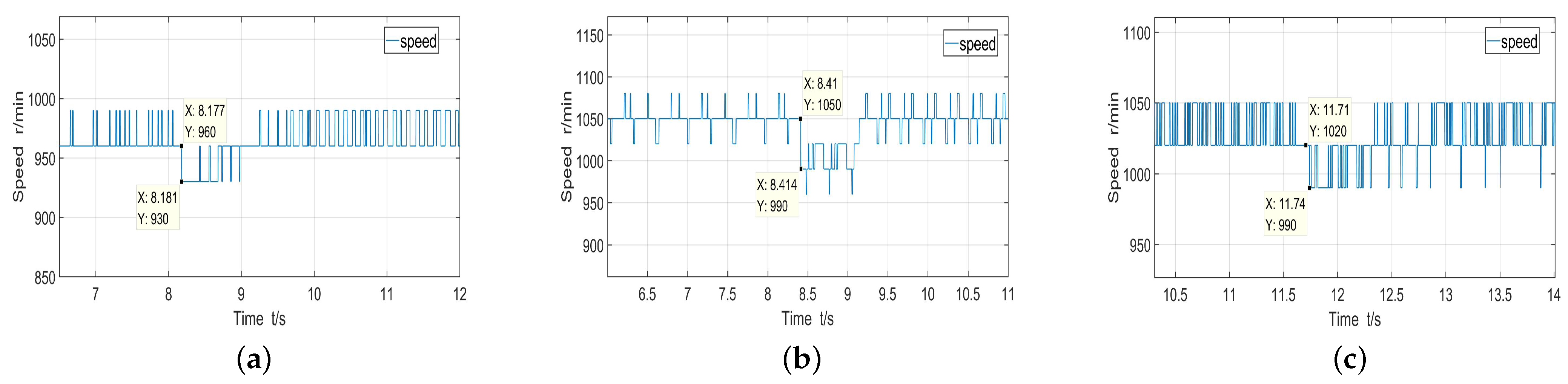
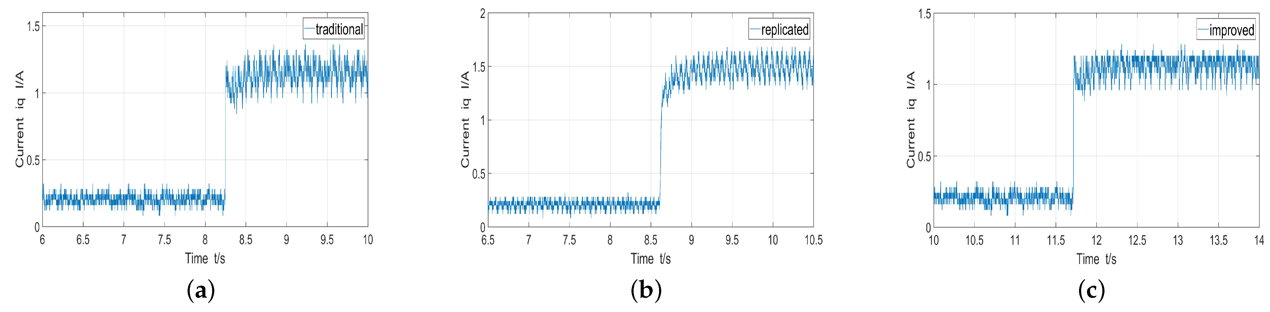
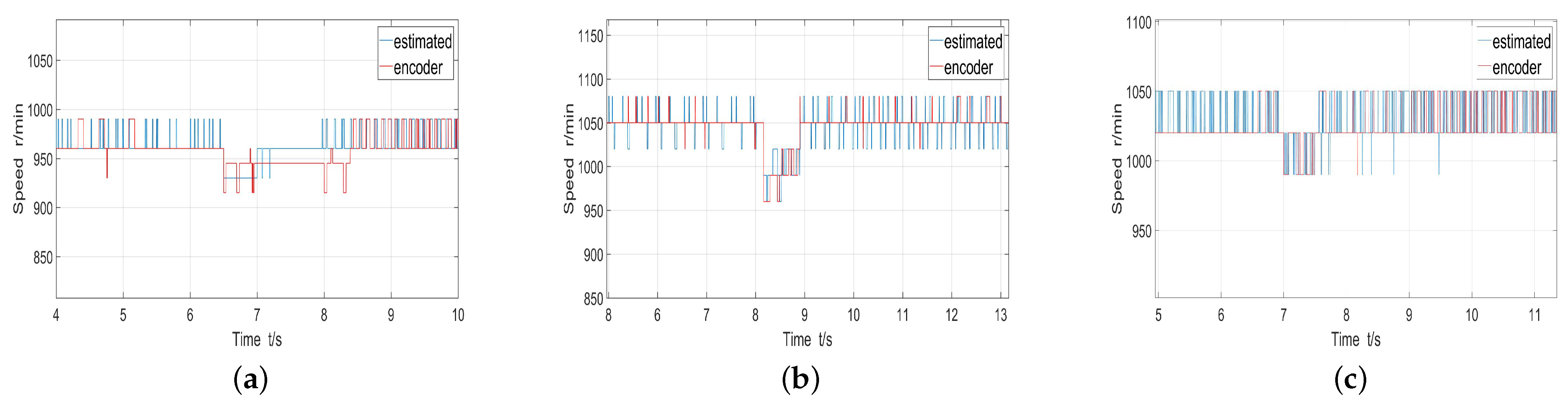
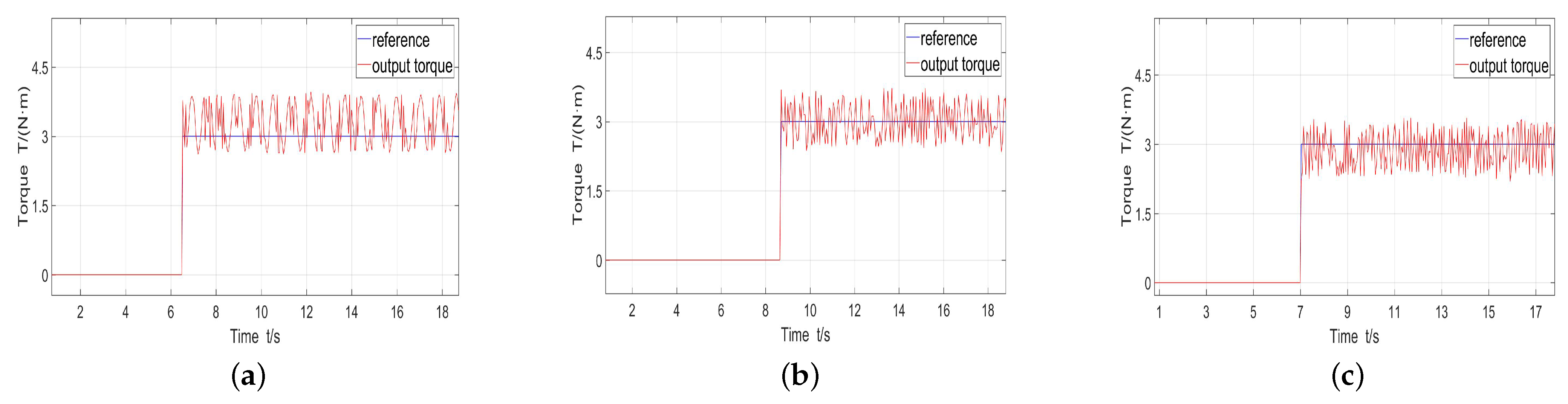
| Traditional | Replicated | Improved | |
|---|---|---|---|
| Speed range | 960–990 r/min | 1020–1080 r/min | 1020–1050 r/min |
| Speed drop under 1 N·m | 30 r/min | 60 r/min | 30 r/min |
| Recovery time under 1 N·m | 1.1 s | 0.8 s | 0.6 s |
| q-axis current under 1 N·m | 1.16 ± 0.2 A | 1.5 ± 0.18 A | 1.12 ± 0.16 A |
| Speed drop under 3 N·m | 30 r/min | 60 r/min | 30 r/min |
| Recovery time under 3 N·m | 1.5 s | 0.8 s | 0.6 s |
Disclaimer/Publisher’s Note: The statements, opinions and data contained in all publications are solely those of the individual author(s) and contributor(s) and not of MDPI and/or the editor(s). MDPI and/or the editor(s) disclaim responsibility for any injury to people or property resulting from any ideas, methods, instructions or products referred to in the content. |
© 2023 by the authors. Licensee MDPI, Basel, Switzerland. This article is an open access article distributed under the terms and conditions of the Creative Commons Attribution (CC BY) license (https://creativecommons.org/licenses/by/4.0/).
Share and Cite
Chen, Y.; Li, A.; Li, H.; Yang, X.; Chen, W. Sensorless Control Method for SPMSMs Based on Improved Sliding Mode Reaching Rate. Electronics 2023, 12, 3720. https://doi.org/10.3390/electronics12173720
Chen Y, Li A, Li H, Yang X, Chen W. Sensorless Control Method for SPMSMs Based on Improved Sliding Mode Reaching Rate. Electronics. 2023; 12(17):3720. https://doi.org/10.3390/electronics12173720
Chicago/Turabian StyleChen, Yuepeng, Aiyi Li, Hui Li, Xu Yang, and Wei Chen. 2023. "Sensorless Control Method for SPMSMs Based on Improved Sliding Mode Reaching Rate" Electronics 12, no. 17: 3720. https://doi.org/10.3390/electronics12173720