Article

Design of a Fuel Cell Test System with Fault Identification

College of Energy Engineering, Zhejiang University, Hangzhou 310027, China
*
Author to whom correspondence should be addressed.
Electronics 2023, 12(15), 3365; https://doi.org/10.3390/electronics12153365
Submission received: 22 June 2023 / Revised: 29 July 2023 / Accepted: 1 August 2023 / Published: 7 August 2023
(This article belongs to the Section Electronic Materials)

Abstract

:
With the growing concerns over the energy crisis and environmental pollution, fuel cells have attracted increasing attention. Proton exchange membrane fuel cells (PEMFCs) have promising prospects due to their economic efficiency, low noise, and minimal environmental pollution. However, the existing commercial testing systems for PEMFCs suffer from limited functionalities and lack of scalability. In this study, we propose the design of a testing platform specifically tailored for water-cooled PEMFCs with a power greater than 1 kW. The functionality of the testing platform is verified through static and dynamic testing, demonstrating its compliance with the required standards. Furthermore, a fault diagnosis model for fuel cell stacks is developed based on the back-propagation (BP) neural network, achieving an overall accuracy rate of over 95% for fault classification.

1. Introduction

Proton exchange membrane fuel cells (PEMFCs) [1] possess unique features such as rapid startup at ambient temperatures, high energy conversion efficiency, low noise, zero emissions, and ease of maintenance. Several companies specialize in the development of fuel cell testing systems and testing equipment, offering both individual testing devices and complete solution packages. In recent years, numerous outstanding testing equipment developers have emerged, gradually catching up with their foreign counterparts in terms of technology. Major universities and research institutes mainly focus on control and testing research of smaller-scale power cell stacks in laboratory settings or concentrate on specific characteristic testing studies. Noteworthy companies engaged in the development of fuel cell testing systems include GREENLIGHT from Canada [2], FUELCON from Germany, and ARBIN from the United States, among others. These technology enterprises have dedicated decades to this field, boasting extensive experience, leading-edge technology, and relatively mature products. Model RG200 series fuel cell test platform is a test platform designed for hydrogen-air PEM fuel cell by Dalian (China) Ruige New Energy Technology Co., Ltd., as shown in Figure 1.
The ARBIN-FCTS (fuel cell test system) from ARBIN, USA, is specifically designed for testing various types of fuel cells, as depicted in Figure 2. Professional company testing platforms can achieve precise data collection and prediction. However, they often face challenges such as large size, poor mobility, high cost, and limited scalability.
Kun Huang. et al. [3] focus on the considerations and key parameter indicators for evaluating the catalytic performance of oxygen reduction catalysts using cyclic voltammetry and linear sweep voltammetry methods. Furthermore, the membrane electrode assembly is assembled into a single fuel cell, and a testing scheme for the single cell is proposed. The aim is to provide reference for evaluating the catalytic performance of oxygen reduction catalysts and the performance of single cells using an electrochemical workstation for proton exchange membrane fuel cells.
Xia, Y. et al. [4], based on Siemens S7-200 series PLC and PID (proportional-integral-derivative) technology, control the error range of the inlet relative humidity to below 0.7%. Additionally, considering potential faults such as hydrogen or nitrogen solenoid valve power failures, cooling fan power failures, temperature anomalies, and hydrogen leakage, the hydrogen recovery system and alarm module are introduced. Hui Chen [5] proposes a hydrogen fuel cell testing system based on combined PLC (programmable logic controller) and ECU (engine control unit) control. This system integrates various sensors and actuators to acquire and regulate physical parameters during battery operation, enabling performance testing under different operating conditions. The design process of the system is described in terms of hardware components, system principles, and control procedures. Practical applications demonstrate that this testing system can effectively meet the testing requirements, accurately obtain physical parameters, and possesses broad application prospects. Zhou, S. et al. [6] present a novel fault diagnosis algorithm called WPD-LSTM, which is based on wavelet packet decomposition (WPD) and long short-term memory (LSTM) neural networks. The WPD-LSTM algorithm takes sensor signals during PEMFC operation as inputs and outputs the fault types of the PEMFC, including normal state or fault sequence numbers for multi-level and multi-layer fault states. Mao, L. et al. [7] propose a novel method for functional evaluation, which assesses feature discriminability and robustness. The proposed method identifies functions that provide accurate and consistent diagnostic performance. Existing features widely used in PEMFC fault diagnosis, extracted from PEMFC voltage or multi-sensor signals, are utilized in this study. The effectiveness of these features in identifying faults in different PEMFC systems is investigated. Jing, L. et al. [8] describe the design of a fuel cell testing system that reintroduces excess hydrogen or oxygen into the fuel cell to improve the utilization efficiency of hydrogen and oxygen. The testing system can also adjust the proportion of moist gas passing through the humidifier and dry gas bypassing the humidifier based on the target humidity and cyclic gas flow, achieving rapid and accurate regulation. Zhenning Liu et al. [9] integrates hydrogen, air, and thermal management control systems into the testing platform, optimizing the layout between subsystems for easier maintenance. The platform utilizes LABVIEW software (2019) for designing the upper computer control interface and Simulink software (2019) for designing the lower-level controller control program and writing the determined component parameters into the controller. Real-time online control of the system through the upper computer control interface is achieved via CAN communication with the controller, allowing automatic optimization of individual component operating parameters based on load changes. Shao, F. et al. [10] construct a modular system design, dividing functions such as hydrogen/air supply, cooling circulation, and electronic load control into modules. Hardware selection for each module is performed, and the control logic of the system is designed with architectural innovations. Fang, M. et al. [11] focus on a high-power fuel cell testing system. The testing system integrates hydrogen circulation and recovery preheating and utilizes a condenser to collect water produced by the stack to achieve integrated gas-thermal utilization. Huang, Z.Y. et al. [12] propose a hardware-in-the-loop (HIL) test bench for testing fuel cell and DC/DC controllers. This test bench consists of a fuel cell simulator implemented in a PC and a DC/DC simulator implemented in a field-programmable gate array (FPGA).
Currently, there are several issues with the fuel cell testing platform.
(1)
The safety measures are not sufficiently robust, such as hydrogen leak detection, over-temperature protection, and current limiting protection.
(2)
The control of parameters such as relative humidity, backpressure, and mass flow rate is not accurate enough or exhibits significant fluctuations.
(3)
The platform lacks fault diagnosis capabilities.
In this paper, we propose a modular design approach to develop a water-cooled proton exchange membrane fuel cell testing platform. The static test demonstrates that the polarization curve acquired by the testing platform aligns well with the polynomial fitting curve. The dynamic test confirms the testing platform’s capability for effective loading and unloading. Additionally, we utilize a BP neural network to create a fault diagnosis model for fuel cell testing stacks, with results indicating that the accuracy of the entire fault classification exceeds 95%.

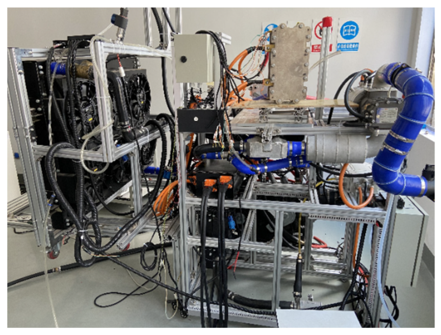
2. PEMFC Testing System Functional Design

The fuel cell testing system [13,14,15,16] needs to ensure the following functionalities:
(1)
Gas supply: The operation of a fuel cell requires a continuous supply of reactants. To ensure the normal operation of the cell, the testing system should stably provide the reactants to the cell.
(2)
Gas parameter control: The parameters of the reactant gases have a significant impact on the performance of the fuel cell. As a tool for researching the performance parameters of fuel cells, the testing system should be able to control various parameters such as the temperature, humidity, and pressure of the reactant gases.
(3)
Cell parameter control: The parameters related to the operation of the cell itself are also a key focus of the testing platform. Typically, it is necessary to control the operating temperature of the fuel cell, and to obtain a complete polarization curve, control over the output voltage and current is also required.
(4)
Safety protection: Safety is a primary concern in any system design. Since hydrogen, one of the reactants, is a flammable and explosive gas, the testing platform should have the capability to detect hydrogen leaks. Additionally, the experimental platform should monitor the operation of all instruments to ensure the normal functioning of the platform.
(5)
Data monitoring function: As a tool for testing fuel cells, the system needs to monitor and provide real-time feedback on various operating parameters, allowing test personnel to monitor the entire system in real-time.
(6)
Data logging function: To alleviate the workload of the test personnel, the testing platform should be capable of automatically and accurately recording experimental data.

2.1. Calculation of Anode and Cathode Reactant Consumption

The anode and cathode gas flow rates are controlled by mass flow controllers to achieve control over the reactant gas flow. The volumetric flow rates of hydrogen and air are represented by Equations (1) and (2), respectively.
V H 2 = 22.42 × 60 I 2 F × n × λ H 2
V A i r = 22.42 × 60 I 4 F ÷ 21 % × n × λ A i r
V H 2 is the hydrogen flow rate. V A i r is the air flow rate. F is the Faraday constant value. I is the current. n is the number of battery cells. λ H 2 and λ A i r are the hydrogen stoichiometric ratio and the air stoichiometric ratio, respectively. Due to the low-temperature and low-pressure nature of the stack system, the requirements for pipeline connections in the entire system are not very high. This paper adopts PU tubing for the connections.

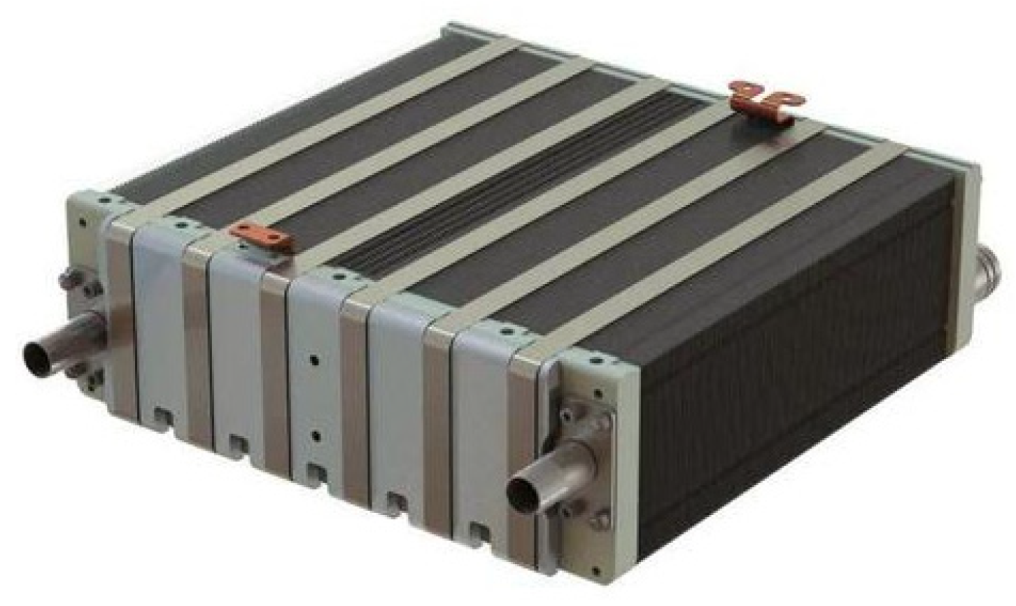
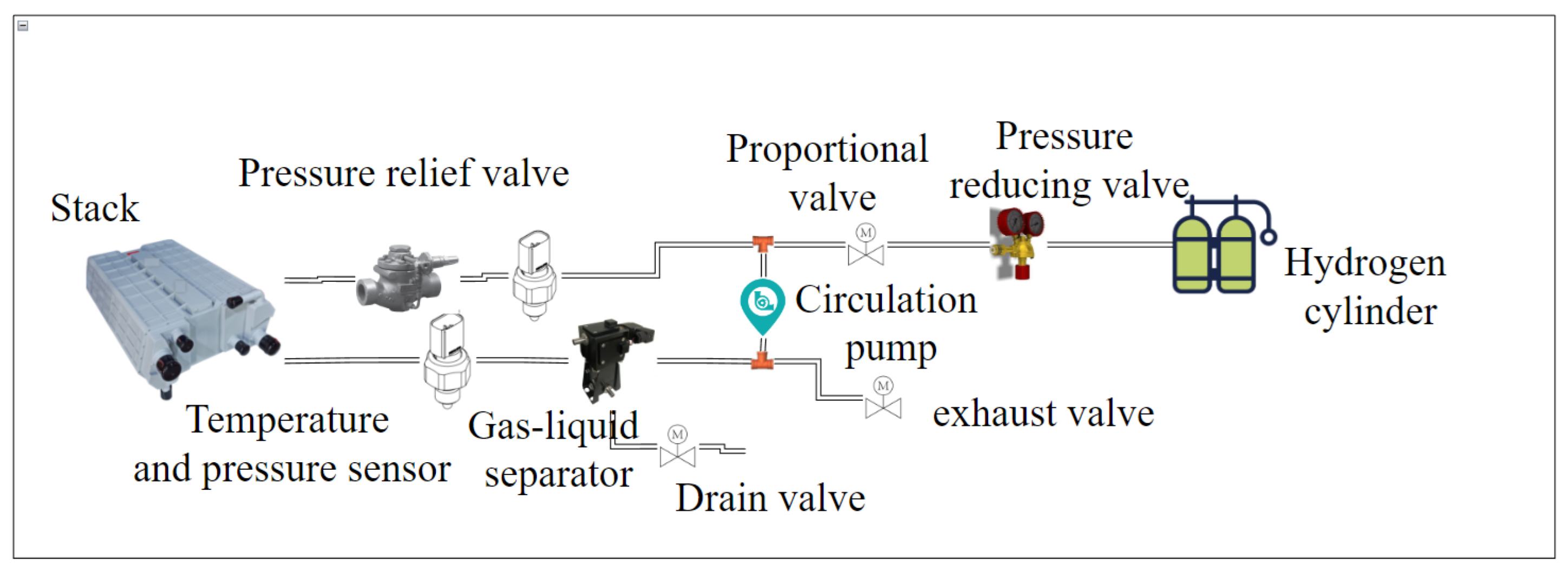
2.2. Hydrogen Supply Subsystem

The hydrogen supply subsystem consists of high-pressure hydrogen cylinders, primary pressure regulators, secondary pressure regulators, flow meters, pressure and temperature sensors, and gas pipelines in Figure 3. Its goal is to provide the fuel cell stack with the appropriate pressure and flow rate of hydrogen. During the operation of a PEMFC, water is generated at the cathode, and most of the water is discharged through the outlet along with the airflow. However, some water may permeate from the cathode to the anode. If the anode does not remove water promptly, it can lead to anode flooding. Additionally, the accumulation of water in the hydrogen circulation can further burden the hydrogen circulation pump or ejector.

2.3. Air Supply Subsystem

The air supply system consists of an air filter, an air compressor, an intercooler, a humidifier, a backpressure valve, and pipeline components in Figure 4. The air filter is used to ensure that impurities are not present in the input to the stack. To improve the efficiency of stack power generation and protect the proton exchange membrane from damage, it is necessary to maintain a stable flow rate and pressure of the cathode air. The flow rate requirement is achieved by the compressor. The pressurized air can reach temperatures of up to 100 °C, but to prevent damage to the stack internals, it is typically cooled down to 50–60 °C using an intercooler. Due to the hydration reaction that occurs during proton transfer in the membrane, it needs to be kept sufficiently moist. Therefore, a humidifier is also installed in the air loop, utilizing the moisture in the cathode exhaust gas for humidification. As water is generated during the cathode reaction, the cathode exhaust gas contains a significant amount of moisture. The fresh air exiting the intercooler is humidified by the water vapor present in the exhaust gas in the humidifier. The pressure of the cathode air is controlled by a backpressure valve, which adjusts the internal pressure by regulating the angle of the blades.

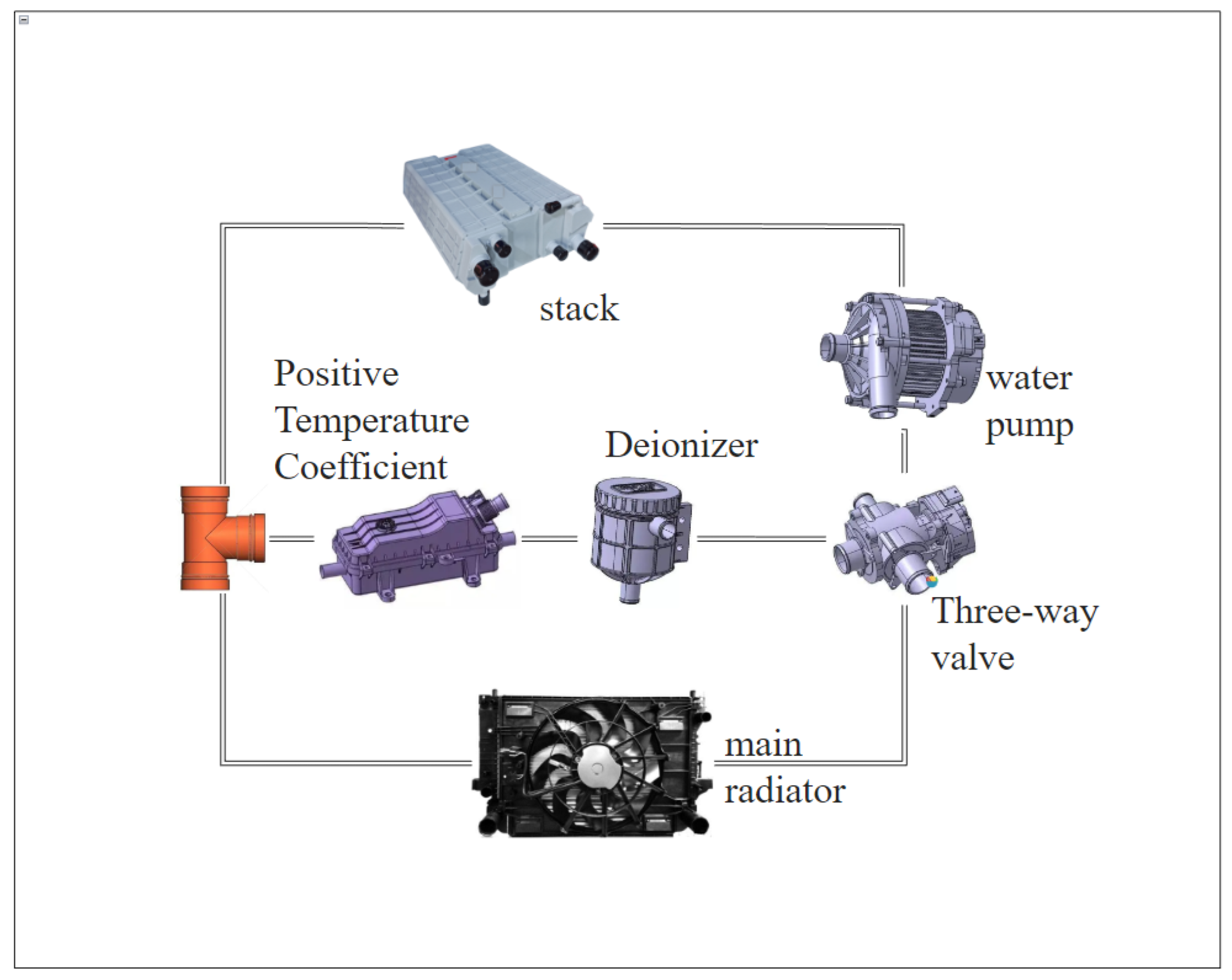
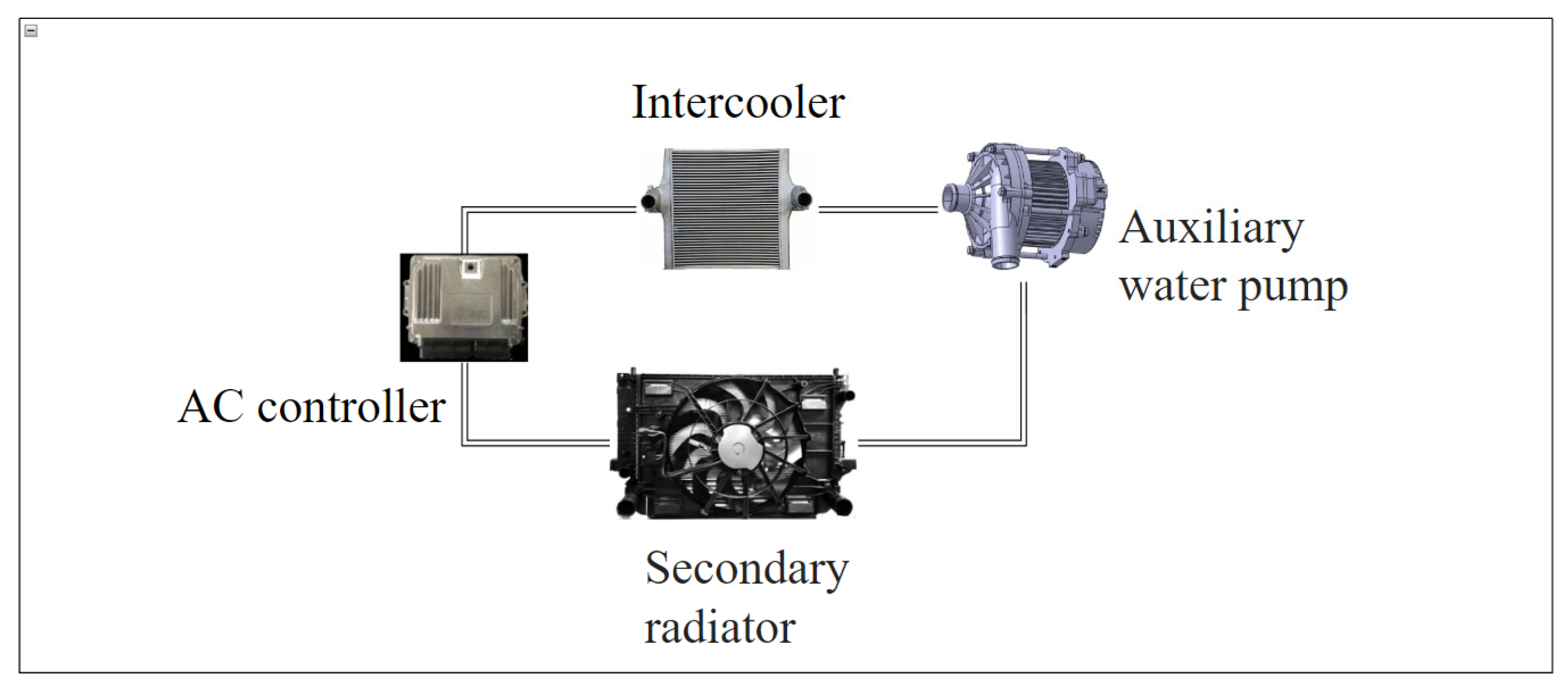
2.4. Thermal Management System-Cooling System

During the operation of the stack, heat is dissipated through circulating cooling water, reaction gases, and radiation to the external environment. Among these, 90% of the heat generated by the stack is carried away by circulating cooling water. A high water tank can control the water level, ensuring that the cooling water unit and the stack are filled with water, and it can automatically replenish water when the water level is too low. When calculating the cooling water flow rate, it is assumed that all heat is carried away by circulating cooling water. The circulating cooling water flow rate depends on the heat dissipation power of the stack and the temperature difference between the incoming and outgoing water, as shown in Equation (3).
V H 2 0 = P × 60 × 1000 ρ H 2 0 × C H 2 0 l × Δ T
ρ H 2 0 is the density of water. C H 2 0 l is the specific heat capacity of water. Δ T is the temperature difference of the cooling water. P is the heat generation power of the stack. V H 2 0 is the flow rate of the cooling water.
Based on the rated power of 10 kW, the fuel cell’s power generation efficiency is generally between 40% and 60%. Therefore, the maximum heat generation power is calculated based on 15 kW. The cooling water temperature entering and exiting the stack is controlled within 5 to 10 °C, and 5 °C is chosen for the calculation. The flow rate is 43 L/min.
The main cooling circuit is shown in Figure 5. The cooling system includes a water pump, three-way valve/thermostat, radiator, deionizer, PTC heater, and radiator. When the water temperature is below 60 °C, the small circulation is activated, and the coolant passes through the deionizer and PTC heater under the drive of the water pump to achieve rapid temperature rise. When the water temperature exceeds 60 °C and cooling is required, the large circulation is activated, and the PTC heater is turned off. The coolant flows through the stack, carrying away the heat from the stack, and dissipates the heat to the air in the radiator. The heat dissipation effect is influenced by two main factors. First, the speed of the water pump determines the flow rate of the coolant. A higher pump speed results in a higher coolant flow rate, leading to a smaller temperature difference and higher consistency in the flow direction of the stack. However, excessive pump speed can increase the parasitic power of the water pump. The second factor is the speed of the fan. The heat dissipation of the coolant mainly relies on the radiator, so the heat transfer capacity of the radiator is also crucial. The thermostat controls the flow rate of the coolant in the large circulation loop based on the coolant temperature.
In addition to the main cooling circuit, as shown in Figure 6, there is also a secondary cooling circuit. The secondary cooling circuit mainly includes an intercooler, an air compressor controller, a secondary water pump, and a secondary radiator.

2.5. Load Subsystem

The fuel cell engine can serve as a power generation system and does not directly output mechanical energy. In practical applications, an electric motor is required to convert the electrical energy into mechanical energy. A power-level load is needed as an output power-consuming device and to provide various operating conditions for the fuel cell engine, simulating the energy flow in a vehicle to some extent. Typical onboard fuel cell power systems need to be equipped with a power battery as a high-voltage power source for accessory systems during startup. As a testing system, considering energy conservation, the electrical energy consumed by the load needs to be fed back to the grid. The overall operational structure and logic are shown in Figure 7.
Fuel cell engines have a lower voltage and current when they are initially started, which is insufficient to drive high-pressure accessories such as the air compressor. At this point, the power battery and DC/DC collaborate to act as a power source to supply power for starting the high-pressure accessories. Once the fuel cell engine is started, it charges the power battery and any remaining electrical energy is regulated and fed back to the grid.

2.6. Other Equipment

Deionized water system: The deionized water system provides deionized water for the heat exchangers that facilitate heat transfer between the cathode and anode gases in the testing platform. Its purpose is twofold: to prevent equipment rust and aging, and to prevent the impurity ions in water from conducting electricity, which could lead to the diffusion of a portion of the power generated by the proton exchange membrane fuel cell to the testing platform’s housing, thereby increasing the risk of electric shock for testing personnel. The use of deionized water effectively prevents such accidents from occurring.

3. Software and Hardware Control System

3.1. Power On/Off Logic

Power-on procedure: When the controller receives a power-on command, it will actively close the auxiliary circuit relay and simultaneously open the relays for the blower, PTC (positive temperature coefficient) element, water pump, and fan. The water pump flow rate is set to the calibrated value, and the water temperature is checked. When the water temperature exceeds 10 °C, the hydrogen supply valve is opened, and the anode flow rate defaults to 12.95 L/min for hydrogen purging. The hydrogen pressure is monitored, and when it exceeds 30 kPa, the air compressor speed is set to the calibrated value (defaulted to 100 L/min). The voltage on both sides of each individual cell is then measured, and if the voltage of single fuel cell exceeds 0.8 V, it indicates normal operation of the fuel cell stack. The main negative relay is closed for high-voltage battery self-diagnosis, followed by the closure of the pre-charge relay for high-voltage system self-diagnosis. Finally, the main positive relay is closed, completing the power-on process. The entire procedure is illustrated in Figure 8.
Power-off procedure: When the controller receives a power-off command, it immediately closes the hydrogen inlet valve and proceeds to simultaneously shut down the air side and cooling system. The air side shutdown is achieved by first turning off the air compressor, followed by disconnecting the main negative relay and main positive relay. The hydrogen inlet valve is then opened for hydrogen purging of the fuel cell stack (purging time: 10 s). After purging, the hydrogen inlet valve is closed. The hydrogen pressure is monitored, and when the pressure is nearly 0, the drain and exhaust valve is closed. An air blowdown is conducted (default blowdown time: 20 s). After completion, the air compressor is turned off. The shutdown process for the cooling system is relatively straightforward: the cooling fan is turned on, and when the cooling water temperature drops below 50 °C, the fan and water pump are turned off. Finally, the auxiliary circuit relay is disconnected, completing the power-off process. The entire procedure is depicted in Figure 9.

3.2. Subordinate Unit

Based on the working principle of proton exchange membrane fuel cells (PEMFCs), a continuous supply of hydrogen and air is required to generate electrical energy. The output voltage of the fuel cell varies with changes in temperature, gas pressure, and gas humidity. Therefore, precise measurements of the fuel cell’s output voltage, current, temperature, gas pressure, and gas humidity are essential in the fuel cell testing system. To facilitate data analysis, it is necessary to record the data from the fuel cell during operation. Additionally, precise control of gas flow rate, gas pressure, gas humidity, fuel cell temperature, and the electronic load that consumes fuel cell power is required.
Considering the real-time nature of data transmission from the subordinate unit and the system’s control speed requirements, as well as the design of the experimental platform itself, the subordinate unit system utilizes the NXP S32K144 chip. This chip is a 32-bit microcontroller based on the Cortex-M3 core, offering high computational performance, timing, digital signal processing, low power consumption, low operating voltage, and integration and ease of development. It features a maximum CPU frequency of 72 MHz, 512 kB flash memory, and various embedded peripherals such as timers, USART (universal synchronous/asynchronous receiver/transmitter), temperature sensors, analog-to-digital converters, and digital-to-analog converters, which can meet various application requirements. Figure 10 illustrates the structure of the subordinate unit system in the testing platform.

4. Proton Exchange Membrane Fuel Cell Experimental Bench Testing

Figure 11 shows the construction of a fuel cell test bench in this paper. After the construction of the testing system, it is necessary to perform an airtightness test on the system. The airtightness test involves pressurizing the system with a certain gas pressure and observing the changes in the pressure gauge’s reading. To identify specific leakage points, a soap bubble test is used. The net rated power output of the entire testing system is 10 kW. Table 1 shows the parameters of the fuel cell for testing.

4.1. Static Polarization Curve

During the load range of 10–100%, the variation range of the fuel cell engine stack output voltage is within 40–49 V, and the output current is within 0–300 A. The variation curves of the fuel cell engine stack output voltage and power with respect to current are shown in Figure 12.
The fuel cell engine consists of 62 individual cells, with an effective area of 255 cm2 per cell. The variation curve of the single cell average voltage with respect to current density is shown in Figure 13. From Figure 13, it can be observed that the experimental data and the polynomial fitting results are consistent, verifying the accuracy and reliability of the test bench system.
From Figure 12 and Figure 13, it can be seen that as the load power increases, the output current of the fuel cell engine increases while the output voltage decreases. Under rated power, the single cell voltage of the fuel cell engine can be maintained above 0.7 V. According to the steady-state efficiency theory, the single cell voltage is an important parameter that affects the conversion efficiency of the cell stack.

4.2. Dynamic Testing

4.2.1. Load Dynamic Response Testing

The dynamic response curves of the fuel cell engine during two load changes are shown in Figure 14 and Figure 15.
From Figure 14 and Figure 15, it can be seen that during the process of loading from idle to 50% rated power, the fuel cell engine stabilizes after 8.1 s and achieves a net output power of 4.9 kW. During the process of loading from idle to 90% rated power, the fuel cell engine stabilizes after 12.1 s and achieves a net output power of 8.8 kW.

4.2.2. Unload Dynamic Response Testing

The dynamic response curves of the fuel cell engine during two load releases are shown in Figure 16 and Figure 17.
From Figure 15 and Figure 16, it can be seen that during the process of unloading from rated power to 50% rated power, the fuel cell engine stabilizes after 5.2 s and achieves a net output power of 4.6 kW. During the process of unloading from rated power to idle, the fuel cell engine stabilizes after 6.6 s at the target power. Based on the results of the dynamic response characteristic tests, it can be concluded that the fuel cell engine has a faster response speed during unloading compared to loading. This is because in the unloading test, the initial power is higher, and the fuel cell engine operates under relatively favorable electrochemical reaction conditions such as temperature and humidity, resulting in a faster response speed.

5. Fault Analysis and Design of Diagnostic Function

This study utilizes a data-driven approach and employs the backpropagation neural network (BPNN) algorithm for fault analysis and identification.

5.1. Fault Simulation Experiment Design

In the experiment, the flooding or membrane drying of the stack is simulated by controlling the proportion of the humidification valve. The high or low temperature fault of the stack is simulated by heating or cooling the environmental chamber. Leakage is simulated by adjusting the opening of the backpressure valve. Blockage is simulated by adjusting the opening of the cut-off.

5.2. Experimental Dataset

Based on the previous section’s mentioned fault simulation experiments, there are a total of seven fault states in the fuel cell system. The data samples for the seven fault states of the fuel cell system were collected through simulated fault experiments. The data collection was repeated five times under the same conditions. After data collection, fault samples were randomly selected from the data collected in the five experiments to form the fault dataset. The fault dataset was divided into a training set and a test set. The training set consists of a total of 21,000 samples, with 3000 samples for each fault type, and the test set consists of a total of 7000 samples, with 1000 samples for each fault type.

5.3. Fault Diagnosis Model Training and Testing

The BP neural network (BPNN), also known as the backpropagation neural network, is composed of neurons and typically consists of three layers: the input layer, hidden layer, and output layer. Activation functions commonly used include linear functions, sigmoid functions, bipolar sigmoid functions, and ramp functions. The main features of BPNNs are forward signal propagation and backward error propagation. In the MATLAB environment, a three-layer BP neural network model with a structure of 17-12-7 was constructed, consisting of 17 input neurons, 7 output neurons, and 12 hidden neurons. The neural network structure is shown in Figure 18.
The hidden layer utilizes a recurrent neural network (RNN) algorithm because it is a neural network structure with recurrent connections, allowing information to persist over time. For time-related fuel cell fault analysis, RNNs can capture dynamic features in time series data, providing more accurate predictions and fault diagnostics. The mean squared error (MSE) loss function is chosen, and the stochastic gradient descent (SGD) optimizer is used to update model parameters to minimize the loss function. Test data are employed to evaluate the performance of the trained and tuned RNN model in fault analysis tasks.
The BP neural network was set with a maximum iteration of 1000 times, a learning rate of 0.1, a training error of 0.00001, and the trainlm training algorithm was selected. The activation functions used were logsig and purelin. Under this training method, Figure 6 represents the training error during the training process, and Table 2 shows the recognition accuracy of different fault states.
From Figure 19, it can be observed that the model’s mean square error reaches the requirement after 137 iterations. From Table 2, it can be seen that the recognition accuracy of the model on the test set exceeds 99%, indicating that the fault diagnosis method based on the BP neural network can diagnose the seven fault states of the fuel cell system and has excellent performance.

6. Summary

Based on extensive research, this paper elaborates on the working principle of fuel cells, the composition of fuel cell testing systems, and the research progress of fuel cell testing systems both domestically and internationally. In this study, a testing platform specifically designed for water-cooled proton exchange membrane fuel cells with a power greater than 1 kW is developed, and static and dynamic tests are conducted. The static test demonstrates that the polarization curve acquired by the testing platform aligns well with the polynomial fitting curve. The dynamic test confirms the testing platform’s capability for effective loading and unloading. Furthermore, a fault diagnosis model for fuel cell testing stacks is developed using BP neural networks, with results indicating that the accuracy of the entire fault classification exceeds 99%.
Based on the findings and accomplishments of this study, there are several potential areas for future work. The current testing platform has demonstrated effective static and dynamic testing capabilities. However, there is room for improvement in terms of performance optimization.
1. Future work will focus on refining the design and operation parameters to enhance the overall efficiency and accuracy of the testing platform.
2. Integrating real-time monitoring and control capabilities into the testing platform can enhance its functionality by enabling continuous assessment of key performance parameters during operation. This would facilitate improved understanding of transient behavior, better control strategies, and early detection of anomalies or faults.
3. As fuel cell technologies continue to advance, it becomes increasingly important to establish standardized testing procedures and protocols. Future research efforts could involve collaborating with relevant industry stakeholders and regulatory bodies to validate the developed testing platform and contribute to the establishment of internationally recognized standards for fuel cell testing.

Author Contributions

Conceptualization, Z.W.; Methodology, S.X., Z.W. and J.C.; Software, S.X., Z.W. and J.C.; Validation, Z.W.; Formal analysis, Z.W.; Investigation, Z.W. and J.C.; Resources, S.X.; Data curation, S.X., Z.W. and J.C.; Writing—original draft, Z.W. and J.C.; Writing—review & editing, Z.W. and J.C.; Visualization, S.X. and J.C.; Supervision, S.X.; Project administration, S.X.; Funding acquisition, S.X. All authors have read and agreed to the published version of the manuscript.

Funding

This research was funded by “The National Key Research and Development Program for New Energy Vehicles in 2022” project (Project Number: 2022YFB2502403) for “Fuel cell passenger vehicle with low-temperature resistance and high safety” and “The 2023 Provincial Cutting-Edge and Leading Talent Research and Development Program” provided funding for “Ultra-Long Endurance Hydrogen-Electric Hybrid Unmanned Aerial Vehicle” project (Project Number: 2023C01239).

Data Availability Statement

The data presented in this study are available on request from the correspond.

Conflicts of Interest

The authors declare no conflict of interest.

References

  1. Jiao, K.; Xuan, J.; Du, Q.; Bao, Z.; Xie, B.; Wang, B.; Zhao, Y.; Fan, L.; Wang, H.; Hou, Z.; et al. Designing the next generation of proton-exchange membrane fuel cells. Nature 2021, 595, 36–369. [Google Scholar] [CrossRef] [PubMed]
  2. Chen, X.; Yang, C.; Sun, Y.; Liu, Q.; Wan, Z.; Kong, X.; Tu, Z.; Wang, X. Water management and structure optimization study of nickel metal foam as flow distributors in proton exchange membrane fuel cell. Appl. Energy 2022, 309, 118448. [Google Scholar] [CrossRef]
  3. Huang, K.; Chen, J.; Mu, Z. Application of Electrochemical Workstation in Proton Exchange Membrane Fuel Cell Testing. Environ. Technol. 2023, 41, 6–12. (In Chinese) [Google Scholar]
  4. Xia, Y.; Lei, H.; Wu, X.; Hu, G.; Pan, H.; Fang, B. Design of New Test System for Proton Exchange Membrane Fuel Cell. Energies 2023, 16, 833. [Google Scholar] [CrossRef]
  5. Chen, H. Design of Hydrogen Fuel Cell Testing System Based on PLC and ECU. Ind. Control Comput. 2022, 35, 21–23+25. (In Chinese) [Google Scholar]
  6. Zhou, S.; Lu, Y.; Bao, D. Fault Diagnosis of PEMFC Systems Based on Wavelet Packet Energy Decomposition and Long Short-Term Memory Neural Network. In Proceedings of the 2022 5th International Conference on Power and Energy Applications (ICPEA), Guangzhou, China, 18–20 November 2022. [Google Scholar]
  7. Mao, L.; Liu, Z.; Low, D.; Pan, W.; He, Q.; Jackson, L.; Wu, Q. Evaluation Method for Feature Selection in Proton Exchange Membrane Fuel Cell Fault Diagnosis. IEEE Trans. Ind. Electron. 2022, 69, 5277–5286. [Google Scholar] [CrossRef]
  8. Jing, L.; Yang, Q.; Liu, Q. Design of test system for hydrogen oxygen fuel cell. In Proceedings of the Hunan Industrial Vocational and Technical College (China); Automotive Engineering Vocational College of Hunan (China), Hohhot, China, 23 November 2022. [Google Scholar]
  9. Liu, Z.; Jiang, K.; Zhao, T.; Fan, W.; Lu, G. Development and Experiment of High-Power Proton Exchange Membrane Fuel Cell Testing System. J. Jilin Univ. (Eng. Ed.) 2022, 52, 2025–2033. (In Chinese) [Google Scholar]
  10. Shao, F.; Kuang, P. Design of Fuel Cell Test System Based on Modularization. In Proceedings of the 2021 3rd International Conference on Artificial Intelligence and Advanced Manufacture, New York, NY, USA, 23–25 October 2022; pp. 678–682. [Google Scholar]
  11. Fang, M.; Cao, J.; Zou, J.; Song, Y. Development and evaluation of an integrated polymer electrolyte membrane fuel cell test system using exergy analysis. Sustain. Energy Fuels 2021, 5, 6157–6169. [Google Scholar] [CrossRef]
  12. Huang, Z.Y.; Zhang, L.Y.; Quan, S.H. Hardware-In-The-Loop Test Bench for Fuel Cell Power System. In Proceedings of the 2015 Chinese Automation Congress (CAC), Wuhan, China, 27–29 November 2015; pp. 1215–1220. [Google Scholar]
  13. Shou, C.; Yan, C.; Chen, J.; Hong, L.; Wu, R.; Luo, Z. Condition Monitoring and Fault Diagnosis of PEMFC Systems. In Proceedings of the 2019 Chinese Automation Congress (CAC), Hangzhou, China, 22–24 November 2019. [Google Scholar]
  14. Zhang, W. Fuel Cell Test System Based on AVR Single-chip Computer. In Proceedings of the International Journal of Advanced Network, Monitoring and Controls, Xi’an, China, 23–25 September 2017; Volume 2, pp. 346–349. [Google Scholar]
  15. Miller, M.; Bazylak, A. A review of polymer electrolyte membrane fuel cell stack testing. J. Power Sources 2011, 196, 601–613. [Google Scholar] [CrossRef]
  16. Shao, M.; Zhu, X.; Cao, H.; Wu, Z. Design and Research of Fuel Cell Testing Experimental Platform. Power Supply Technol. 2017, 41, 994–995+1000. (In Chinese) [Google Scholar]
Figure 1. Fuel cell testing products.
Electronics 12 03365 g001
Figure 2. Typical fuel cell pack.
Electronics 12 03365 g002
Figure 3. Schematic diagram of hydrogen supply subsystem in test system.
Electronics 12 03365 g003
Figure 4. Schematic diagram of the air supply subsystem in the test system.
Electronics 12 03365 g004
Figure 5. Schematic diagram of the main cooling system in the test system.
Electronics 12 03365 g005
Figure 6. Schematic diagram of secondary cooling system in test system.
Electronics 12 03365 g006
Figure 7. Operational structure and logic.
Electronics 12 03365 g007
Figure 8. Power-on procedure.
Electronics 12 03365 g008
Figure 9. Power-off procedure.
Electronics 12 03365 g009
Figure 10. Schematic diagram of test system construction.
Electronics 12 03365 g010
Figure 11. Testing platform.
Electronics 12 03365 g011
Figure 12. Variation curves of fuel cell output voltage and power with respect to current.
Electronics 12 03365 g012
Figure 13. Variation curve of single cell average voltage with respect to current density.
Electronics 12 03365 g013
Figure 14. Dynamic response curve from idle to 50% rated power of the fuel cell.
Electronics 12 03365 g014
Figure 15. Dynamic response curve from idle to 90% rated power of the fuel cell.
Electronics 12 03365 g015
Figure 16. Response curve of rated power from unloaded to 50% of the fuel cell.
Electronics 12 03365 g016
Figure 17. Response curve of rated power from unloaded to idle of the fuel cell.
Electronics 12 03365 g017
Figure 18. Neural network structure diagram.
Electronics 12 03365 g018
Figure 19. Model mean square error.
Electronics 12 03365 g019
Table 1. Parameters of the fuel cell engine.
ProjectParameters
Rated Output Power10 kW
Cooling MethodWater-cooled
Bipolar Plate TypeGraphite
Open Circuit Voltage59 V
Rated Voltage39 V
Rated Current420 A
Single Cell Operating Voltage0.5–0.9 V
Membrane Electrode Area255 cm2
Number of Cells62
Hydrogen Valve Body Diameter21 mm
Air Valve Body Diameter32 mm
Water Valve Body Diameter32 mm
Table 2. Accuracy of fuel cell fault state recognition.
Fault StatusTest SamplesAccuracy
Flooded100099%
Membrane Dry100099%
Low Reaction Temperature1000100%
High Reaction Temperature100099%
Hydrogen Leakage1000100%
Hydrogen Pipeline Blockage1000100%
Air Pipeline Blockage1000100%
Disclaimer/Publisher’s Note: The statements, opinions and data contained in all publications are solely those of the individual author(s) and contributor(s) and not of MDPI and/or the editor(s). MDPI and/or the editor(s) disclaim responsibility for any injury to people or property resulting from any ideas, methods, instructions or products referred to in the content.

