Review

Review of the Legacy and Future of IEC 61850 Protocols Encompassing Substation Automation System

1
Electrical and Computer Engineering Discipline, Curtin University, Perth, WA 6845, Australia
2
School of Engineering and Technology, Central Queensland University, Melbourne, VIC 3000, Australia
3
Centre for Intelligent Systems, Central Queensland University, Brisbane, QLD 4000, Australia
4
Office of the Research & Innovation, Federation University Australia, Ballarat, VIC 3352, Australia
*
Author to whom correspondence should be addressed.
Electronics 2023, 12(15), 3345; https://doi.org/10.3390/electronics12153345
Submission received: 20 June 2023 / Revised: 3 August 2023 / Accepted: 3 August 2023 / Published: 4 August 2023

Abstract

:
Communication protocols play a pivotal role in the substation automation system as they carry critical information related to asset control, automation, protection, and monitoring. Substation legacy protocols run the assets’ bulk data on multiple wires over long distances. These data packets pass through multiple nodes, which makes the identification of the location and type of various malfunctions a challenging and time-consuming task. As downtime of substations is of high importance from a regulatory and compliance point of view, utilities are motivated to revisit the overall scheme and redesign a new system that features flexibility, adaptability, interoperability, and high accuracy. This paper presents a comprehensive review of various legacy protocols and highlights the path forward for a new protocol laid down as per the IEC 61850 standard. The IEC 61850 protocol is expected to be user-friendly, employ fiber optics instead of conventional copper wires, facilitate the application of non-conventional instrument transformers, and connect Ethernet wires to multiple intelligent electronic devices. However, deployment of smart protocols in future substations is not a straightforward process as it requires careful planning, shutdown and foreseeable issues related to interface with proprietary vendor equipment. Along with the technical issues of communication, future smart protocols call for advanced personnel and engineering skills to embrace the new technology.

1. Introduction

Online fault diagnostics and rapid isolation are some of the key features of any Substation Automation System (SAS) that will not only reduce unplanned outages but also improve network reliability. Legacy protocols communicate continuously between the control room and field equipment and act to isolate a faulty feeder or zone when the relevant relay detects a fault by initiating a trip command. All these steps could be validated using a robust communication protocol and by linking the Human Machine Interface (HMI), protection and automation systems, and the primary as well as secondary assets within a substation. In a legacy protocol, the Supervisory Control and Data Acquisition (SCADA) system, Remote Terminal Unit (RTU) and HMI employ Distributed Network (DNP3), MODBUS, PROFIBUS, PROFINET, IEC 618850, and TCP/IP protocols. By using RTUs as the gateway between High-Voltage (HV) field equipment and the central control room, as shown in Figure 1, communications with the field devices have been achieved to date. Regardless of their popularity, legacy protocols have multiple issues, including data breaches, time-consuming diagnostics and cyberattacks [1]. In addition, legacy protocols have issues with slow speeds and complex nodes. In comparison, the recent protocols, such as IEC 61850, possess faster speeds, lesser engineering effort and simple diagnostics that are outlined in the subsequent sections of this paper [2].
Conventional protocols such as DNP3 carry voltage and current data from the substation field to Conventional Instrument Transformers (CITs) using copper cables. CITs are required for the measurement and protection of power system equipment. High-Voltage (HV) CITs are built with an SF6 or oil-filled primary tank. The secondary side of CITs is usually connected to metering and protection devices. However, the data transported over the secondary copper wires are prone to several electro–mechanical faults and complex fault diagnostics, which are very time-consuming [3]. With the introduction of Non-Conventional Instrument Transformers (NCITs) in a digital substation along with additional advanced electronic equipment embedded in the primary and secondary systems, the challenges posed by CITs have been contained to a large extent while providing superior performance with respect to higher resonance, saturation, and bandwidth. The iron core of CITs is one of the main causes of inaccuracy when setting up, which is due to hysteresis losses and saturation. Additionally, CITs experience multiple issues while operating under dynamic loading conditions, which could increase their thermal and mechanical stresses. Moreover, data carried over multiple copper wires slows down the conventional protocol, which makes the automation and protection system unreliable and inconsistent in measurements [4]. Another hazard of conventional-based HV switchyards is related to the oil-filled CITs in the event of a catastrophic failure due to an inadvertent opening of their secondary side, as the saturation of the magnetic core of the Current Transformer (CT) may cause an explosion. This does not happen in NCITs due to the absence of an iron core. These features make NCIT suitable for future power system applications and smart protocols such as IEC 61850 for carrying its digital messages. However, as 99% of the present-day world’s substations are of the conventional type, it is hard to replace all CITs with NCITs without causing disruption to the power grids while transitioning to a new technology [5]. Many utilities and industries have been adapting to Merging Units (MUs), which is a technology that can convert analogue signals of CITs to digital signals.
Based on the IEC 61869 series of standards, which call out CITs or NCITs having analogue or digital output signals, respectively, an appropriate protocol is selected. Rogowski coil has been successfully adopted in gas- or air-insulated substations. This is a kind of NCIT that produces digital output based on Faraday’s law, wherein electrical energy is converted to a digital data packet and transmitted much faster to IEDs leveraging the IEC 61850 protocol, which is another form of Low-Power Stand-Alone Current Sensors (LPSACS). Detailed specifications and performance parameters of LPACS can be found in the IEC 61869-9 guideline [6]. It drastically reduces secondary copper wires and facilitates the use of Fiber Optic (FO) cables. This not only reduces the trench dimension but also enhances power system automation features and the speed of intelligent protection operation. Global research and experimental verifications attest that the introduction of FO and Ethernet cables can enhance the speed of operation of Intelligent Electronic Devices (IEDs) by 30% when compared with the conventional protection system. Table 1 exhibits the benefits of having a digital mode of protection based on a smart protocol [6].
With superior technology and a negligible footprint, NCITs leveraging FOs and process bus technology could potentially eliminate most of the structural, electrical, and mechanical failures currently attributed to the CITs. However, the protocol carrying digital data packets needs extensive validation and performance checks before large-scale deployment.
Analog signals from CIT undergo digital conversion in the form of Sampled Values (SVs) and Generic Object-Oriented Substation Events (GOOSE) data packets. These data packets leverage the IEC 61850 protocol and communicate with IEDs via switches. As defined in the IEC 61850 standard, each digital data packet has a specific task to perform, and the packet size determines the command it represents, such as trip, available, and fault. The data packets circulating GOOSE and SV have encrypted data in multicast mode published to multiple IEDs at a certain time interval and have two dependent factors: measured signal frequency and the Sample Per Period (SPP) dataset. The two SPP values defined in the IEC 61850-9-2 LE standard are 80 and 256 [7]. As an example, if the frequency is 50 Hz and the time interval is 80 ms, the SPP shall be recorded as 1/50/80, which is equivalent to 250 µs. The SV publishes and receives packets within a Local Area Network (LAN). Figure 2 exhibits the overall architecture of a smart protocol interfacing with equipment at process, bay and station bus field devices communicating with IEDs and HMIs at the control room over FO wires [8].

2. Conventional Substation Protocols

Some form of communication protocol is required in the utilities, mining and resource industries for effective communication between field devices and HMIs. Conventional substation protocols have been used for years by industries, but due to the significant increase in renewable energy sources, the green energy revolution and the availability of smarter technologies, conventional protocols that involve multiple copper wires connecting multivendor devices, as shown in Figure 3, are likely to become obsolete soon. As discussed above, such copper wires make fault finding difficult, insecure, and time-consuming. In the case of the CT secondary becoming open, it could lead to CT saturation and catastrophic failure [9].
In addition to the issues of multiple copper wires, conventional protocols have issues with file uploads, data transfers and version upgrades. In a particular conventional switchboard setup, the maintenance team may need to keep the relay functionality in test mode, which poses a danger to personnel as many legacy switchboards are internally non-arc flash-contained. During the protection testing of an energized switchboard, there is a risk of an arc flash event that could pose serious hazards. Additionally, such conventional switchboards have limited capabilities and flexibilities to add more devices or to interrogate the SAS while in operation. Additionally, they could introduce errors due to frequent human interfaces. The following subsections present a deep dive into some advantages and issues associated with conventional protocols. It also narrates the future of smart protocols in conventional and digital substations.

2.1. MODBUS

MODBUS is a data communication protocol that was established in 1979 for use in Programmable Logic Controller (PLC) panels by Schneider Electric. This protocol is primarily used for industrial devices. It is user-friendly with fewer restrictions as compared to other equivalent protocols. It leverages serial, Ethernet, or internet protocols for data exchange from one master device to multiple devices. Automation is achieved by employing RTUs and SCADA systems. Each substation’s relays and peripherals communicate with MODBUS devices, which support radio communication and RS-485, RS-232, or RS-422 serial links. The frames flowing in the network Application Data Unit (ADU) or Protocol Data Unit (PDU) and all other mentioned versions are exhibited in Figure 4 [10].
Some of the standard versions of the MODBUS protocol include MODBUS RTU, ASCII, TCP/IP, UDP, PREMEX MODBUS and MODBUS ENRON. MODBUS operates at different layers, such as the operational level, and it works on response/answer in a serial communication mode. The MODBUS TCP (Transmission Control Protocol)/IP (Internet Protocol) stack provides additional support for conventional MODBUS-enabled devices. Some of the advantages of MODBUS protocols include:
  • Can work in master–slave mode of operation;
  • Can be used by different devices;
  • Ease of adaptability to TCP/IP devices;
  • It moves on raw words and bits, which have very few restrictions;
  • It facilitates a reduction in data errors owing to the least chance of conversion from analogue to digital.
However, there are some limitations to these protocols, such as:
  • It does not have a set standard for defining data objects;
  • It does not provide accurate event occurrence due to the lack of a time stamping log;
  • It is a client–server mode of communication in which data cannot be obtained from an event handler or client by the field device;
  • There is a restriction to the number of devices it can connect to in one data link,
  • Security of the network could be poor, making it easy to compromise data links or intercept data;
  • It has high latency and timing issues;
  • It comprises issues with interoperability using multi-vendor devices.

2.2. PROFIBUS

PROFIBUS, also known as process field bus, was originated in 1989 by the BMBF (German Department of Education and then taken over by Siemens). PROFIBUS is a part of IEC 61158, which was implemented to communicate with field devices using “bit serial” interface mode. Due to legacy issues in communicating with devices, researchers created this protocol that has a common mode of process automation and communication tool. Soon after its implementation, operators discovered issues with the common mode of process communication. It was too difficult to handle and exchange information among themselves. Further research gave rise to PROFIBUS DP (decentralized peripherals). PROFIBUS DP is the most commonly used among the PROFIBUS versions, complemented by PROFIBUS PA (process automation). However, it is observed by the end users that PROFIBUS DP is a faster communication protocol than PROFIBUS PA, which is usually used in hazardous areas. The PROFIBUS PA can be linked to the PROFIBUS DP using linked devices [11].
The advantages of PROFIBUS are as follows:
  • It eliminates the need to have a separate system;
  • Can be used in safety process-related systems;
  • It can be used as hybrid automation;
  • It is compatible with other devices;
  • Its diagnostic is comparatively more user-friendly than other legacy protocols and easy to decipher;
  • It is proactive, and it adapts temporarily to communicate with the previous protocol version.
Some of the limitations of PROFIBUS are:
  • The data transmission rate is around 31.25 kbits/s, which is slow;
  • The speed of data transfer slows down if process parameters fluctuate rapidly;
  • There are shortages of experts in this field, and it is not easy to find subject-matter experts.
There are more than 30 million nodes of PROFIBUS in business, with around 5 million in the process bus industry, without adequate support from technicians and engineers. It must be understood that PROFIBUS and PROFINET are two different protocols and do not have any resemblance in software [12].

2.3. PROFINET

PROFINET, or process field network, is an industry-based field standard that uses Ethernet to communicate and deliver data under restricted time constraints. In this mode of communication, users are supported by the PROFIBUS team in Europe [13].
This protocol follows the IEC 61784-2 standard, which encompasses conformance class A, B, C and D versions of protocols. The PROFINET network includes an IO controller/network/device that works on PLCs to address safety, availability, and security in the processing system. It is a suitable device where redundancy in process automation is required to provide media redundancy with switching times of less than 50 ms. It works well within the High-Speed Seamless Redundancy (HSR) topology. PROFINET has a device driver called PROFI drive that was developed in the 1990s by the PROFIBUS and PROFINET joint venture and covers the simplest to the most complex device drives. Using this drive, users can link up various devices in the process automation network and check the level, temperature, flow rate, valves, and actuators. It uses error and failure mechanisms leveraging consecutive numbering, timeout monitoring, and source and destination authentication. Figure 5 shows the interface of PROFINET devices at different OSI layers, which are broken down into data links and physical layers 1–2 [14]. The network and presentation levels are from 3 to 6 OSI layers, while layer 7 represents the application layer.
PROFINET’s advantages include:
  • It is compatible with PROFIBUS devices;
  • It delivers data on a tight timeline;
  • It provides safety, availability, and security functions to the process.
The limitations of PROFINET versions are as follows:
  • Data exchange is difficult using ethernet wires based on 100-base Tx or 100-base Fx,
  • Extensions and buffer devices are required to establish data exchange among different versions, which creates latency in data transfer,
  • Declining acceptability of PROFINET component base automation since 2014.

2.4. IEC 60870

In order to control and monitor transmission and distribution substation assets, technical committee TC57 suggested the formation of a new standard named IEC 60870, which has about nine parts in a series. Parts 5 and 6 of this relate to teleprotocols and have been widely used. IEC 60870-5 provides a communication profile for sending tele-control messages between two devices. This protocol uses permanently connected data circuits between the two devices [15].
The IEC 60870-6 protocol provides a communication profile between two devices, leveraging tele-control messages between the two systems. This standard is also deployed to connect multiple substations spread over long distances from a centralized control room to optimize the use of various resources [16].
Some of the major gains of this standard include:
  • It provides spontaneous and cyclic data updating schemes;
  • It facilitates proper time synchronization;
  • Data are classified into different objects that are provided with different addresses;
  • It supports balanced and unbalanced modes of data transfer. However, the shortcomings of this protocol include:
  • It does not provide encryption;
  • Interoperability is still a question mark, as it may not be compatible with other devices;
  • It is limited to communication among devices within the substation;
  • It declines expertise and support base in solving issues arising when interfaced with new equipment.

2.5. DNP3

DNP3 is one of the most popular communication protocols used by utilities in the SCADA system and was developed in 1993 by GE-Harris in Canada [17]. It is a widely accepted protocol in various applications that employ secondary copper cables to transmit voltage and current signals.
Some of the major advantages of this protocol include:
  • It facilitates interoperability among devices manufactured by other vendors;
  • It provides a reduction in bit mapping;
  • It offers reliable communication to and from field devices;
  • It overcomes distortion emanating from electromagnetic induction;
  • It provides error checking, link control and prioritization;
  • It provides time synchronization;
  • It has a flexible bandwidth and reduces noise while transmitting data compared to other protocols;
  • It is more robust and reliable than NODBUS, PROFIBUS and PROFINET;
  • It provides time-stamped data;
  • It has the ability to provide data in multiple formats, i.e., 12-bit, 16-bit and 32-bit, with or without a flag;
  • It is compatible with IEC 60870-5.
On the flip side, DNP3 users have experienced a few disadvantages, as listed below:
  • Complexity in diagnostics and fault finding in the network;
  • Some new devices do not operate well with this protocol;
  • Field equipment encompassing complex secondary wiring makes troubleshooting difficult;
  • Messy copper wires make fault diagnostics look complicated;
  • It works mostly with low bandwidth;
  • Its wiring scheme is difficult to handle in the event of troubleshooting;
  • Commissioning requires much preparation and planning. The wrong set-up could lead to delays in deciphering the fault and commissioning the system.
Figure 6 exhibits a master layer on the left-hand side that initiates a data transfer lever on the application layer. The outstation layer on the right-hand side is installed with a data link layer that receives octets from the physical layer and scans them for errors. All error-free octets are then passed on to the application layer within the outstation layer. The outstation layer further transmits the octet back to the master layer to close the loop [18].

2.6. TCP/IP

Invented in 1978, TCP/IP stands for Transmission Control Protocol (TCP) and Internet Protocol (IP). This protocol has been used until today in many utilities and industries. It bundles all data packets using a user-friendly language and a code that computers speak and understand [19].
In this protocol, the information contained within the data packet determines its routing path. The IP section of a packet focuses on logistics and guides the packet to its destination like a driver, who operates and guides a vehicle to its destination from point A to point B. On the other hand, TCP checks for errors in the packet, and if any are detected, it retransmits the packet [20].
Some of the commonly addressed TCP/IP protocols in today’s industries and utilities relate to HTTP, HTTPS, and FTP. In this protocol, there are four different layers: the Network Access layer, the Internet layer, the Transport layer, and the Application layer [21].
Advantages of the TCP/IP protocol include:
  • It can be used on all types of computers using TCP/IP addresses, such as static, dynamic and IP v6.
  • It is widely used in utility substations and industries with available vendor support;
  • This technology is still supported by many vendors on their le.acy devices. However, it comprises a few issues:
  • It is not easy to remember the nomenclatures and number tags (e.g., Google uses 216.58.216.164 for computers at the workplace, and one does not have a clue about the numbers that it uses in its strings);
  • High cost to install, configure and maintain;
  • Difficult to maintain and connect to devices after a version upgrade;
  • Cannot capture all dynamic or changing data packets in a computer system;
  • TCP/IP data transmission is carried over by multiple data packets in the network. There is a possibility of nuisance trips due to errors;
  • Vulnerability of data packets due to cyber threats and insecure modes of transportation.
The TCP/IP protocol has a lot of common features with the Operating System (OS) model. These two are the most widely used communication and networking protocols.
In summary, legacy protocols have a number of disadvantages, as enumerated above, which could be addressed more accurately by leveraging the IEC 61850 protocol as per the following subsection.

2.7. IEC61850

Communications using smart protocol technology have improved by leaps and bounds, and with the shift towards digital automation in infrastructure, mining, renewables and resource sectors, the International Electronic Commission (IEC) tasked the TC 57 group in 2002 to provide a guideline that enables engineering processes related to electrical power systems to become simpler and reduce labor. Today, the standards related to IEC 61850 have grown to 60 parts, with further expansion to condition monitoring and asset management [22]. This protocol addresses a number of issues that besieged conventional protocols, including but not limited to:
  • Faster and more reliable protection;
  • A reduction in copper wires due to the use of FO and Ethernet technology can save the project cost and ease diagnostics in the event of a fault;
  • Adaptability over TCP/IP and communication with conventional protocols and LANs using Manufacturing Message Specification (MMS), GOOSE, and Sampled Measure Values (SMV);
  • Swift data transfer of events.
IEC 61850 has a series of standards that touch every aspect of utilities and industries’ electrical networks. Figure 7 shows a substation architecture encompassing three tiers, i.e., Station bus, Bay level and Process bus [23,24]. In the station bus architecture, the IEDs communicate horizontally, while in the Process bus architecture, field devices communicate with IEDs through network peripherals such as switches, Redboxes, routers, and RTUs [25].
A number of standards have been linked with the IEC 61850 series, and their relevance can be summarized as shown in Figure 8 in various parts [26].
In recent transmission substation projects undertaken by ALSTOM (in Australia and the USA), a cost–benefit analysis indicates that an approximately 20% reduction in the project cost leveraging process bus topology has been achieved. In summary, the construction of a digital substation has a faster delivery time and reduces periodic maintenance. One of Transgrid’s switching substations in New South Wales, Australia, returned 25% savings to the utility operator, encompassing intelligent switchgear, and digital protection cabinets, lesser control cabling, and reduced engineering efforts [27,28].
Installation of digital equipment at the primary and secondary systems provides a huge reduction in copper wire when shifting from conventional to digital, as exhibited in Figure 9a,b. These two figures exhibit the reduction of complexity not only with wiring but also with fault diagnostics and termination point wiring. Moving away from copper wires has the following benefits:
-
Ease of fault diagnostics;
-
Mitigation of arc flash leveraged FO wires;
-
Reduced fire hazards as FO wires do not propagate fire;
-
Lesser hazard while standing in front of non-arc-contained switchgear performing protection;
-
Lesser engineering and designing efforts reduce the man-hours needed to complete the project.
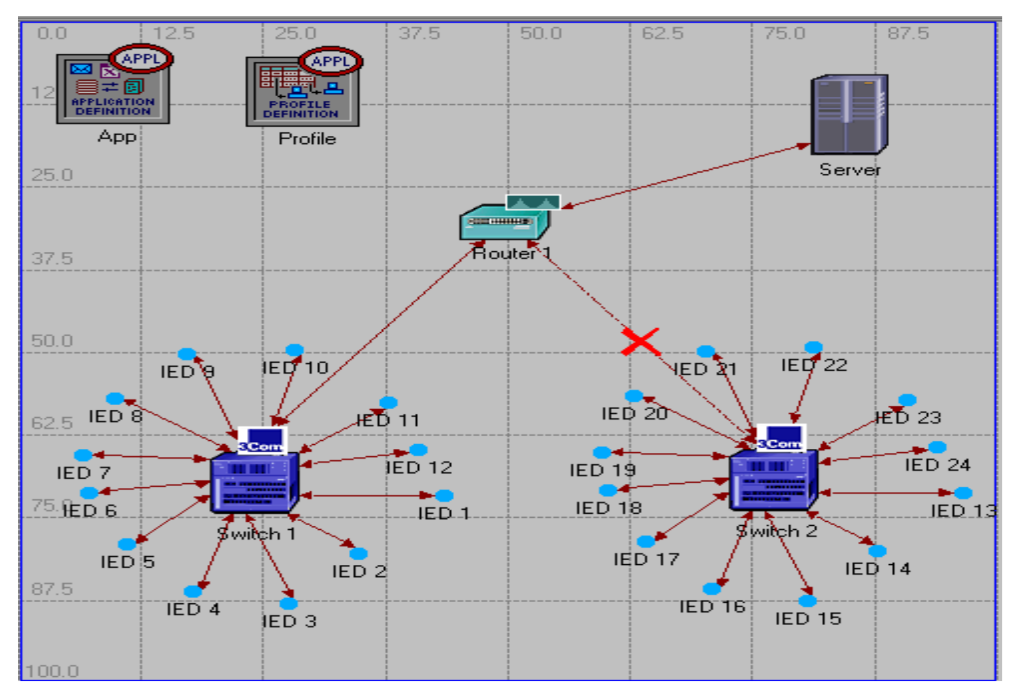
There are three layers of SAS in IEC 61850 standards, encompassing process, bay, and station bus levels within a utility substation [28]. Table 2 details the communication and data exchange architecture among primary plants, secondary equipment, and all the way up to the control and command center [29].
The IEC 61850-9-2 guideline gives the time synchronization and speed of data packet circulation in SAS networks, as per Table 3 [30]. Digital data packets running on this protocol travel at a predetermined speed to get identified either as a fault, control or measurement task as applicable to digital data transmission and subscription in a SAS network [31].
Message transmission time is governed by the speed, traffic, and number of nodes via which the digital data packet travels. MU converts analogue current and voltage signals of CITs to digital data packets such as GOOSE and SV. These digital packets broadcast in the network to connected IEDs passing via managed switches in a SAS network. Detailed guidelines on process bus topology have been summarized in the IEC 61850-5 standard, which stipulates MU devices shall have an accuracy of ±4 µs in a communication network with no more than a 2-microsecond delay. MUs transmit these data packets further to IEDs for processing [32]. The introduction of MU not only reduces the secondary cabling effort to a significant level but also reduces maintenance downtime, besides passing over the cost benefits to the project [33].
Figure 10 exhibits the working principle of MU, which receives several inputs from CITs [34]. The MU converts the analogue signals into digital signals that are transmitted to IEDs via a managed switch over FO or Ethernet cables. Substitution of NCITs in place of CITs could offer high accuracy and data acquisition using SVs. The advantages of NCITs over CITs include their immunity to saturation due to the absence of a magnetic iron core and their insensitivity to thermal and mechanical stresses. Moreover, it is environmentally friendly, as there is no requirement to fill NCIT with SF6 or insulating oil. Additionally, there is a reduced civil and structural footprint of the plant using NCITs [32]. NCITs have reduced errors as opposed to CITs, which are vital for automation, protection and relaying in a SAS environment. However, in order to make it widely acceptable in the industry, all scenarios need to be modelled and experimented in a laboratory environment first [35].
Figure 11 exhibits a test setup for an IEC 61850 experiment at the Curtin University IEC 61850 laboratory. The test equipment in the figure helps to simulate fault conditions and measure the DC offset values. The performance results of an 11-kilovolt NCIT were compared with those of a similar-rated CIT for fault and DC offset conditions. The NCIT equipment chosen for this test at an 11-kilovolt voltage level has a peak fault withstand capability of 63 kA for 1 s, Class 5P. The overall performance using process bus technology showed the superiority of digital over conventional technology, leveraging the IEC 61850 protocol [36].
The Wireshark tool is used to capture the SV and GOOSE floating in the network. Figure 12 shows a snippet of a screen dump that identifies an SV packet floating in the network with the signature of the devices having the tag AA1JQO2A2. This packet is subscribed to by the IED Micom P541. Figure 13 is a screenshot of the SV stream in the network captured using the SV Scout tool of Omicronenergy.
Figure 14 shows an ABB make PCM 600 tool that configures ABB make SMU 615. In this Figure, to-and-from fields have been identified in order to send the target to its destination.

3. OPNET Tool

The modelling of a digital network is of paramount interest to researchers. Although there are multiple tools available to capture and analyze digital data, Operational Network Technology (OPNET) has been accepted as a standard tool that verifies mean delay, average delay, traffic lost, latency, End-to-End (ETE) delays and traffic load in the network while passing through various loads. OPNET has been built with the following base [37]:
  • Parameter editor
  • Process editor
  • Node editor
  • Project editor
In a SAS network, the preferred data communication rate is usually set at 100 Mb/s with a sampling frequency of 4800 Hz. GOOSE messages are slower than SV packets due to multiple nodes at switches and IEDs. The losses encountered in the SV packets are negligible in the network as opposed to the GOOSE packets. To summarize, ETE and latency to IEDs have been streamlined within the standard as stipulated by the IEC 61850-9-2 guideline to below 4 µs when tested with a LAN speed of 100 Mbps and a sampling rate of 4800 sample/s. Hence, the SV method of data transmission used in process buses has a better chance of succeeding in future SAS networks [38].
OPNET modelling can analyze almost all scenarios in data transmission and subscription exhibiting traffic queuing, End-To-End (ETE) delay and average delay. It also provides an accurate estimation of a real-life digital SAS scenario involving routers, switches, and IEDs. Figure 15 exhibits typical modelling of a tree network using the OPNET library that comprises switches and various IEDs. In this model, the IEDs are connected in a star topology to two switches. By running the application, one could estimate the ETE and average delays.

4. Discussion

Conventional substation protocols exhibit issues with expansion, version upgrades and data transfer due to changes in the software and the availability, accuracy, and reliability of the data. These issues have been addressed in the IEC 61850 protocol, which provides flexibility in monitoring, automation and optimization in operation. For example, IEC 60870-5 usually communicates via SCADA in a master–slave mode within an electrical substation for the control and acquisition of data on serial lines or TPC/IP between power centers over WAN networks, which slows down the communication when the transferred data are large. This is not the case when dealing with IEC 61850 [39]. IEC 61850 is a standard published by the IEC technical group TC 57 that could encompass the protection, measurement, control, automation and condition monitoring of substation assets.
Some review papers on conventional and digital communication protocols have been published in the literatures. However, most of these papers did not provide clear guidance in migrating towards digital protocols for future smart grids. For instance, Ref [40] presents a review on IEC 61850 and communication protocols in substation automation systems. However, the paper ignored some important substation protocols such as Profibus, Profinet and TCP/IP protocols. Moreover, a comprehensive comparison among reviewed protocols has not been presented in the paper. It is worth to mention that Profibus, Profinet and TCP/IP protocols are currently in operation at many substations globally.
This review paper presents a comprehensive review on conventional communication protocols and provides further commentary on Modbus, Profibus, Profinet, IEC60870, DNP3, and TCP/IP. These legacy protocols have been compared to digital protocol based on IEC 61850 guideline with practical configurations, and OPNET models with some experimental results. The paper also highlights the application of non-conventional instrument transformers in future substation automation systems.
As a quick guideline of moving forward into full substation automation systems, Table 4 presents a comprehensive comparison between all legacy (conventional) protocols and the IEC61850 future digital protocol. Also, Table 5 summarises the main issues of legacy protocols and how these issues can be addresses by adopting IEC 61850.

5. Conclusions

Legacy protocols in utilities and industrial substations traditionally include MODBUS, PROFIBUS, PROFINET, IEC 80870, DNP3 and TCP/IP. Over the past 50 years, operators have experienced multiple issues such as slow client/server data exchange and non-communication between multi-vendor equipment, i.e., interoperability issues. Compounding these problems is dealing with massive bundles of copper wire that make fault diagnostics a nightmare. On the other hand, smart protocols such as the IEC 61850 protocol significantly reduce engineering effort and cost and provides an improved topology architecture by using Ethernet and FO cables. The introduction of this smart protocol augurs well for the business, as it allows a smooth flow of digital data packets that enhance reliability in automation technology within multivendor equipment in substations. In comparison to legacy protocols, smart protocols promise to provide a host of benefits, such as asset management of plants, condition monitoring of critical assets and ease of maintenance. It reduces project costs by 20–30% and provides superior performance from a SAS perspective. Process bus technology, as enumerated in the IEC 61850-9-2 standard, seems to be the future of smart digital substation communication with a range of options while interfacing with HV and LV equipment. However, there are some limitations to IEC61850, as witnessed in the industry. This includes the gap in knowledge and the resistance of many engineers to adapting to this new technology. Adopting digital technology will also bring a big risk of cyberattacks and threats to network security. This calls for further research related to the IEC 61850 protocol to attest to its large-scale deployment on future power grids.

Author Contributions

S.K. conducted the experimental testing at the Curtin University IEC 61850 laboratory and drafted the first version of this paper under the supervision of A.A.-S., N.D. and S.I., who analyzed the obtained results, checked, reviewed and edited the final version of this paper. All authors have read and agreed to the published version of the manuscript.

Funding

This research received no external funding.

Data Availability Statement

Data sharing is not applicable to this article.

Acknowledgments

The authors would like to gratefully acknowledge the support provided by ABB, GE, Siemens, Schneider, SEL, and Omicronenergy Australia for their support and contribution in terms of tools and protocol devices, highlighting the opportunity that could be undertaken to implement the IEC 61850 protocol in the industry by researching at the Curtin University IEC61850 Laboratory.

Conflicts of Interest

The authors declare no conflict of interest.

References

  1. Chen, G.Y.; Newson, T.P. Detection of fibre-optic current sensors based on faraday effect. IET J. Mag. 2014, 50, 626–627. [Google Scholar]
  2. Sidhu, T.S.; Yin, Y. Modelling and simulation performance evaluation of IEC 61850 based substation communication system. IEEE Trans. Power Deliv. 2007, 22, 1482–1489. [Google Scholar] [CrossRef]
  3. Vita, V.; Fotis, G.; Pavlatos, C.; Mladenov, V. A New Restoration Strategy in Microgrids after a Blackout with Priority in Critical Loads. Sustainability 2023, 15, 1974. [Google Scholar] [CrossRef]
  4. Vita, V.; Fotis, G.; Chobanov, V.; Pavlatos, C.; Mladenov, V. Predictive Maintenance for Distribution System Operators in Increasing Transformers’ Reliability. Electronics 2023, 12, 1356. [Google Scholar] [CrossRef]
  5. Burgund, D.; Nikolovski, S. Comparison of Functionality of Non-Conventional Instrument Transformers and Conventional Current Transformers in Distribution Networks. In Proceedings of the 2022 International Conference on Smart Systems and Technologies (SST), Osijek, Croatia, 19–21 October 2022; pp. 55–60. [Google Scholar] [CrossRef]
  6. Schaub, P.; Haywood, J.; Ingram, D.; Kenwrick, A.; Dusha, G. Test and Evaluation of Non-Conventional Instrument Transformers and Sampled Value Process bus on Powerlink’s Transmission network. In Proceedings of the 2011 South East Asia Protection and Control Conference (SEAPAC 2011), Sydney, Australia, 9–11 March 2011. [Google Scholar]
  7. Moreno, A.; Gil, C.; Santiago, J.R. IEC 61869–10 and IEC 61869–11 Passive Sensors and their Interface with IEDS. In Proceedings of the CIRED 2021—The 26th International Conference and Exhibition on Electricity Distribution, Online Conference, 20–23 September 2021; pp. 440–443. [Google Scholar] [CrossRef]
  8. Schmid, J.; Schumarcher, M. IEC 61850 Merging Unit for the universal connection of conventional and Non-Conventional Instrument Transformers. In Proceedings of the CIGRE, AS-306, Paris, France, 24–29 August 2008. [Google Scholar]
  9. Liu, K.; Dong, X.; Bo, Z. Current differential protection based on non-conventional instrument transformer and IEC 61850. In Proceedings of the 43rd Universities Power Engineering Conference 2008 (UPEC 2008), Padova, Italy, 1–4 September 2008. [Google Scholar]
  10. Hinkley, K.; Batger, D. Transgrid’s journey to a full digital substation. In Proceedings of the SEAPAC 17-APB5, Melbourne, Australia, 14–15 September 2017. [Google Scholar]
  11. Tamboli, S.; Rawale, M.; Thoraiet, R.; Agashe, S. Implementation of Modbus RTU and Modbus TCP communication using Siemens S7-1200 PLC for batch process. In Proceedings of the 2015 International Conference on Smart Technologies and Management for Computing, Communication, Controls, Energy and Materials (ICSTM), Avadi, India, 6–8 May 2015; pp. 258–263. [Google Scholar] [CrossRef]
  12. Chen, J.; Li, L.; Wang, L. The Application of PROFIBUS Technology in the Fengchan River Project’s Electronic Control System Reform. In Proceedings of the 2012 Fifth International Conference on Intelligent Networks and Intelligent Systems, Tianjin, China, 1–3 November 2012; pp. 130–133. [Google Scholar] [CrossRef]
  13. Bao, W.; Zhang, H.; Li, H.; Huang, W.; Peng, D. Analysis and Research on the Real-Time Performance of Profibus Fieldbus. In Proceedings of the 2009 WRI World Congress on Software Engineering, Xiamen, China, 19–21 May 2009; pp. 136–140. [Google Scholar] [CrossRef]
  14. Wu, X.; Xie, L. On the Wireless Extension of PROFINET Networks. In Proceedings of the 2019 IEEE VTS Asia Pacific Wireless Communications Symposium (APWCS), Singapore, 28–30 August 2019; pp. 1–5. [Google Scholar] [CrossRef]
  15. Yang, M.; Li, G. Analysis of PROFINET IO Communication Protocol. In Proceedings of the 2014 Fourth International Conference on Instrumentation and Measurement, Computer, Communication and Control, Harbin, China, 18–20 September 2014; pp. 945–949. [Google Scholar] [CrossRef]
  16. Belousov, A.V.; Koshlich, Y.A.; Bashkatov, I.V.; Grebenik, A.G. Investigation of communication standard IEC 60870 used to create substations remote control systems. In Proceedings of the 2017 IEEE 58th International Scientific Conference on Power and Electrical Engineering of Riga Technical University (RTUCON), Riga, Latvia, 12–13 October 2017; pp. 1–4. [Google Scholar]
  17. Sharma, S.; Kumar, V.; Sharma, P.; Gupta, S.; Shukla, A. SCADA Communication Protocols: Modbus & IEC 60870–5. In Proceedings of the 2022 1st International Conference on Sustainable Technology for Power and Energy Systems (STPES), Srinagar, India, 4–8 July 2022; pp. 1–6. [Google Scholar] [CrossRef]
  18. Amoah, R.; Camtepe, S.; Foo, E. Securing DNP3 Broadcast Communications in SCADA Systems. IEEE Trans. Ind. Inform. 2016, 12, 1474–1485. [Google Scholar] [CrossRef] [Green Version]
  19. Bagaria, S.; Prabhakar, S.B.; Saquib, Z. Flexi-DNP3: Flexible distributed network protocol version 3 (DNP3) for SCADA security. In Proceedings of the 2011 International Conference on Recent Trends in Information Systems, Kolkata, India, 21–23 December 2011; pp. 293–296. [Google Scholar] [CrossRef]
  20. Skrastins, A.; Jelinski, J.; Lauks, G. Evaluation of new approach for fair downlink bandwidth distribution in TCP/IP networks. In Proceedings of the IET International Conference on Information and Communications Technologies (IETICT 2013), Beijing, China, 27–29 April 2013; pp. 117–123. [Google Scholar] [CrossRef]
  21. Liao, R.K.; Ji, Y.-F.; Li, H. Optimized Design and Implementation of TCP/IP Software Architecture Based on Embedded System. In Proceedings of the 2006 International Conference on Machine Learning and Cybernetics, Dalian, China, 13–16 August 2006; pp. 590–594. [Google Scholar] [CrossRef]
  22. Wei, A.; Chen, Y.; Wu, J. Simulation Study of TCP/IP Communication Based on Networked Control Systems. In Proceedings of the 2006 6th World Congress on Intelligent Control and Automation, Dalian, China, 21–23 June 2006; pp. 4479–4483. [Google Scholar] [CrossRef]
  23. OPNET Modeler—OPNET Technologies. Available online: http://www.opnet.com (accessed on 1 April 2023).
  24. Hughes, R. Considering the process bus. In Proceedings of the SEAPAC, Cigre Australia Panel B5, Melbourne, Australia, 17–18 March 2009. [Google Scholar]
  25. Igarashi, G.; Santos, J.C.; Junior, S.N.; Pellini, E.L. Development of a digital optical instrument transformer with process bus interface according to IEC 61850-9-2 standard. In Proceedings of the 2015 IEEE PES Innovative Smart Grid Technologies Latin America (ISGT LATAM), Montevideo, Uruguay, 5–7 October 2015; pp. 893–897. [Google Scholar]
  26. Raujo, J.A.A.; Lazaro, J.; Astaloa, A.; Zuloaga, A.; Garcia, A. PRP and HSR Version 1 (IEC 62439-3 Ed.2) Improvements and a Prototype implementation. In Proceedings of the 2013 Industrial Electronics Society, IECON 2013, Vienna, Austria, 10–13 November 2013. [Google Scholar] [CrossRef]
  27. Kumar, S.; Das, N.; Islam, S. Causes and mitigation of sympathetic tripping phenomenon based on IEC 61850. In Proceedings of the Australian Protection Symposium 2014, Sydney, Australia, 12–13 August 2014. [Google Scholar]
  28. Kovic, L.J. Innovative Non-convention Current Transformer for advanced Substation design and improved Substation performance, Paper A3-208. In Proceedings of the 42nd CIGRE Session 2008, Paris, France, 24–29 August 2008. [Google Scholar]
  29. Hou, D.; Dolezilek, D. IEC 61850—What it can and Cannot offer to Traditional Protektion Schemes. SEL J. Reliab. Power 2010, 1, 6335. [Google Scholar]
  30. IEC 61850-9-2 2004; Communication Networks and Systems in Substations—Part 9-2: Specific Communication System Mapping (SCSM)—Sampled Values over ISO/IEC 802-3. 1st ed. ICT Standards for Procurement: Brussels, Belgium, 2005.
  31. IEC 61850-9-2 LE; Implementation Guideline for Digital Interface to Instrument Transformers Using IEC 61850-9-2. UCA International Users Group: Shell Knob, MO, USA, 2012.
  32. Apostolov, A.; Auperrin, F.; Passet, R.; Guenego, M.; Gilles, F. IEC 61850 process bus based distributed waveform recording. In Proceedings of the Power Engineering Society General Meeting, Montreal, QC, Canada, 18–22 June 2006. [Google Scholar]
  33. Kumar, S.; Abu-Siada, A.; Das, N.; Islam, S. Reverse Blocking Over Current Busbar Protection Scheme Based on IEC 61850 Architecture. IEEE Trans. Ind. Appl. 2023, 59, 2225–2233. [Google Scholar] [CrossRef]
  34. Kumar, S.; Abu-Siada, A.; Das, N.; Islam, S. Toward a Substation Automation System based on IEC 61850. Electronics 2021, 10, 310. [Google Scholar] [CrossRef]
  35. Kumar, S.; Abu-Siada, A.; Das, N.; Islam, S. Comparison between Wired versus Wireless Mode of Digital Protection Scheme Leveraging on PRP Topology. In Proceedings of the 2022 IEEE Sustainable Power and Energy Conference (iSPEC), Perth, Australia, 4–7 December 2022; pp. 1–5. [Google Scholar] [CrossRef]
  36. Kumar, S.; Abu-Siada, A.; Das, N.; Islam, S. A Fast and Reliable Blocked Bus Bar Protection Scheme Leveraging on Sampled Value and GOOSE Protection based on IEC 61850 Architecture. In Proceedings of the Australasian Universities Power Engineering Conference (AUPEC), Perth, Australia, 26–30 September 2021; pp. 1–5. [Google Scholar]
  37. Kumar, S.; Das, N.; Islam, S.; Abu-Siada, A. Verification of Latency and Delays Related to a Digital Topology based on IEC 61850. In Proceedings of the 29th Australasian Universities Power Engineering Conference (AUPEC), Nadi, Fiji, 26–29 November 2019; pp. 1–6. [Google Scholar] [CrossRef]
  38. Ingram, D.M.E.; Taylor, R.R.; Campbell, D.A. System-level tests of Transformer differential protection using an IEC 61850 Process bus. IEEE Trans. Power Deliv. 2014, 29, 1382–1389. [Google Scholar] [CrossRef] [Green Version]
  39. Dolezilek, D. IEC 61850: What You Need to Know About Functionality and Practical Implementation. In Proceedings of the 2006 Power Systems Conference: Advanced Metering, Protection, Control, Communication, and Distributed Resources, Clemson, SC, USA, 13–16 March 2006; pp. 1–17. [Google Scholar] [CrossRef]
  40. Horalek, J.; Matyska, J.; Sobeslav, V. Communication protocols in substation automation and IEC 61850 based proposal. In Proceedings of the 2013 IEEE 14th International Symposium on Computational Intelligence and Informatics (CINTI), Budapest, Hungary, 19–21 November 2013; pp. 321–326. [Google Scholar] [CrossRef]
  41. Donovan, M.O.; Heffernan, A.; Keena, S.; Barry, N. An Evaluation of Extending an Existing Substation Automation System using IEC 61850. In Proceedings of the 2022 57th International Universities Power Engineering Conference (UPEC), Istanbul, Turkey, 30 August–2 September 2022; pp. 1–6. [Google Scholar] [CrossRef]
  42. Serrano, N.; Hernantes, J.; Gallardo, G. Service-Oriented Architecture and Legacy Systems. IEEE Softw. 2014, 31, 15–19. [Google Scholar] [CrossRef]
  43. Poștovei, D.A.; Bulac, C.; Triștiu, I.; Camachi, B.; Kandamulla, B.; Sanduleac, V. Aspects of Data Models compatibility within Substation hybrid LANs. In Proceedings of the 2021 9th International Conference on Modern Power Systems (MPS), Cluj-Napoca, Romania, 16–17 June 2021; pp. 1–6. [Google Scholar] [CrossRef]
  44. Bujosa, D.; Johansson, A.; Ashjaei, M.; Papadopoulos, A.V.; Proenza, J.; Nolte, T. The Effects of Clock Synchronization in TSN Networks with Legacy End-Stations. In Proceedings of the 2022 IEEE 27th International Conference on Emerging Technologies and Factory Automation (ETFA), Stuttgart, Germany, 6–9 September 2022; pp. 1–4. [Google Scholar] [CrossRef]
  45. Kim, C.W.; Malik, N.; Saikia, D.; Park, S.Y. An architecture for SDN flowmap inter-operation with legacy protocols. In Proceedings of the 2014 International Conference on Information and Communication Technology Convergence (ICTC), Busan, Republic of Korea, 22–24 October 2014; pp. 135–137. [Google Scholar] [CrossRef]
Figure 1. Legacy protocol system located in an HV substation using the DNP3 protocol.
Electronics 12 03345 g001
Figure 2. Process bus architecture encompassing NCIT and MU.
Electronics 12 03345 g002
Figure 3. Multiple copper wires from switchyard equipment in an HV Substation.
Electronics 12 03345 g003
Figure 4. A block diagram of the MODBUS communication standard.
Electronics 12 03345 g004
Figure 5. PROFINET profile.
Electronics 12 03345 g005
Figure 6. DNP3 outstation model for data exchange using DNP3.
Electronics 12 03345 g006
Figure 7. Substation Automation Architecture for a smart network.
Electronics 12 03345 g007
Figure 9. (a) Complex wiring of CITs. (b) Reduction in wiring using FO cable.
Electronics 12 03345 g009aElectronics 12 03345 g009b
Figure 8. IEC 61850 series with special emphasis on specific topics.
Electronics 12 03345 g008
Figure 10. Block diagram of a merging unit.
Electronics 12 03345 g010
Figure 11. Overall connection of an NCIT to a MU.
Electronics 12 03345 g011
Figure 12. Screen dump of the SV Tag captured in Wireshark.
Electronics 12 03345 g012
Figure 13. SV stream of NCIT captured by hooking into a managed switch.
Electronics 12 03345 g013
Figure 14. Configuring ABB make PCM600.
Electronics 12 03345 g014
Figure 15. OPNET modeler exhibiting two-star networks.
Electronics 12 03345 g015
Table 1. Comparison of conventional and digital protection systems.
Conventional Mode of Protection Using the Legacy Protocol Digital Mode of Protection Using the Future Smart Protocol
SelectivityAverageHigh
Speed of operation Slow due to the use of copper wiresVery Fast due to FO wires
ReliabilityAverageHigh
Complexity More complexEasy operation
SecurityNot entirely securedCyber threats exist
CostHighLow
FlexibilityMay not be possibleHighly flexible
Maintenance and Testing Periodic maintenance is requiredCan monitor and send data to the operator in real-time
Table 2. Description of SAS topology.
Name of the Function
1Protection data exchange between bay and station levels
2Data exchange between the bay level and the control room
3Data exchange within the bay level
4Instantaneous data exchange between process and bay levels from Instrument Transformers
5Control-data exchange between process and bay levels
6Control-data exchange between the bay and station levels
7Data exchange between the substation and the remote control room
8Direct data exchange for interlocking
9Data exchange at the station level
10Control—data exchange between substation field devices and the remote control room
Table 3. Requirements for Message Transmission Time.
Message SpeedRequirement (ms)
High-speed messages (Type 1)<10
Maximum Speed Messages (Type 2)<100
Low-speed messages (Type 3)<500
Raw data sample (Type 1)<10
File transfer fluctuations (Type 5) >1000
Table 4. Comparison of conventional versus IEC 61850 protocols.
Functions Conventional ProtocolIEC61850 ProtocolRemarks
Protection
i. Basic features


ii. Interoperability
 
 
iii. Flexibility
Basic protection of 50/51 N/27/87 (to ANSI Code) features is available in both networks, but fast-acting can only be provided by SV and GOOSE data to IED in the IEC 61850 protocol.
XInteroperability is possible in future SAS encompassing the IEC 61850 protocol, but not with the conventional protocols.
XIEC 61850 provides the flexibility to upload and download protection files over the Internet of Things (IoT), which is not possible with conventional protocols.
Control
 
i. Remote control
 
 
ii. Improved functions
√ (partial)Remote control is possible via the IEC 61850 protocol and SAS networks. This is partially possible when conventional protocols are adopted.
XEnhanced control functions, such as opening and closing HV switchgear over the IoT using hand-held devices, are only possible using the IEC 61850 protocol.
Large dataXIntegration of large and multiple data for trend analysis is possible with the IEC 61850 protocol.
Monitoring XOverall status monitoring of switchgear, isolating and earthing from remote locations is possible with the IEC 61850 protocol.
Analysis
i. Remote analysis
 
 
ii. Automated process
XRemote analysis and extraction of disturbance records from networks is only possible using the IEC 61850 protocol.
√ (partial)Automatic upload of disturbances and analysis is possible in the IEC 61850 protocol; it is partially possible in conventional networks.
Self-healing XFault tolerance and self-healing are better achieved in a future SAS adopting the IEC61850 protocol.
Table 5. Summary of issues of legacy protocols and how they can be addressed in IEC 61850.
Reference Issues of Legacy Protocols IEC 61850
[41]All legacy protocols have vendor specific communication proprietary software which does not interact well with similar devices, and one must conduct number of modifications and retrofitting to achieve it. IEC 61850 sits within the ring or star topology and it’s a vendor agnostic tool if the manufacturer has not locked it.
[42]The ability to handle IEDs is hard to achieve as many legacy relays have particular and non-transferrable functions. Many relays used in legacy protocols are serial interface. IEC 61850 can handle IEDs of various vendors and can communicate well with microprocessors.
[43]It works on master-slave mode of operation e.g., once the relay has been requested to trip a circuit breaker, legacy protocol sends a signal to a particular relay and not to the network. MODBUS has no ability of time synchronization.IEC 61850 can broadcast the signal via Ethernet and fibre optics to the entire range of connected IEDs. GOOSE and SV packet messages shall go through a particular IED if the program logic is built into it and subscription function allows it to do so. Time synchronization ability is one of the key features of this standard.
[44]It is hard to achieve full automation using the legacy protocols as they are not network-based protocols but serial point-to-point communication. All functions of IEDs located within a digital substation e.g., control, protection and condition monitoring can be effectively communicated.
[45]Legacy protocols do not comprise the required support to detect a time-consuming fault in the network.IEC 61850 addresses data gathering easily and can carry out fault detection in a short time.
Disclaimer/Publisher’s Note: The statements, opinions and data contained in all publications are solely those of the individual author(s) and contributor(s) and not of MDPI and/or the editor(s). MDPI and/or the editor(s) disclaim responsibility for any injury to people or property resulting from any ideas, methods, instructions or products referred to in the content.

