


Control of Permanent Magnet Synchronous Motors for Track Applications


Institute for Production Technology and Systems, Leuphana University of Lueneburg, Universitaetsallee 1, D-21335 Lueneburg, Germany
Electronics 2023, 12(15), 3285; https://doi.org/10.3390/electronics12153285
Submission received: 17 October 2022
/
Revised: 28 December 2022
/
Accepted: 26 February 2023
/
Published: 31 July 2023
(This article belongs to the Special Issue Feature Papers in Industrial Electronics)
Abstract
:For a wide variety of motion control systems, the PMSM (Permanent Magnet Synchronous Motors) drive is among the best options. The PMSMs, for instance, are frequently used for motors, power tools, and robotics and are currently being explored for high-power uses, including industrial motors and vehicle propulsion. Additionally, it has industrial and commercial uses. The PMSM is renowned for its great efficiency, greater power density, exceptional dynamic performance, as well as limited power ripple. The objective of this paper is to review literature that is based on tracking problems through the control of permanent magnet synchronous motors in terms of their control and functionality, including fault detection and performance.
1. Introduction
Permanent magnet synchronous motors (PMSMs) are presently widely used in a range of control applications. They include things such as machines, robots, and electric vehicles, among many other household items. It is highly sought after in the industry because of its various advantages, which include great performance, efficiency, compactness, and dependability. On the other hand, as these drivers’ behaviors are nonlinear, unpredictable, and subject to disruption by auxiliary inputs provided by references and time-varying load torques, simple and effective control methods are required, although these drivers seem to be ideal for controlling the sector. The conventional proportional-integral-derivative (PID) controllers may be a desirable alternative for PMSM because of their simple design and empirical tuning. However, due to the complications that PMSMs have that have been stated, such regulators might encourage undesirable conduct. Additionally, empirical tuning, which is frequently used to design PID regulators, cannot mathematically ensure the accomplishment of required performance and stability features. Nevertheless, methods based on the contribution of C. Kessler 1960 can help to achieve good performance. In fact, it is necessary to adjust the controllers correctly. Nevertheless, other sophisticated control approaches for PMSMs that are easy to be executed are utilized in applications. We restrict ourselves to mentioning a few relevant studies in this paper, including the internal model tracking control that was created in the current study.
Hence, the present literature review is extracted from the previous studies which are related to PMSMs. The purpose of this review paper is to select previously published literature related to the Control of PMSMs for track applications. In particular, to point out control issues. All of these studies used various strategies. For example, the PMSM driving systems may utilize the HF (High-Frequency) square-wave voltage injection technique. The updating frequency of such HF reaction current would also fall whenever the frequency range is too weak, making it challenging to recover the positional quadrature signals and impairing the effectiveness of position estimation but also control.
The efficiency is reduced whenever weak flux controls apply to operate a permanent magnets synchronous motor with high speed since copper loss rises while negative D-axis voltage rises. In particular, the primary current ripple reduction impact in comparison to the six-step control can be anticipated if, indeed, the excess modulation index gets significantly lowered and pushed without bringing it to its maximum value. This motor could therefore be controlled with maximum effectiveness if it is run at a current level that can reduce the total leakage inductance and iron loss. Additionally, the phase current ripples can indeed be decreased if such over-modulation indexes are somewhat lower compared to the six-step control.
2. A PID Controller Allows the Electric Drive to Function as Intended
The upper and lower bounds on the armature voltage and angular velocity signal can be given in a fully electric vehicle equipped with a PID controller. A PID controller was fine-tuned for a DC motor in a vehicle using a controlled invariant set and multiparametric programming methods, with consideration given to the motor’s angular velocity and the input armature voltage limits [1]. There are advantages and disadvantages to using a DC motor; however, they change depending on the model. DC motors in a series configuration can be used in electric vehicles because of their high immediate torque and linear acceleration. Unfortunately, there is a weight limit beyond which these motors fail in electric vehicle applications [2]. Controlling a succession of DC motors is inherently dangerous, but adding a top-speed restriction can alleviate this concern.
In a normally functioning system, this frequency is typically not detected. However, the system frequency can wreak havoc on the machine during transient events such as acceleration, deceleration, and rapid changes in load [3]. When the load fluctuates above and below the target speed, a transient state exists. A contemporary drive allows a motor to apply torque to a shaft very instantly. A shaft winds up, as evidenced by sensitive measuring instruments [4]. This means that the motor end of the shaft rotates before the roll end. A drive’s speed and torque should be adjusted as rapidly as the process and machine will allow without causing any instability or oscillation for optimal system performance. The purpose of PID control is to get the system to this sweet spot. In many cases, PID control enables superior machine performance compared to what a drive could provide on its own.
2.1. Adjusting Controllers by Methods of the Founder of the Theory of Cascade Control C. Kessler
In the most basic version of cascade control, two separate control loops, each of which uses a different measurement signal, coordinate the behavior of a single critical variable. A secondary controller’s goal is determined by the primary controller’s output. The primary controller’s parameters are adjusted based on information sent by the secondary controller [5]. Typically, the main controller will make little adjustments while the second one will make drastic ones. By separating the primary controller from the secondary controller, cascade control prevents the primary controller from being disrupted by the secondary controller’s sudden adjustments. To describe what cascade control is and why it is useful. One can adjust the rate at which a heat exchanger is subjected to steam to heat a fluid stream with the use of such a control system. Eventually, a cascade control system will be implemented in place of the conventional single-loop control because of its superior adaptability [6]. First impressions suggest this strategy will be effective. However, the aforementioned control mechanism is dependent on a steady supply of steam and the condition that the steam supplied to the heat exchanger is unaffected by the valve’s position. Whether there are oscillations in the steam supply will be invisible to the regulator (due to pipeline leakage, clogging, or reduced boiler power). The controller attempts to maintain a constant steam flow rate by maintaining a constant valve opening angle; however, less steam is produced than expected. The fluid temperature cannot be maintained reliably with a single-loop control system. Cascade control allows us to modify the temperature of the process fluid exiting the heat exchanger by regulating the steam flow rate into the heat exchanger. By measuring the fluid out temperature and comparing it to the preset Temperature-Control-Set (TC1set), the outer loop (also known as the master loop or primary loop) can subsequently change the fluid inlet temperature, denoted by Finite-Control-Set (FC1set), see [7]. The steam flow is read by FC1, compared to FC1set, and the valve opening is adjusted accordingly; this is the outer loop that controls the valve opening. The inner loop is also known as the slave loop or secondary loop.
2.2. Torque Transducers and Tension Control
Torque transducers are used to complete servo loops in just a subset of applications. High-performance coating machines are one practical example of a field where tension management on a web line is a key performance indicator. This is what we mean by the term “web” which is used to refer to a continuous band of material that is fed between two sets of rollers. Using a web-handling machine, for instance, masking tape can be manufactured. After having different coatings applied to the paper as it is unrolled onto the web, the paper is rerolled into take-up rolls [8]. Applying a coating requires consistent stress on the web, which might be difficult to achieve. There will be differences in coating thickness due to variations in web tension. A decrease in product quality is the result of such variation in various operations [9]. A picture on photographic film, for instance, may be distorted if the amount of photo emulsion used fluctuates.
A torque transducer is occasionally installed on the web during coating operations to help keep the coating thickness uniform. Multiple web rolls across which the web is stretched are controlled by servomotors [10]. The material of the web stretches under tension since it is typically made of pliable materials such as plastics or thin metal foil.
2.3. Parameters
The issue of motor parameter identification has been studied by numerous academics.
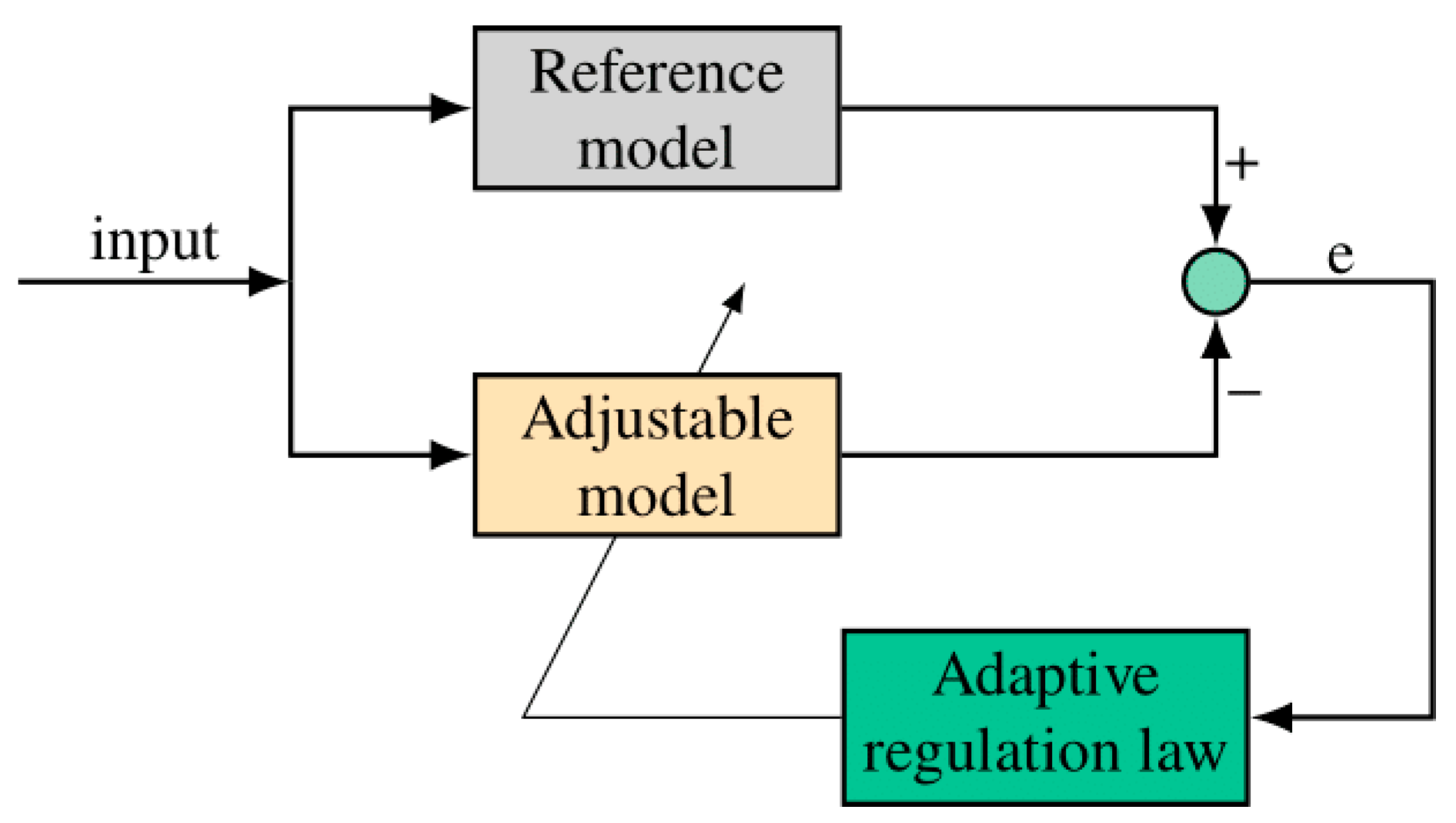
To lessen the impact on the environment that an application has when using PMSMs suggests digitally determining these values in real-time. Two novel approaches are proposed for estimating parameters. In addition, numerous researchers have combined sensorless control with the detection of motor parameters. Although effective, the control rule resulting from using an adaptive fuzzy neural network as a model reference to detect back-EMF (Back Electromotive Force) in the presence of motor parameter perturbations was overly complicated [11]. On the other hand, a two-stage high-gain observer was developed to lessen the impact of parameter perturbation on system identification. Combining the model reference adaptive system (MRAS) with the second-order sliding mode super-twisting algorithm (STA) is a method proposed in (MRAS). The online determination of the resistance value mitigated the effects of uncertainty in the resistance value on the system, allowing for a wider speed range to be achieved with sensorless control. A neural network to calculate the resistance value from the rotor position shift can be utilized [12]. A parallel estimating technique using a super-twisting algorithm and second-order Sequential Minimum Optimization (SMO) algorithm is described, which has shown promising performance at low rates despite the influence of resistance value uncertainty.
This study aimed to introduce a cascade feedback observer identification approach for sensorless control of a brushless DC motor-driven joint drive unit for a lower extremity exoskeleton. This approach is one-of-a-kind because it combines the improved SMO with an adaptive FIR filter. To begin, we create a new SMO that eliminates the talking problem of the first-order SMO without a low-pass filter by building on the upgraded ISF sliding mode control. Lyapunov’s function is used here by SMO to establish a necessary condition for ISF stability.
2.4. MPCC Control Model
Due to its quick response time and easy computation, model predictive current control (MPCC) is a high-performance control method for PMSM drives. Long-term variations in torque and current may be generated by MPCCs. To improve PMSM drives, the authors of this paper propose an alternative MPCC method [13]. The proposed approach uses stator voltage and current data to calculate the back electromotive force and make a current forecast for the subsequent period. The suggested MPCC enhances performance in both static and dynamic conditions by choosing the ideal voltage vector based on the profile of the current track circle rather than a cost function. When compared to the time required to calculate the cost function, the time spent estimating the next track circle is extremely high.
2.5. Fuzzy Controller
The vector controller with PID loops is the most popular control technique for PMSM systems that use fuzzy control [14]. The PMSM model is sensitive to changes in the control performance, making it difficult to choose the appropriate control parameters (KP, ki, and kd) for the PID controller. It is difficult to forecast how a PMSM would perform in the real world due to characteristics such as its operational state, temperature, age, mechanical clearance, and asymmetry.
To enhance the control performance of the PMSM, many complicated control schemes have been created. A few examples are the sliding mode of model predictive control, fuzzy mode, the backstepping technique, mode control, and adaptive control. Several aspects of control performance have been enhanced as a direct result of using these layered controllers. The controller inputs are sensitive to even little variations in PMSM speed or angular velocity, yet are robust against changes in input parameters and external disturbances. In contrast to the mechanical parameters of rotor position and speed, measurements of stator currents and voltages are relatively straightforward. The addition of a rotor position/speed measurement device not only raises the overall system price but also prohibits the system from being downsized and optimized. In light of this, it looks promising to use a control method that does not rely on speed sensors.
2.6. Adaptive N-N Finite-Time Tracking
Finite-time control technique offers superior robustness and anti-disturbance performance compared to asymptotic control. Nonlinear systems have seen a proliferation of finite-time control approaches during the past few decades [7]. For example, they develop a theory of finite-time stability for systems where the state variables take on fractional powers. A new method of adaptive control for PMSM was proposed, and it makes use of ideas from finite-time control theory. Recently, a fast finite-time practical stability criterion for nonlinear systems was devised using backstepping technology with fractional powers. Though the proposed design techniques can yield finite-time tracking, there are “explosion of complexity” and “singularity” concerns linked to them [15]. To address these issues, the command filter control approach was initially devised. Recent theoretical results of adaptive backstepping design using the command-filtered control technique have resulted in a multitude of significant advances for uncertain nonlinear systems. Recently, the backstepping and command filtering technologies were combined to better understand the PMSM’s fuzzy finite-time tracking control problem.
3. Literature Review Methods and Discussion
3.1. Techniques in PMSM
3.1.1. PMSM and High-Frequency Square-Waves Voltage Injection Approach
Through the utilization of MATLAB simulations, Ref. [16] carried out an experiment in which they looked at how the efficiency’s features changed even as the voltage overmodulation index (MI) value changed. During actual dynamometer experimentation, an ideal MI matrix is generated, and the advantages of higher efficiency as well as current ripple reduction were confirmed. The efficiency showed confirmed to have increased by close to 2% because when maximum MI was used compared to the MI = 1.1547 controls approach and also by near to 0.3% compared here to MI = 1.2732 controls method.
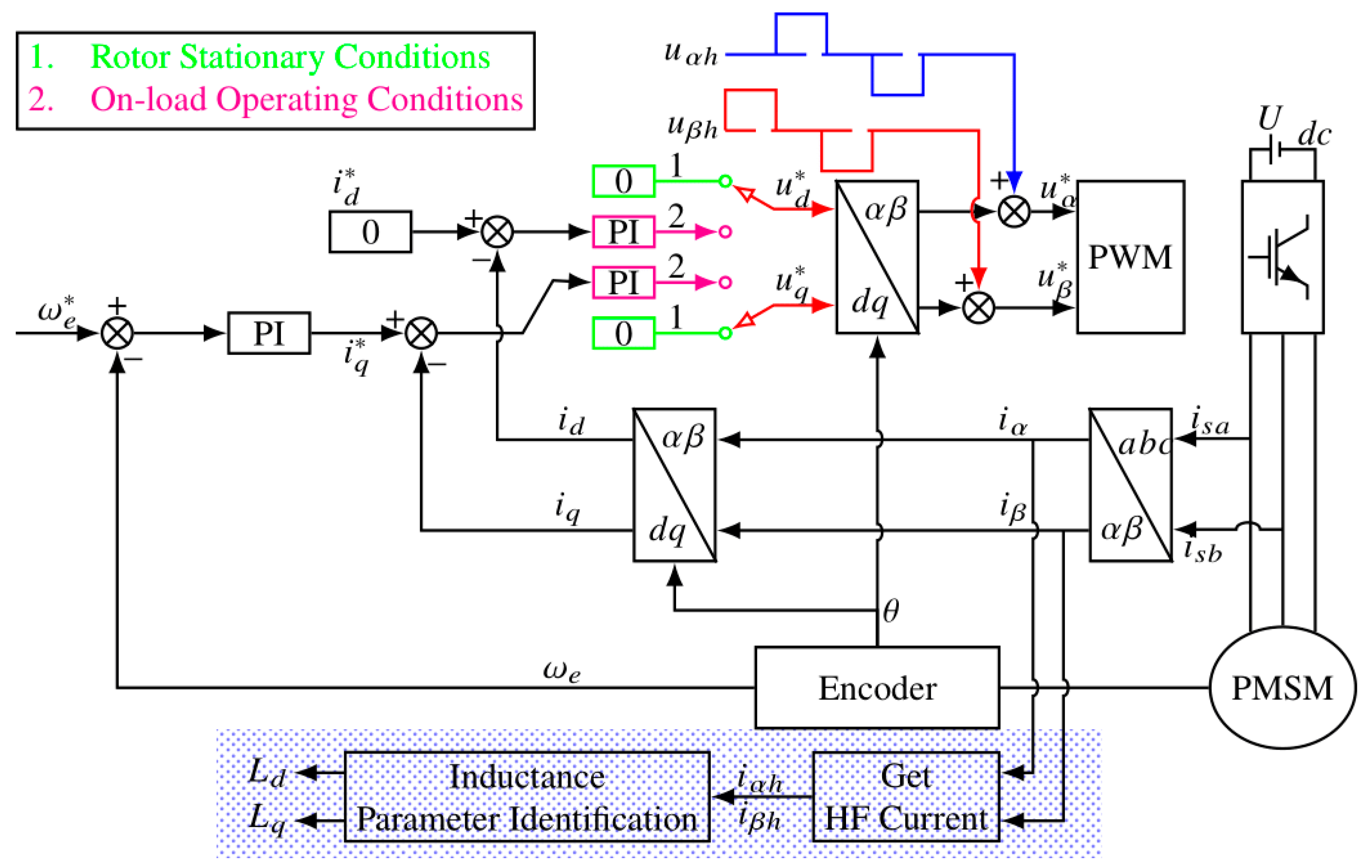
It was also demonstrated that compared to the six-steps control approach, the magnitudes of harmonic ripple currents might be decreased by down to 30%. External factors and influences were not taken into account in this investigation. Depending on the changes in motor parameters, including a changing temperature, their peak efficiency voltage level, for instance, may fluctuate as a consequence of a shift within the current operating spot [16]. High-frequency square-wave voltage injections, see Figure 1, may be used in PMSM drive systems. When the frequency range is too weak, the update frequency of such HF response current will also drop, making it difficult to recover the positional quadrature signals and reducing the efficacy of both control and position estimation.
The HF squares wave voltage injection approach, see Figure 2, is employed in the study [14] to implement sensorless controls in the range between zero and limited bandwidth at a 1 kHz modulation index. Because of the limited injection frequency with low switching frequencies, the projected position ripples are too great since the updated frequency of such position quadrature signals obtained by the square wave’s voltage injection technique is smaller than with the PWM (Pulse Width Modulation) updated frequency.
An approach that relies on CIC (Cascade Integral Comb) interpolations filtering has been suggested throughout this research, according to [14]. That technique minimizes the harmonic components of the positional quadrature signals while improving the frequency response of the signals whenever the implanted square wave’s voltage frequency equals 500 Hz. Either PWM updates the frequency or the anticipated rotational speeds are then used to adjust the delayed angle. According to the simulation results, whenever the speed is modified within a low-speed region of no and over 300 rpm, the program’s position estimations error does not really surpass 0.34 rad, and also, the speed estimation error does not quite surpass 63 rpm. Consequently, the suggested sensorless control approach can enhance the system’s capacity [14].
3.1.2. PMSM Large Power Density and Good Efficiency
As in [17], PMSM is widely employed because of its benefits, including a large power density and good efficiency. Accurately diagnosing the early failures is crucial for ensuring the dependability of either a PMSM system. In order to diagnose the defective positions and severity of such ITSC (inter-turns short-circuit) defects, among the most damaging and common defects in PMSM, a number of optimization approaches are used in this study.
Another publication by the researchers [17] focuses on the ITSC (inter-turns short-circuit) defect of PMSMs and proposes a few fault diagnosis techniques based on heuristics optimization algorithms, such as the particle swarms optimization algorithms, evolutionary algorithms, plus whale optimizations algorithm. The stochastic parallel gradient descent approach is also used because the heuristics algorithm has a significant random component. This approach, known as the stochastics parallel gradient descent algorithm, views the model as just a “black box” and employs random interferences to obtain the estimated gradient. The current defect diagnosis approach algorithm is used to optimize and is evaluated with the genetics algorithm, whale optimization algorithms, and stochastics parallel gradient descents in the simulation accordingly.
The simulation findings in [17] from 2022 showed that the effectiveness of the suggested approaches is strongly encouraging. The stochastics parallel gradient descent approach, in particular, can obtain more consistent diagnostic accuracy with a reduced relative error when compared to other heuristics techniques. Additionally, the approach utilizing stochastics parallel gradient descents still exhibits favorable performance mostly on defect detection for ITSC (inter-turns short-circuit) throughout the presence of asymmetric inputs three-phase voltage and when high-order harmonics during various load instances are taken into account [17].
3.1.3. Operating a PMSM Together in a Fundamental FOC (Field-Oriented Control) Loop
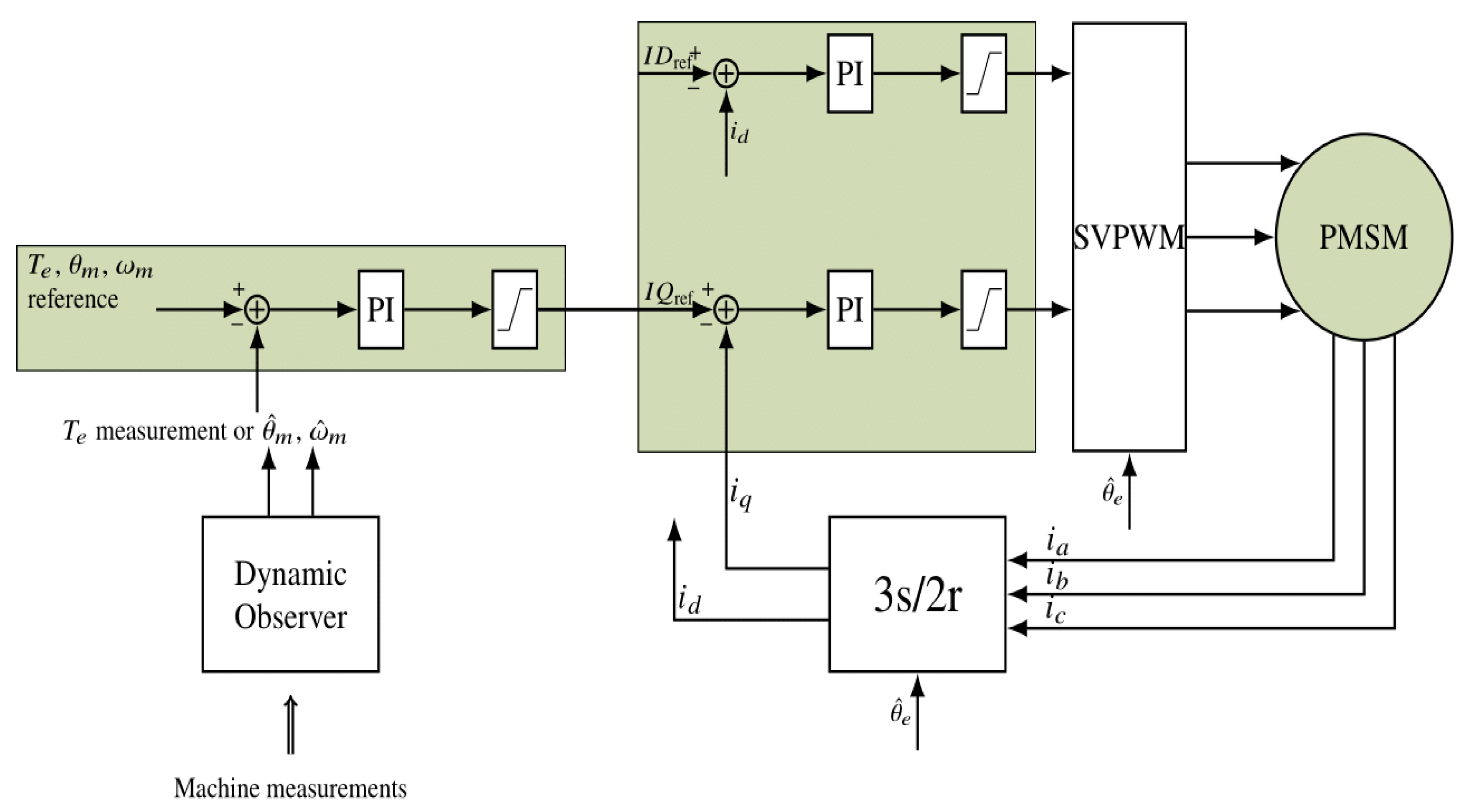
GaN (Generative adversarial network)-based converter’s losses brought generated by the current-collapse phenomenon but also their prevention, respectively, were explored, according to [18]. It became clear that the executive development of on-states resistance, which relies on the modulation scheme being employed and the length of the pulse, is responsible for the extra losses. Following that, the minimum pulses for the GaN (Generative adversarial network) gates drivers are limited in order to regulate the SVPWM (Space vector pulse width modulation) (Pulse Width Modulation) of either a three-phase Voltage Source Inverter (VSI) operating a PMSM together in a fundamental FOC (Field-Oriented Control) loop [18], see Figure 3.
In this study, it was discovered that while the length of the pulse limiting-induced modulated voltage reduces the current-collapses losses, it also introduces current distortion, which increases machine damage. Because the duty cycle limit value affects both converters but also motor losses, that is possible to establish the ideal minimum pulse duration that corresponds to the least amount of power consumed once at the particular steady-state operating point. Additionally, it was discovered through experimentation that perhaps the converter inputs power affects the ideal restricting duty cycle value. In order to fix the duty cycle limit with regard to the real VSI inputs power determined from either the motors currents or voltages, another compensation mechanism was added to the motors control algorithms [18].
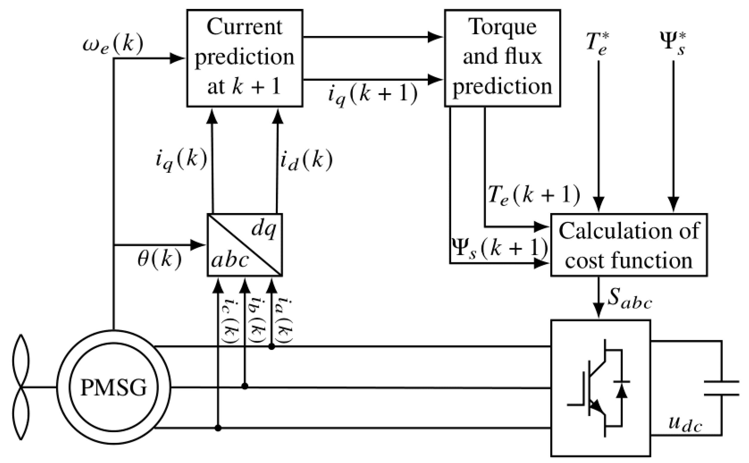
The degradation of the PMSG (permanent magnet synchronous generator) itself during operations must not be disregarded because it lowers the torque and speeds up its reactions and flux ripples to ensure operational stability. To address this issue, a better MPDTC (model predictive direct torque control) approach is suggested, which reduces torque ripples and optimizes PMSG (permanent magnet synchronous generator) efficiency.
3.1.4. Control Technique Based upon MPDTC (Model Predictive Direct Torque Control) for the Optimization Problem of PMSG (Permanent Magnet Synchronous Generator)
The study in [19] suggested an efficient optimal control technique based upon MPDTC (model predictive direct torque control) to address the efficiency optimization problem of PMSG (permanent magnet synchronous generator). This decrease in torque rippling is used to establish minimum wage controls for PMSG (permanent magnet synchronous generator) loss. The enhanced effectiveness by anticipating the operating current of such a stator, MPDTC (model predictive direct torque control), see Figure 4, is able to determine the electromagnetic torques of the generator, enhancing the precision of torque predictions, decreasing torque ripples, and extending the useful life of either the winds turbine [19]. The optimal switch vector could be chosen to use the efficiency optimizations cost function without the weighting coefficient, which can be used to achieve real-time systems efficiency optimization and enhance system reaction time. The efficiency of the suggested control strategy has been confirmed by simulations and experiments, and this strategy is straightforward and simple to use in real-world engineering applications [19].
3.1.5. CT-SMC (Cathode Tube- Safety Monitoring Committee) and F-ST-SMO (Fuzzy Super-Twisted Sliding Mode Observer) Controls System
The authors in [20] investigated the suggested CT-SMC (Cathode Tube-Safety Monitoring Committee) as well as F-ST-SMO (Fuzzy Super-Twisted Sliding Mode Observer) control systems that are based on the PMLSM (Permanent Magnet Linear Synchronous Motor) mathematical model in their work. The PMLSM (Permanent Magnet Linear Synchronous Motor) sensorless systems can operate with high precision using this technique. After analyzing the PMLSMs’ fundamental motion equations, another continuous terminating sliding modes control algorithm is used to develop a speeding closed-loop controller. The statics coordinate system was used to rewrite the voltage equations of the PMLSM, and even the F-ST-SMO (Fuzzy Super-Twisted Sliding Mode Observer), see Figure 5, was created to replace the function of the conventional mechanical sensors. Overall dynamic response of the proposed control system is superior, and indeed the position tracking error is significantly decreased, according to modeling and experimental validation of the controls system under circumstances of fluctuating speeds and loads [20].
3.1.6. Surface-Mounted PMSM
The authors in [21] used a surface-mounted PMSM with random windings that were previously created for such a Formula SAE automobile as either a benchmark case study (2021). In order to replace the randomized winding using hairpin conductors, the very first exercise was performed. Firstly, a preliminary assessment based on the needs of the current application was completed. The analytical formulations are now a secure method for the improvement operation after the comparative sizing tool was validated using Finite Element Method (FEM) evaluations with a maximum deviation of 8%. The optimization technique was then run after doing a sensitivity analysis to weigh the supplied optimization parameters. The benchmark motors using random windings and non-optimal hairpin motors were compared to the ideal motor, which produced extremely encouraging results and notable performance advantages. Effectiveness and volume powers density, while power losses, throughout particular, saw improvements of 0.15 percent, 10.5 percent, and 3.4 percent, respectively [21].
3.1.7. Modulating FCS-MPC (Finite-Control-Set Model Predictive Control) Approach
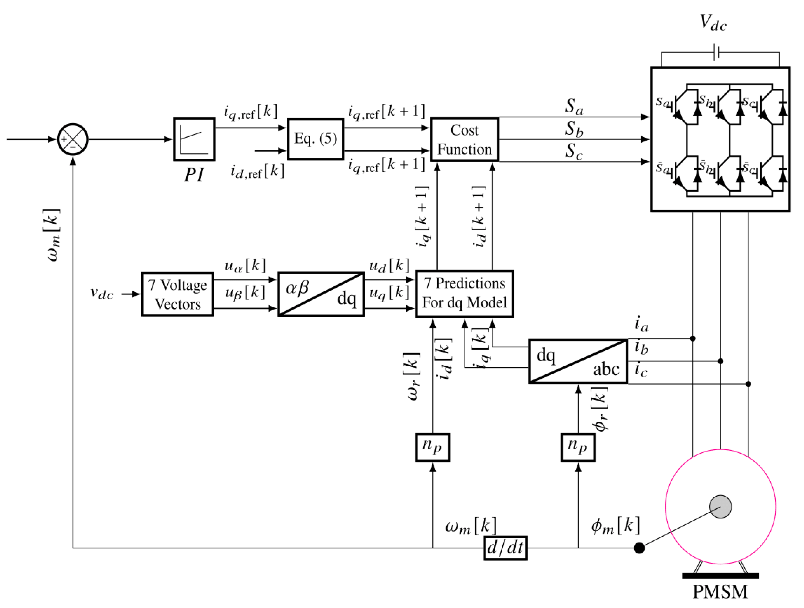
In order to lower the electricity and voltages ripples of both the quasi Z-source inverter (qZSI) and manage the presence of the PMSM across its entire maximum speed without using an excessive degree of loads, Ref. [22] presented a modulating FCS-MPC (Finite-Control-Set Model Predictive Control) approach, see Figure 6. The optimum voltage vectors and the neutral voltage vector are the two times that the postulated M-MPC (Model-based predictive control) separates the sampling intervals. Without having to use the FWC to prevent a highly drawn phase current, the PMSM can operate at speeds higher than its base speed [22]. Even with the suggested M-MPC (Model-based predictive control), overall ripples of such phase current from either buck modes or boost modes were decreased by 42.8 as well as 40.5%; accordingly, in the directions of the D-axis, they were decreased by 50 and 23%, including the q-axis components.
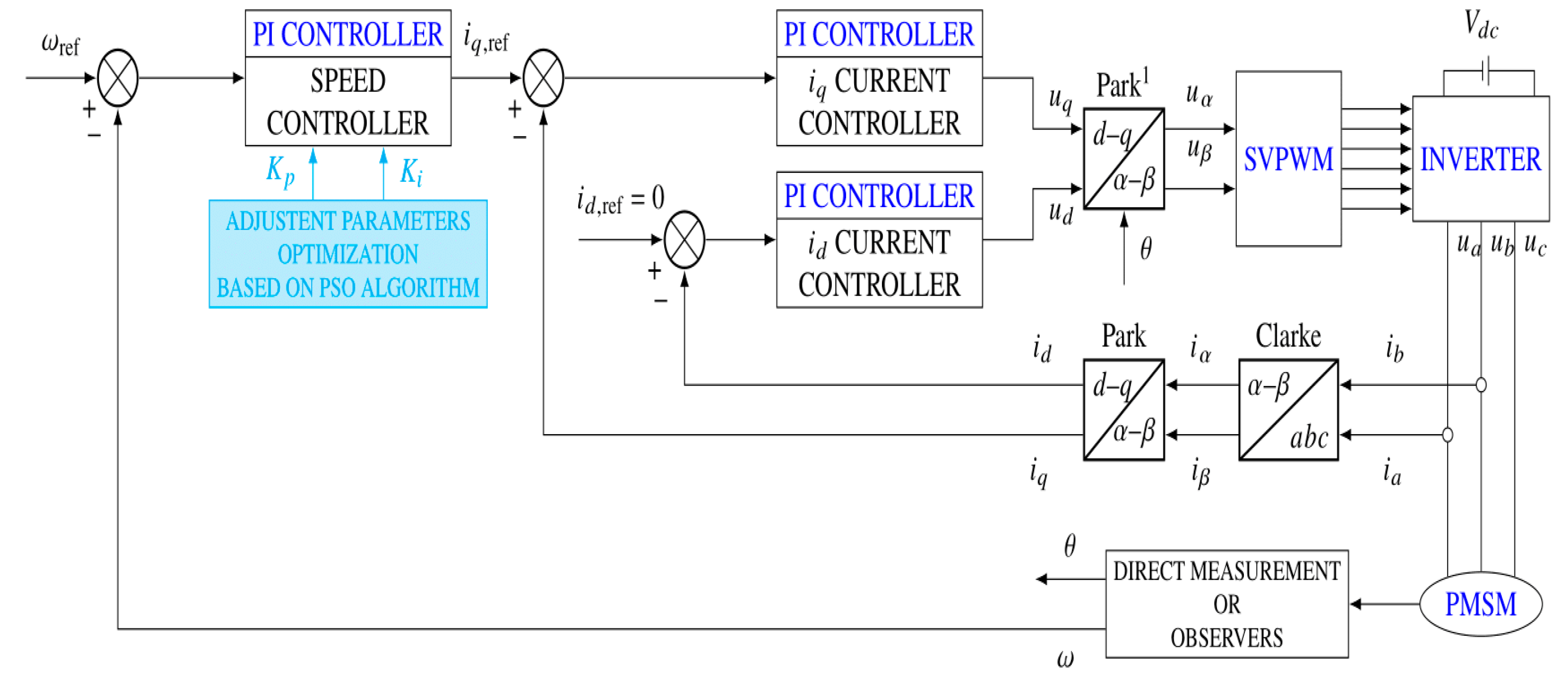
Depending mostly on FOC (Field-Oriented Control)-type classical control structures, in which even the optimizations of the classical PI controller’s tuning parameters are carried out using a PSO (Particle swarm optimization)-type technique, see Figure 7. According to [23], using the PMSMs control method can only guarantee good performances in the situation of minor variations within system parameters rather than in the instance of high dynamics, including abrupt variations in load conditions. Another back stepping-type controls law is created for this purpose, and the nonlinearities of the said control system were embedded therein. The tuning parameters of this process variable are optimized using the PSO (Particle swarm optimization) approach. Another ESO (Extended state observer)-type observation with a response time faster than the control system is designed to estimate the PMSM rotor’s position speeds in order to encompass the system disruptions [23].
3.1.8. Hybrid-Excitation Sustainable HEPM (Hybrid-Excitation Sustainable)
The possibilities and restrictions of HEPM (Hybrid-Excitation Sustainable) synchronous motor are covered in this work, according to [24]. The researcher studied a six-pole device and examined both sequential and parallel arrangements. The permanent magnet (PM) spin flux could be altered in accordance with the rated speed to enhance its system performance by utilizing the rotor stimulation coils. The initial harmonic and whole shape of the electrical force is analyzed [24]. For the current stator regulation, a comparison of numerical versus analytical solutions has also been made.
3.2. Fault Diagnosis of PMSM Motor
3.2.1. Model-Based Method for Transmission Fault Detection and Identifications (FDI (Fault Detection and Identification)) for PMSMs
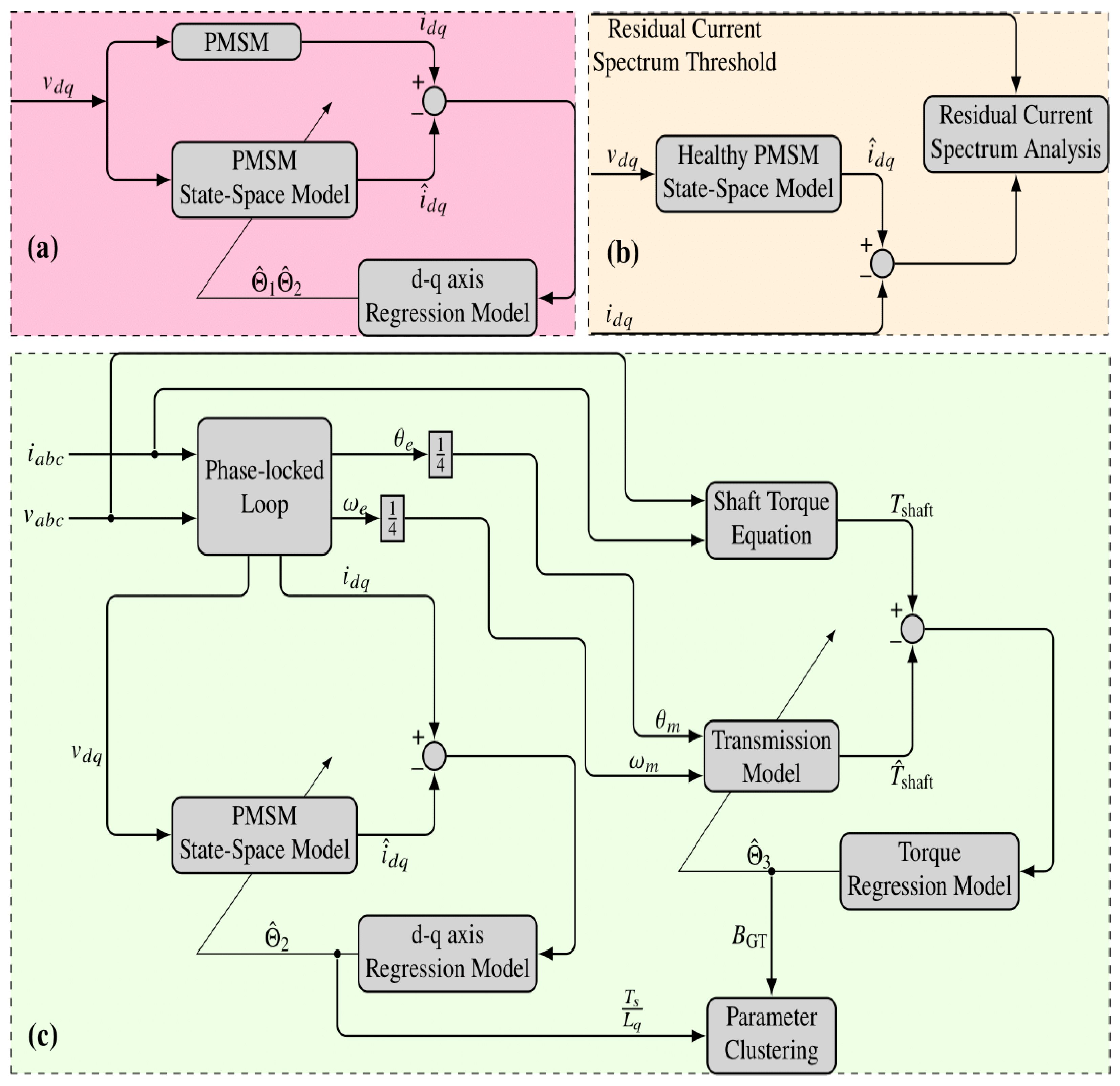
A model-based method for transmission FDI (Fault Detection and Identification) inside a steady-state situation MPSM operation is presented in [25]. This proposed framework builds regression models enabling parameter estimation but uses the Recursive Least-Square (RLS) technique employing a PMSM nation model and then an anticipated transmission model. Both the residual’s current spectrum thresholding approach and parameter clustering are used in the FDI (Fault Detection and Identification) to determine the size of the fault’s characteristic frequency [25], see Figure 8. The trials examine two separate mechanical transmission types under three distinct fault scenarios. This study’s findings demonstrate a promising technique by taking into account both residuals’ current spectra and parameters cluster, which produced good decision making through detecting and diagnosing the defective state as a first step in the monitoring systems of PMSMs drive transmission [25].
3.2.2. Fault Diagnosis Approach for PMSM Based on Vector Spatial
Another fault diagnosis approach that relies on vector spatial decoupling was proposed in [26]. Both current restrictions just after breakdown and indeed the VSD (Ventricular Septal Defects) (Ventricular Septal Defects) inverses transformation are used to determine the open phases fault index. The defect index is optimized to reduce reliability and avoid incorrect diagnoses. One basic cycle may be used to diagnose both single-phase with double faults. Additionally, a neural network gets employed to recognize various fault conditions tracks throughout order to diagnose the switch fault by using the distinct harmonic planes’ current track following VSD (Ventricular Septal Defects) (Ventricular Septal Defects) transformations as the characteristic signals [26]. According to simulations and experiment results, this suggested approach has a quick detection time, the capacity to handle various fault kinds, and an effective immune. The proposed method can also precisely pinpoint the powers switch and wrapping open-circuit faults, which can be utilized to diagnose the inverter’s open-circuit faults and give maintenance workers a foundation.
3.2.3. Fault Diagnosis in Tabulated Comparisons
In this Section a tabulated comparison is reported in which fault diagnosis of different working conditions is compared and briefly analysed. Nevertheless, in Table 1 functional and control conditions together with constructive issues are considered. In Table 2 the analysis of fault detection methods considering different scenarios is taken into account.
3.2.4. Torque Assessment Based on Rotor Irregularity
The change in the vibration and noise for both pole/slot configurations was then examined using torque assessment based on rotor irregularity. The separation of failure signals and fault categorization are the two key components of electric motor diagnosis that are the emphasis in [29] study. The absorption spectra of both positive as well as negative synchronous generators were suggested for a successful solution to the initial problem. Using a straightforward machine learning technique K-Nearest Neighbors (KNN), the cross-short circuits of PMSMs rotor windings were successfully detected and categorized, see Figure 9.
3.3. PMSMs Performances
3.3.1. Potentially Appropriate Asynchronous Motor Replacements
Because of their outstanding efficiency, line-start synchronous motors piqued, as proposed in [30], interest in potentially appropriate asynchronous motor replacements. This interest has really been sparked by stringent rules regulating the applicable efficiency categories of motors here in the EU market. They decided to analyze and optimize the rotor arrangement using inner asymmetric permanent magnets (PM) array rotors in their article.
In order to determine the ideal configuration of the air gap length, magnet thickness, magnet breadth, and number of conductors in every slot, coupled with adjustments to the rotors slot, Ref. [30] conducted an optometric analysis. In comparison to the starting models of the line-starts motor produced again from asynchronous motors, a product of such business Konar, the motor’s outside dimensions remained unaltered. In addition to improved beginning and synchronization capabilities, the optimized model outperformed the starting models in terms of efficiency, power factors, and overloading capacity.
3.3.2. High Dynamic Performance with PMSMs
In order to produce high dynamic performance with a limited number of permanent magnets, Ref. [31] examined the flux intensification (FI) characteristic of permanent magnets aided synchronous reluctance motors (PMa-SynRM) (PM). Therefore, this motor is referred to as the “FI-PMa-SynRM.” In order to illustrate the benefits of the created FI-PMa-SynRM, Ref. [31] examined its performances against that of two comparable counterparts, namely an inset PMSM and even a synchronous reluctances motor (SynRM). Additionally, an investigation of the created FI-PMa-torque SynRM’s density but also partial demagnetizations are carried out to show off its benefits. In order to confirm the efficacy of such FI characteristics, further analysis of flux linkages and inductances is conducted using the finite elements method (FEM). The results of the investigation demonstrated that a significant proportion of PM (0.72% motors volume) could be used to provide a high starting torque density (24.79 Nm/L and even more). Additionally, this anti-demagnetization capability is met [31].
3.3.3. Innovative Rotor Flux Barriers Reconfigurations for Five-Phase PMASynRM (Permanent Magnet Assisted Synchronous Reluctance Machine) and Performance
The authors in [32] research project’s objective would be to introduce and investigate innovative rotor flux barriers reconfigurations for such a five-phase PMASynRM (permanent magnet assisted synchronous reluctance machine), where a standard PMASynRM (permanent magnet assisted synchronous reluctance machine) is taken into account to observe the advantages of the provided rotor schemes. These models are created using the previously examined rotor’s design criteria. Despite the fact that the technical building is created using the same design parameter values, the fluxes barriers technique has indeed been modified, leading to various performances. The proposed models are used in steady-state operation at nominal current and speed with an LPM (Vocal position measurement) carried toward a 2D FEM (2D finite element method) Depending on Comparing the results obtained, both Model-II, Model-V, as well as Model-III sequentially exhibit the highest torque, lowest TCog, and highest ripple when compared to the PMASynRM (permanent magnet assisted synchronous reluctance machine). Complex physical MMF (The magnetomotive force) harmonics contents with higher local saturations within Model-I enhanced the torque ripples [32]. Ultimately, the Model-V is chosen as the ideal rotor design for a five-phase PMASynRM (permanent magnet-assisted synchronous reluctance machine) because it offers high levels of torque density and significantly less torque ripple. In Table 3 a summary of the characteristics and performances is reported.
3.4. PMSMs Characteristics
3.4.1. Characteristics Analysis of PMSMs
In the study [33], the analytical methods were used to do the characteristics analysis of such a permanent magnet synchronous generator, and the effectiveness of the said analytical method has been compared to the accuracy of the finite element method (FEM). Again for the initial concept, the stator’s size was chosen based on the concentration of the stator’s iron core, and indeed the size of the rotor was chosen that used the torques per rotor’s volume technique. The optimum magnets thickness point had also been determined using a rapid Fourier’s transform analysis, where it was proven that perhaps the open circuits and armature reactions magnetics flux densities agreed with the findings of the FEM analysis [32]. The generator circuit constants (phase resistances, back-EMF, but also inductance) were determined using the analytical technique in order to build equivalent circuits. The correctness of either the equivalent circuits approach was verified by contrasting the FEM with experimental results after implementing it against the calculated circuit constants.
3.4.2. Electrical Characteristics of PMSMs
In the investigation of a model that references adaptive systems and simulated annealing particle swarm optimizations (MRAS-SAPSO (Particle swarm optimization)), high-sensitivity identifications of PMSM would be suggested [34], see Figure 10. By using the model references adaptive system approach, the programs first determine the electrical characteristics of such PMSMs (stators winding resistances R, cross-axis inductances L, and magnetics linkage f). Secondly, to further optimize and recognize the mechanical and electrical parameters (moments of inertia J but also damping coefficients B) within the motor controls system, the outcome is employed as the beginning populations in particle swarm optimization identification. The outcomes of said adaptive simulated annealing approach to optimize multiparameter identification also are shown in order to prevent issues such as early convergences of the particle swarm in the optimization selection phase [34].
3.4.3. Comparison of Unidirectional and Bidirectional-Coupled Models
In the study [35], this motor was evaluated just after unidirectional- but also bidirectional-coupled models were developed to replicate the temperature distribution of the motors. The comparison among both testing results or rather analysis findings revealed that perhaps the bidirectional-coupled approach, which takes into account the communication between electromagnetic fields and temperature fields inside the working motors and is more accurate at simulating the motor’s actual functioning process, is more appropriate given that now the motors are an electro magnetism coupled machine [35]. The bidirectional model’s output was more in line with the outcomes of the tests. This bidirectional model can be used to forecast the motor’s temperatures and serve as a guide for the creation of a test-cost-saving design.
3.4.4. Magnetic Field Density of Back-EMF
In a different study, Ref. [36] used an analytical technique to examine the magnetism based on radial eccentric and evaluate the torque density of two paddle combinations. The magnetic field density of back-EMF inside the aperture region was calculated based on the Laplace transform, and electromagnetism theory, as well as the analysis outcome, was confirmed by contrasting with the FEM as well as the observational results. The FEM was used to assess both simulation models with spaces, models, and slots. The authors in [36] confirmed that a slotting model could produce comparable results even when the density of magnetic flux was anticipated as slotless, and thus, a back-EMF is calculated using it.
3.4.5. Nonsingular Terminating Sliding Control Technique of a PMSM
The outcomes of the exploratory studies that have been provided attest to the efficacy of this type of solution, even when the driving system operates online and under various motor operational conditions. To address the issues of high overshooting speed, high torque pulsing at medium speed, and delayed dynamic response brought on by abrupt changes in velocity and load, the authors in [37] presented a nonsingular terminating sliding control technique of a PMSM built on an enhanced exponential approaching law. First, an enhanced exponential approaching law was implemented to the nonlinear function and the outcome curve, while the converging of a random variable and the trajectories of the sliding stage were quantitatively analyzed to determine the accuracy of the approaching law. In order to achieve speed following whenever startup and speed loading varied, an enhanced exponentially extending law-based PMSM velocity loop controlling the sliding mode approach was presented. Eventually, using an enhanced incredibly rapid reaching regulation, a sliding mode observer (SMO) has been created, taking into account the impacts of unpredictability factors such as frequency and interruptions under various working conditions [37], see Figure 11.
3.4.6. Downbeat Predictive Control (DB-PC) Method
A downbeat predictive control (DB-PC) method for perpetual synchronous machines (PMSG (permanent magnet synchronous generator) s) in changeable turbines is suggested in the work [38]. An extended Kalman filter (EKF) was created to estimate the overall disturbance brought on by fluctuations in the PMSG (permanent magnet synchronous generator) parameters in order to increase the resilience of the proposed DB-PC method. The DB-PC technique was then designed with this overall disturbance.
3.5. Future Trends, Challenges, and Opportunities
A study was conducted, and the outcomes demonstrated the improved detection and monitoring techniques suggested in this study [38]. In this study, the standard sliding mode adjustment controls were enhanced by merging the frequency-variable tracker of the stator current (FVTSC) as well as ESO (Extended state observer) to create a statistical method of a six-phase Permanent magnet synchronous motor in the dynamic coordinate system. The old SMO program’s chattering, weak Back-EMF estimate accuracy, and period lag issues were fixed, and its capacity to withstand load disturbances was enhanced in the experimental simulation.
In studies, the maximum static fault and time duration are both reduced relative to the standard nonlinear model predictive speed control (NMPSC) by around 10.294 percent and 23.077 percent, accordingly, as well as the stator position time-weighted absolute value of errors (ITAEs) of the NMPSC with the suggested technique. Additionally, by adjusting the predictive horizon, the median computation burden is reduced by around 0.9 percent, and the servo rigidity and inertia weight sensitivity is enhanced, respectively, by around 18.885 percent and 42.102%. When compared to the traditional method, the AAVE forecast boundary self-tuning technique performs better.
The concept and modeling of a reliable sensorless controller for straight, slender PMSMs were presented in [39]. To make it easier to understand this conceptual underpinning underlying the device’s operation is based, the layout and modeling were completed in a sequential fashion. The speed and combination of a variety made up the two primary circuits of the planned controller. After deriving the controllers’ formulae, the regulators were tuned using those functions [39]. A quick and efficient estimator was created to watch the speed and rotor reluctance in order to improve the system’s dependability. The controller’s efficiency was evaluated under a variety of operating conditions and uncertainties. The acquired results validated the established estimator’s durability and the designed operator’s validity. The direction and speed estimate inaccuracy of the PMSM sensorless motor brought on by stator current was examined in [40]. We suggested an -axis inductor estimation method using probabilistic neural networks (PNNs) deep learning to counteract magnetic saturation.
The trained model was set up to work with a chaotic sensorless controller and was built on the PNN-based group method of data handling (GMDH) algorithm. Additionally, we computed the prediction errors and tracked them in genuine to better prepare for fault scenarios such as an unknown disruption or elevated position distortion inside the sensorless technique [40]. We contrasted and examined the control capabilities for each application of the compensator based on the suggested PNN machine learning algorithm and the theoretical observer model using a simulator and experiment.
In [41] work, the finite set model predictive control (FS-MPC)-based motor drive system has been presented again for FPGA-based actual control implementation utilizing the XSG virtual simulator combined with MATLAB/Simulink (2021). Furthermore, FPGA is used to construct a center frequency sampling rate device for FS-MPC. The motor efficiency during transient operation is significantly influenced by the sampling frequency. With a center frequency data rate, the controller performs better when the standard speed and loading conditions are altered. The precision of the device and the motor current’s constant inaccuracy were examined. Increasing the sampling rate results in a reduction in the constant error.
The electromechanical sensors utilized inside the bearingless permanent magnet synchronous motor (BPMSM) in [42] have some drawbacks, such as growing the size, expense, and difficulty of the motors, and the detecting outcomes are easily influenced by environmental conditions. A motion and elevation sensorless control solution based on least square support vector machine (LS-SVM) left inversion system is suggested in [42] to address these issues. The reliability and efficacy of the LS-SVM left inversion system experimental method suggested in this study are demonstrated by the realization of the detection of rotational speeds and rotor radial displacement.
The study in [43] suggests an enhanced flux-based observer-based control scheme, including dead-time compensation, to accomplish reliable management of PMSMs, using just one angular position estimation approach over the whole speed range. An enhanced flux observer-specific dead-time correcting mechanism is developed to ensure the dependability of the entire control unit. Experimental findings confirmed the suggested sensorless system’s effectiveness. The enhanced circulation sensorless controller that is being presented, including dead-time corrections, is best suited for usage in aided drive applications within electric cars. It may also be utilized for fault diagnosis or fault-tolerance control of such drive systems in electric cars.
The induction motors transmission line control of fuel railway vehicles was studied and analyzed in [44]. Therefore, the researchers suggested that such full permanent magnet transmission system (FPMTS) be built as a concerted control approach between diesel engine persistent magnetic traction motor, taking the PMSM also as its generation and traction engine. The design and execution of both the 2DOF controller and the basic current limit torque control techniques looked at helping the FPMTS work even better [44]. Additionally, a fault protection approach and sliding mode protection management were suggested. The modeling and experimental findings confirmed that its control method and FPMTS achieved an acceptable level of performance.
The procedure of a machine demonstrated the importance of the magnetic field system in enhancing the efficiency of petrol engine railway tracks, as well as research into FPMTS paved the path for future applications of electric machines in high-powered diesel trains and elevated diesel crosses.
The authors in [45] proposed an improved finite set predictive torque control (FS-PTC) in their article to allow the use of a bigger PMSM drive that is indirectly supplied by the converter. Due to the inverter system converter’s lack of a DC-link sensitivity element, the Permanent magnet synchronous motor drive’s volume overall size can be decreased. Since it only uses one switching state over the whole sample period, the standard FS-PTC can result in dangerous conduction for the rectifying phase inside this matrix converter indirectly [45]. Consequently, both experimental and simulation outcomes employing the suggested selection approach were compared between both discrete space vector modulation (DSVM)-based PTC methodologies, namely, PTC-SVD-1 (13 VVs) and PTC-SVD-2 (37 VVs). Based on these findings, the PTC-SVD-2 outperformed the PTC-SVD-1 in terms of stable and rapid torque characteristics. Additionally, compared to PTC-SVD-1, the PTC-SVD-2 demonstrated better robust features against parametric fluctuations.
By merely modifying the speed and frequency amplification in PMSM (Permanent Magnet Sychronous Motors) drives, it is possible to reduce the number of aberrations. [46] demonstrated a new technique and implemented the dynamic spread spectrum technology, RSFPWM (random switching frequency Pulse Width Modulation) under centrosymmetry period with a two-state Markov chain (CPTMC). Enhanced electromagnetic ambient noise radio spectrum features can be attained by optimizing the random number distribution. Those outcomes of the theory were verified from both experimentation and simulation. The adoption of the suggested technique just at frequency variation of first, second, and third has been shown to reduce PSD by around 31.4%, 39.8 percent, and 11.8 percent, as well as harmonic material by around 36.0%, 39.7%, and 60.6 percent when compared to the traditional FSFPWM (fixed switching frequency pulse width modulation Pulse Width Modulation) strategy.
4. Conclusions
The PMSM drive is one of the better choices. For instance, the PMSM is now being investigated for high-power applications, such as industrial motors and vehicle propulsion, and is often utilized for motors, power tools, and robotics. It also has commercial and industrial uses. The PMSM is famous for its outstanding dynamic performance, increased power density, high efficiency, and less power ripple. FPMTS has paved the path for future applications of electric machines in high-powered diesel trains and elevated diesel crosses.
Using a straightforward machine learning technique (KNN), the cross-short circuits of PMSM (Permanent Magnet Sychronous Motors) rotor windings were successfully detected and categorized. The ITSC (inter-turns short-circuit) defect of PMSM proposes a few fault diagnosis techniques based on heuristics optimization algorithms, such as the particle swarms optimization algorithms, evolutionary algorithms, plus whale optimizations algorithm. The stochastic parallel gradient descent approach is also used because the heuristics algorithm has a significant random component. This approach, known as the stochastics parallel gradient descent algorithm, views the model as a “black box” and employs random interferences to attain the estimated gradient. The current defect diagnosis approach algorithm is used to optimize and evaluate the genetics algorithm, whale optimization algorithms, and stochastics parallel gradient descents in the simulation.
PMSM is widely employed because of its benefits, including a large power density and good efficiency. Accurately diagnosing the early failures is crucial for ensuring the dependability of either a PMSM system.
In order to diagnose the defective positions and severity of such inter-turns short-circuit (ITSC (inter-turns short-circuit)) defect, among the most damaging and common defects in PMSMs, a number of optimization approaches are used in the above studies.
Funding
This research received no external funding.
Conflicts of Interest
The authors declare no conflict of interest.
References
- Ali, N.; Alam, W.; Pervaiz, M.; Iqbal, J. Nonlinear adaptive backstepping control of permanent magnet synchronous motor. Rev. Roum. Sci. Tech.-Série Électrotechnique Énergétique 2021, 66, 15–20. [Google Scholar]
- Che, Z.; Yu, H.; Mobayen, S.; Ali, M.; Yang, C.; Bartoszewicz, A. An Improved Extended State Observer-Based Composite Nonlinear Control for Permanent Magnet Synchronous Motor Speed Regulation Systems. Energies 2022, 15, 5699. [Google Scholar] [CrossRef]
- Dai, Y.; Ni, S.; Xu, D.; Zhang, L.; Yan, X.G. Disturbance-observer-based prescribed-performance fuzzy sliding mode control for PMSM in electric vehicles. Eng. Appl. Artif. Intell. 2021, 104, 104361. [Google Scholar] [CrossRef]
- Guo, T.; Sun, Z.; Wang, X.; Li, S.; Zhang, K. A simple current-constrained controller for permanent-magnet synchronous motor. IEEE Trans. Ind. Inform. 2018, 15, 1486–1495. [Google Scholar] [CrossRef]
- Kim, S.K.; Ahn, C.K. Active-damping speed tracking technique for permanent magnet synchronous motors with transient performance boosting mechanism. IEEE Trans. Ind. Inform. 2021, 18, 2171–2179. [Google Scholar] [CrossRef]
- Lan, Y.H.; He, J.L.; Li, P.; She, J.H. Optimal preview repetitive control with application to permanent magnet synchronous motor drive system. J. Frankl. Inst. 2020, 357, 10194–10210. [Google Scholar] [CrossRef]
- Li, T.; Sun, X.; Lei, G.; Yang, Z.; Guo, Y.; Zhu, J. Finite-control-set model predictive control of permanent magnet synchronous motor drive systems—An overview. IEEE/CAA J. Autom. Sin. 2022, 9, 2087–2105. [Google Scholar] [CrossRef]
- Ping, Z.; Ma, Q.; Wang, T.; Huang, Y.; Lu, J.G. Speed tracking control of permanent magnet synchronous motor by a novel two-step internal model control approach. Int. J. Control Autom. Syst. 2018, 16, 2754–2762. [Google Scholar] [CrossRef]
- Ping, Z.; Wang, T.; Huang, Y.; Wang, H.; Lu, J.G.; Li, Y. Internal model control of PMSM position servo system: Theory and experimental results. IEEE Trans. Ind. Inform. 2019, 16, 2202–2211. [Google Scholar] [CrossRef]
- Song, Z.; Yang, J.; Mei, X.; Tao, T.; Xu, M. Deep reinforcement learning for permanent magnet synchronous motor speed control systems. Neural Comput. Appl. 2021, 33, 5409–5418. [Google Scholar] [CrossRef]
- Sun, Z.; Zhang, Y.; Li, S.; Zhang, X. A simplified composite current-constrained control for permanent magnet synchronous motor speed-regulation system with time-varying disturbances. Trans. Inst. Meas. Control 2020, 42, 374–385. [Google Scholar] [CrossRef]
- Tan, L.N.; Pham, T.C. Optimal Tracking Control for PMSM with Partially Unknown Dynamics, Saturation Voltages, Torque, and Voltage Disturbances. IEEE Trans. Ind. Electron. 2021, 69, 3481–3491. [Google Scholar]
- Toso, F.; Carlet, P.G.; Favato, A.; Bolognani, S. On-line continuous control set MPC for PMSM drives current loops at a high sampling rate using qpOASES. In Proceedings of the 2019 IEEE Energy Conversion Congress and Exposition (ECCE), Baltimore, MD, USA, 29 September–3 October 2019; pp. 6615–6620. [Google Scholar] [CrossRef]
- Xue, Z.; Li, L.; Wang, X.; Wang, X. A Sensorless Control Strategy for Permanent Magnet Synchronous Motor at Low Switching Frequency. Electronics 2022, 11, 1957. [Google Scholar] [CrossRef]
- Yu, Y.; Wang, S.; Du, Y.; Viswanathan, V.; Su, R.; Ramakrishna, S.; Gajanayake, C.J.; Gupta, A.K. Application of off-policy integral reinforcement learning for H∞, input-constrained control of permanent magnet synchronous machine. In Proceedings of the 2019 IEEE Applied Power Electronics Conference and Exposition (APEC), Anaheim, CA, USA, 17–21 March 2019; pp. 2570–2576. [Google Scholar] [CrossRef]
- Park, J.H.; Lim, H.S.; Lee, G.H.; Lee, H.H. A Study on the Optimal Control of Voltage Utilization for Improving the Efficiency of PMSM (Permanent Magnet Sychronous Motors). Electronics 2022, 11, 2095. [Google Scholar] [CrossRef]
- Chen, X.; Qin, P.; Chen, Y.; Zhao, J.; Li, W.; Mao, Y.; Zhao, T. Inter-Turn Short Circuit Fault Diagnosis of PMSM (Permanent Magnet Sychronous Motors). Electronics 2022, 11, 1576. [Google Scholar] [CrossRef]
- Skarolek, P.; Lipcak, O.; Lettl, J. Current Collapse Conduction Losses Minimization in GaN (Generative adversarial network) Based PMSM (Permanent Magnet Sychronous Motors) Drive. Electronics 2022, 11, 1503. [Google Scholar] [CrossRef]
- Miao, L.; Lin, F.; Jiang, Y.; Li, Q.; Sun, W. Dynamic Operation Loss Minimization for Permanent Magnet Synchronous Generator Based on Improved Model Predictive Direct Torque Control. Electronics 2022, 11, 1406. [Google Scholar] [CrossRef]
- Li, Z.; Wang, J.; Wang, S.; Feng, S.; Zhu, Y.; Sun, H. Design of Sensorless Speed Control System for Permanent Magnet Linear 678 Synchronous Motor Based on Fuzzy Super-Twisted Sliding Mode Observer. Electronics 2022, 11, 1394. [Google Scholar] [CrossRef]
- Soltani, M.; Nuzzo, S.; Barater, D.; Franceschini, G. A Multi-Objective Design Optimization for a Permanent Magnet Synchronous Machine with Hairpin Winding Intended for Transport Applications. Electronics 2021, 10, 3162. [Google Scholar] [CrossRef]
- Ahmed, A.A.; Bakeer, A.; Alhelou, H.H.; Siano, P.; Mossa, M.A. A New Modulated Finite Control Set-Model Predictive Control of Quasi-Z-Source Inverter for PMSM (Permanent Magnet Sychronous Motors) Drives. Electronics 2021, 10, 2814. [Google Scholar] [CrossRef]
- Nicola, C.-I.; Nicola, M.; Selișteanu, D. Sensorless Control of PMSM (Permanent Magnet Sychronous Motors) Based on Backstepping-PSO (Particle swarm optimization)-Type Controller and ESO (Extended state observer)-Type Observer Using Real-Time Hardware. Electronics 2021, 10, 2080. [Google Scholar] [CrossRef]
- Cinti, L.; Carlucci, M.; Bianchi, N.; Bertoluzzo, M. Electromagnetic and Structural Analysis of Six-Pole Hybrid-Excited Permanent Magnet Motors. Electronics 2021, 10, 2051. [Google Scholar] [CrossRef]
- Purbowaskito, W.; Wu, P.-Y.; Lan, C.-Y. Permanent Magnet Synchronous Motor Driving Mechanical Transmission Fault Detection and Identification: A Model-Based Diagnosis Approach. Electronics 2022, 11, 1356. [Google Scholar] [CrossRef]
- Gao, H.; Guo, J.; Hou, Z.; Zhang, B.; Dong, Y. Fault Diagnosis Method of Six-Phase Permanent Magnet Synchronous Motor Based on Vector Space Decoupling. Electronics 2022, 11, 1229. [Google Scholar] [CrossRef]
- Zou, M.; Yu, J.; Ma, Y.; Zhao, L.; Lin, C. Command filtering-based adaptive fuzzy control for permanent magnet synchronous motors with full-state constraints. Inf. Sci. 2020, 518, 1–12. [Google Scholar] [CrossRef]
- Zhu, P.; Chen, Y.; Li, M. Terminal sliding mode control of permanent magnet synchronous motor based on the reaching law. Proc. Inst. Mech. Eng. Part I J. Syst. Control Eng. 2020, 234, 849–859. [Google Scholar] [CrossRef]
- Pietrzak, P.; Wolkiewicz, M. Online Detection and Classification of PMSM (Permanent Magnet Sychronous Motors) Stator Winding Faults Based on Stator Current Symmetrical Components Analysis and the KNN Algorithm. Electronics 2021, 10, 1786. [Google Scholar] [CrossRef]
- Sarac, V.; Minovski, D.; Janiga, P. Parametric Analysis for Performance Optimization of Line-Start Synchronous Motor with Interior Asymmetric Permanent Magnet Array Rotor Topology. Electronics 2022, 11, 531. [Google Scholar] [CrossRef]
- Hsieh, M.-F.; Ngo, D.-K.; Thao, N.G.M. Flux Intensifying Feature of Permanent Magnet Assisted Synchronous Reluctance Motor with High Torque Density. Electronics 2022, 11, 397. [Google Scholar] [CrossRef]
- Ghorbani, H.; Moradian, M.; Benbouzid, M. On the Optimal Selection of Flux Barrier Reconfiguration for a Five-Phase Permanent Magnet Assisted Synchronous Reluctance Machine for Low-Torque Ripple Application. Electronics 2021, 11, 41. [Google Scholar] [CrossRef]
- Lee, J.-H.; Lee, H.-K.; Lee, Y.-G.; Lee, J.-I.; Jo, S.-T.; Kim, K.-H.; Park, J.-Y.; Choi, J.-Y. Design and Analysis Considering Magnet Usage of Permanent Magnet Synchronous Generator Using Analytical Method. Electronics 2022, 11, 205. [Google Scholar] [CrossRef]
- Su, G.; Wang, P.; Guo, Y.; Cheng, G.; Wang, S.; Zhao, D. Multiparameter Identification of Permanent Magnet Synchronous Motor Based on Model Reference Adaptive System—Simulated Annealing Particle Swarm Optimization Algorithm. Electronics 2022, 11, 159. [Google Scholar] [CrossRef]
- Jia, M.; Hu, J.; Xiao, F.; Yang, Y.; Deng, C. Modeling and Analysis of Electromagnetic Field and Temperature Field of Permanent-Magnet Synchronous Motor for Automobiles. Electronics 2021, 10, 2173. [Google Scholar] [CrossRef]
- Lee, H.-K.; Bang, T.-K.; Lee, J.-I.; Woo, J.-H.; Shin, H.-S.; Yoon, I.-J.; Choi, J.-Y. Analytical Study and Comparison of 672 Electromagnetic Characteristics of 8-Pole 9-Slot and 8-Pole 12-Slot Permanent Magnet Synchronous Machines Considering Rotor 673 Eccentricity. Electronics 2021, 10, 2036. [Google Scholar] [CrossRef]
- Jiang, C.; Wang, Q.; Li, Z.; Zhang, N.; Ding, H. Nonsingular Terminal Sliding Mode Control of PMSM (Permanent Magnet Sychronous Motors) Based on Improved Exponential Reaching Law. Electronics 2021, 10, 1776. [Google Scholar] [CrossRef]
- Abdelrahem, M.; Hackl, C.; Kennel, R. Robust Predictive Control Scheme for Permanent-Magnet Synchronous Generators Based Modern Wind Turbines. Electronics 2021, 10, 1596. [Google Scholar] [CrossRef]
- Mossa, M.A.; Echeikh, H.; Ali, Z.M.; Ahmed, M.; Al-Gahtani, S.F.; Sultan, H.M. Design and Modeling of a Robust Sensorless Control System for a Linear Permanent Magnet Synchronous Motor. Electronics 2021, 10, 966. [Google Scholar] [CrossRef]
- Park, G.; Kim, G.; Gu, B.-G. Sensorless PMSM (Permanent Magnet Sychronous Motors) Drive Inductance Estimation Based on a Data-Driven Approach. Electronics 2021, 10, 791. [Google Scholar] [CrossRef]
- Mishra, I.; Tripathi, R.N.; Singh, V.K.; Hanamoto, T. Step-by-Step Development and Implementation of FS-MPC for a FPGA-Based PMSM (Permanent Magnet Sychronous Motors) Drive System. Electronics 2021, 10, 395. [Google Scholar] [CrossRef]
- Hua, Y.; Zhu, H. Sensorless Control of Bearingless Permanent Magnet Synchronous Motor Based on LS-SVM Inverse System. Electronics 2021, 10, 265. [Google Scholar] [CrossRef]
- Lin, C.; Xing, J.; Zhuang, X. Dead-Time Correction Applied for Extended Flux-Based Sensorless Control of Assisted PMSM (Permanent Magnet Sychronous Motors)s in Electric Vehicles. Electronics 2021, 10, 220. [Google Scholar] [CrossRef]
- Kang, L.; Jiang, D.; Xia, C.; Xu, Y.; Sun, K. Research and Analysis of Permanent Magnet Transmission System Controls on Diesel Railway Vehicles. Electronics 2021, 10, 173. [Google Scholar] [CrossRef]
- Alsofyani, I.M.; Bak, Y.; Lee, K.-B. Improved Finite Set-Predictive Torque Control of PMSM (Permanent Magnet Sychronous Motors) Fed by Indirect Matrix Converter with Discrete Space Vector Modulation. Electronics 2020, 9, 2133. [Google Scholar] [CrossRef]
- Wu, S.; Guo, X.; Wang, R.; Liu, Y.; Lin, L.; Lei, Y. Reduction of Electromagnetic Interference for Permanent Magnet Synchronous Motor Using Random PWM (Pulse Width Modulation) Switching Method Based on Four-Switch Three-Phase Inverters. Electronics 2020, 9, 1998. [Google Scholar] [CrossRef]
Figure 1.
PMSM and High-Frequency Square-Waves Voltage Injection.

Figure 2.
HF Squares Wave Voltage Injection Approach.

Figure 3.
Operating A PMSM Together in A Fundamental FOC Loop (2023).

Figure 4.
Control Technique Based Upon MPDTC for Optimization Problem of PMSG ((2023).

Figure 5.
CT-SMC and F-ST-SMO Controls System.

Figure 6.
Modulating FCS-MPC Approach Using A PSO (Particle Swarm Optimization)-Type Technique.

Figure 7.
Using A PSO-Type Technique.

Figure 8.
(a–c) Model-Based Method for Transmission Fault Detection and Identifications (FDI) For PMSM.
Figure 8.
(a–c) Model-Based Method for Transmission Fault Detection and Identifications (FDI) For PMSM.

Figure 9.
Torque Assessment.

Figure 10.
Adaptive systems and simulated annealing particle swarm optimizations.

Figure 11.
Nonsingular Terminating Sliding Control Technique of a PMSM.


Table 1.
Functional and control conditions.
| PMSM and High-Frequency Square-Waves Voltage Injection Approach. | We provide a new sensorless control strategy for regulating the rotational speed of an interior permanent machine synchronous motor (IPMSM) down to zero rpm via the injection of a high-frequency square-wave signal. In conventional approaches, inverter voltage error can negatively impact rotor position estimate at zero speed, while at low speed, obvious current sampling noise and sluggish identification during magnetic polarity detection might hamper operation. |
| PMSM Large Power Density and Good Efficiency | Thanks to their great efficiency and power density, permanent magnet synchronous motors (PMSMs) are finding more and more applications in the aerospace industry. Motors with a high electromagnetic load and a lightweight frame have been developed to boost power density. When designing motors, only lightweight constructions are employed for the rotor since the saturation performance of iron-core material prevents the use of large magnetic loads. |
| Operating a PMSM Together in a Fundamental FOC (Field-Oriented Control) Loop | Field-oriented control (FOC).is a common method used for PMSMs’ regulation. Some high-performance uses also necessitate rotor position data, which can be obtained via a resolver, for example. Permanent magnet synchronous motors (PMSMs) have their FOC utilized in the development and clarification of a motive system [27]. A resolver sensor is used to determine the system’s location. Through both virtual and physical testing, we can prove that the speed controller, which is part of the drive system, operates as intended. |
| Model Predictive Direct Torque Control (MPDTC)-Informed Control Method for PMSG Optimization (permanent magnet synchronous generator). | Direct torque control (DTC) of PMSG using a Vienna rectifier, however, has not been extensively addressed. To regulate torque and flux while keeping DC-link voltage steady, a switching vector Look-Up Table (LUT) was developed, which defined a DTC based on a PMSG [28]. The LUT itself is very dependent on an offline optimization technique during its construction, which is why the DTC must rely on it for performance. |
| Surface-Mounted PMSM | The sinusoidal back electromotive force of a three-phase external permanent magnet synchronous motor (PMSM) is realized by the Surface Mount PMSM block. The motor’s torque or speed can be adjusted by adjusting the current through the block, which is controlled by the three-phase input voltages. |
| Using a Modulated FCS-MPC (Finite-Control-Set Model Predictive Control) Strategy | The present timestamp is used by continuous control set model predictive control (CCS-MPC) to compare the expected output from time stamps 1 to Np (the prediction horizon) with the reference value, which is derived from the plant’s dynamic mathematical model. It is possible to determine the optimal input of future Nc (control horizon) at any given time by first constructing the cost function and then solving the minimal problem. As PWM modulation is required in the converter’s intended use, the first set of the control sequence is implemented on the converter. |
Table 2.
Analysis of the fault detection methods.
| Model-Based Method For Transmission Fault Detection And Identifications (FDI (Fault Detection and Identification)) For PMSMs | A PMSM state-space model and an approximation transmission model are used to build regression models for parameter estimation in the proposed framework (RLS) algorithm. The FDI is completed by using a thresholding technique on the residual current spectrum to evaluate the magnitude of the fault characteristic frequency. The trials compare two types of mechanical transmission under three distinct failure scenarios. |
| Fault Diagnosis Approach For PMSM Based On Vector Spatial | The stator inter-turn short-circuit fault is one of the most dangerous forms of faults that can occur in PMSMs and put the integrity of PMSM drive systems at risk. There is a method for diagnosing inter-turn short-circuit faults in PMSMs using a finite-control-set model predictive control (FCS-MPC) strategy based on the length of the space vectors. |
| Torque Assessment Based On Rotor Irregularity | When an induction machine has a dynamic rotor problem, such as broken bars or eccentricity, the electromagnetic field around the rotor and, by extension, the magnetomotive force, changes rapidly. Motor current amplitude and phase are modulated as a result of fluctuations in the electromagnetic field. The angular frequency of the spinning electromagnetic field is not constant, but rather, it oscillates around that frequency. |
Table 3.
Charachteristics and Peformances.
| Potentially Appropriate Asynchronous Motor Replacements | Squirrel cage induction motors and wound rotor induction motors are two subsets of the broader asynchronous (induction) motor class. |
| High Dynamic Performance with PMSMs | It helps to think of synchronous motors as being comparable to brushless DC motors in terms of their design and operator to grasp the basic principles involved. Synchronous motors have a more consistent output torque because their coils are not driven by a regulated series of DC pulses, but by numerous phase currents. |
| Innovative Rotor Flux Barriers Reconfigurations for Five-Phase PMASynRM (permanent magnet-assisted synchronous reluctance machine) | To supply and regulate electrical machines, multiphase drive systems can be implemented, even though a three-phase system is the most common. This is because advances in power electronics devices have rendered the necessity of having a restricted number of phases irrelevant. PMASynRM’s ability to use a five-phase system as the driving system is an attractive feature. |
Disclaimer/Publisher’s Note: The statements, opinions and data contained in all publications are solely those of the individual author(s) and contributor(s) and not of MDPI and/or the editor(s). MDPI and/or the editor(s) disclaim responsibility for any injury to people or property resulting from any ideas, methods, instructions or products referred to in the content. |
© 2023 by the author. Licensee MDPI, Basel, Switzerland. This article is an open access article distributed under the terms and conditions of the Creative Commons Attribution (CC BY) license (https://creativecommons.org/licenses/by/4.0/).
Share and Cite
MDPI and ACS Style
Mercorelli, P. Control of Permanent Magnet Synchronous Motors for Track Applications. Electronics 2023, 12, 3285. https://doi.org/10.3390/electronics12153285
AMA Style
Mercorelli P. Control of Permanent Magnet Synchronous Motors for Track Applications. Electronics. 2023; 12(15):3285. https://doi.org/10.3390/electronics12153285
Chicago/Turabian StyleMercorelli, Paolo. 2023. "Control of Permanent Magnet Synchronous Motors for Track Applications" Electronics 12, no. 15: 3285. https://doi.org/10.3390/electronics12153285
Note that from the first issue of 2016, this journal uses article numbers instead of page numbers. See further details here.