Brief Report

Use of a Partially Saturating Inductor in a Boost Converter with Model Predictive Control

Department of Electrical, Electronic, Telecommunications Engineering and Naval Architecture, University of Genoa, Via Opera Pia 11a, 16145 Genova, Italy
*
Author to whom correspondence should be addressed.
Electronics 2023, 12(14), 3013; https://doi.org/10.3390/electronics12143013
Submission received: 27 June 2023 / Revised: 6 July 2023 / Accepted: 7 July 2023 / Published: 9 July 2023
(This article belongs to the Special Issue Modeling and Control in Power Electronics and Electric Drives)

Abstract

:
Increasing the power density in switched mode power supplies is one of the main goals in power electronics. This aim can be achieved by using smaller inductors operating at partial magnetic saturation. In this work, a partially saturating ferrite core inductor is exploited in a switching DC-DC boost converter, regulated through nonlinear model predictive control. A nonlinear behavioral inductor model, identified through experimental measurements, accounts for both magnetic saturation and losses. The simulation results show that the converter output voltage is correctly regulated and the imposed current constraints are fulfilled, even when partial magnetic saturation occurs. Comparisons with traditional control techniques are also presented.

1. Introduction

The magnetic saturation of inductor cores is responsible for a decrease in the permeability of the material as the magnetic field inside the core increases. From the inductor standpoint, this means that the inductance decreases as the current increases, either smoothly (e.g., in powder iron core inductors) or very sharply (e.g., in ferrite core inductors). Several studies showed that exploiting partially saturated inductors allows for increasing the power density of switched mode power supplies (SMPSs), at the cost of a small increase in the power loss. The pioneering work in [1] illustrates the effects of inductor saturation in SMPSs and shows how they can accommodate saturation with a minimal impact on the power consumption. The impact of inductor saturation is further analyzed in [2,3], and the temperature effect is also considered in [4]. The design, simulation, and control of SMPSs with partially saturating inductors require accurate inductor models to properly predict their working behaviors. Several behavioral ferrite core inductor models are reviewed in [5,6], where the inductance and average losses are considered separately. In [7], a unified model is presented, able to also account for the instantaneous losses.
Model predictive control (MPC) is often applied to SMPSs [8], showing better performances compared to model-free proportional integral (PI) regulators. With MPC, indeed, it is possible to exploit a prediction model to enforce input and state constraints. Current constraints, in particular, are important in SMPSs for safety reasons. Four-switch, three-phase rectifiers in balanced grids are considered in [9], whereas inverters in unbalanced grids are addressed in [10]. MPC for a boost converter is proposed in [11] and nonlinear MPC is applied in [12]. However, few implementations considering a nonlinear inductance are available. Different nonlinearities (including magnetic saturation) are considered in [13], where the inductance of a powder iron core inductor is modeled as an exponential function and a fast gradient optimization algorithm is used, which does not allow imposing current constraints. Concerning ferrite core inductors, in [14], an explicit MPC controller is designed for a buck converter by considering a very simplified inductor model with a step-like inductance and no losses. In this work, we perform the voltage regulation of a DC-DC boost converter by imposing current constraints and by exploiting the ferrite core inductor model proposed in [7], where the inductance is an arctangent function of the current and instantaneous losses are accounted for. This model is much more accurate than the one used in [14]. The simulation results show the good performance of the proposed nonlinear MPC (NMPC) compared to traditional regulators.
The main novelty of this work is the exploitation of an accurate ferrite core inductor model for the regulation of a boost converter through nonlinear model predictive control. We show that, if saturation is taken into account by the controller, a correct regulation is achieved by fulfilling the imposed constraints.

2. Materials and Methods
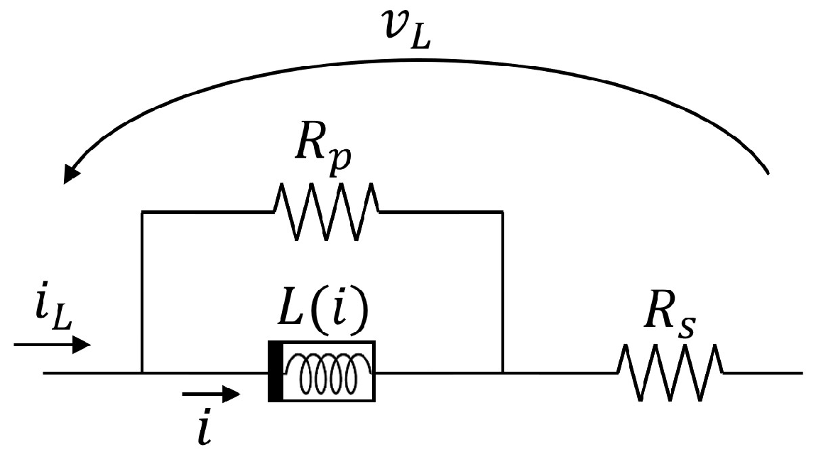
2.1. Inductor Model

The ferrite core inductor is modeled as in [7] by exploiting a nonlinear conservative inductor with flux ϕ and current i and two linear resistors with resistance R s and R p that capture all the instantaneous power losses (see Figure 1).
The differential inductance L = d ϕ d i is expressed as
L ( i ) = L s a t + L n o m L s a t 2 1 2 π t a n 1 σ i I
The parameter vector ξ = R s , R p , L n o m , L s a t , σ , I is identified starting from experimental measurements of the inductor voltage and current [7]. Several sinusoidal voltages v L ( j ) ( t ) with frequency f (period T = 1 f ) and root mean square (RMS) values E ( j ) ( j = 1 , , J ) are applied to the physical inductor. The measurements of the corresponding inductor currents are denoted as i L ( j ) ( t ) . The current i ( j ) ( t ) flowing through the conservative inductor can be computed as i ( j ) = i L ( j ) v L ( j ) R s i L ( j ) R p . Based on these measurements and the proposed model, the measured and estimated inductor fluxes are evaluated, respectively, as
ϕ ^ ( j ) ( t ) = v L ( j ) ( t ) d t + Φ 1 ( j )
ϕ ( j ) ( t ; ξ ) = L ( j ) d i ( j ) + R s i L ( j ) ( t ) d t + Φ 2 ( j )
where L ( j ) is the inductance of Equation (1) computed based on i ( j ) , whereas Φ 1 ( j ) and Φ 2 ( j ) are chosen such that the average value of the fluxes at steady state over a period is null (inductor volt second balance [15]). Clearly, ϕ ( j ) depends on ξ as it is computed based on L ( j ) and its parameters (see Equation (1)), R s , and R p (through i ( j ) ). Therefore, the model parameters can be fitted to the measurements by solving the following nonlinear optimization problem:
min ξ j = 1 J 1 T 0 T ϕ ^ ( j ) ( t ) ϕ ( j ) ( t ; ξ ) 2 d t
As all measurements are obtained with a sampling time of 2 μ s , all the above integrals are computed numerically with the trapezoidal method.

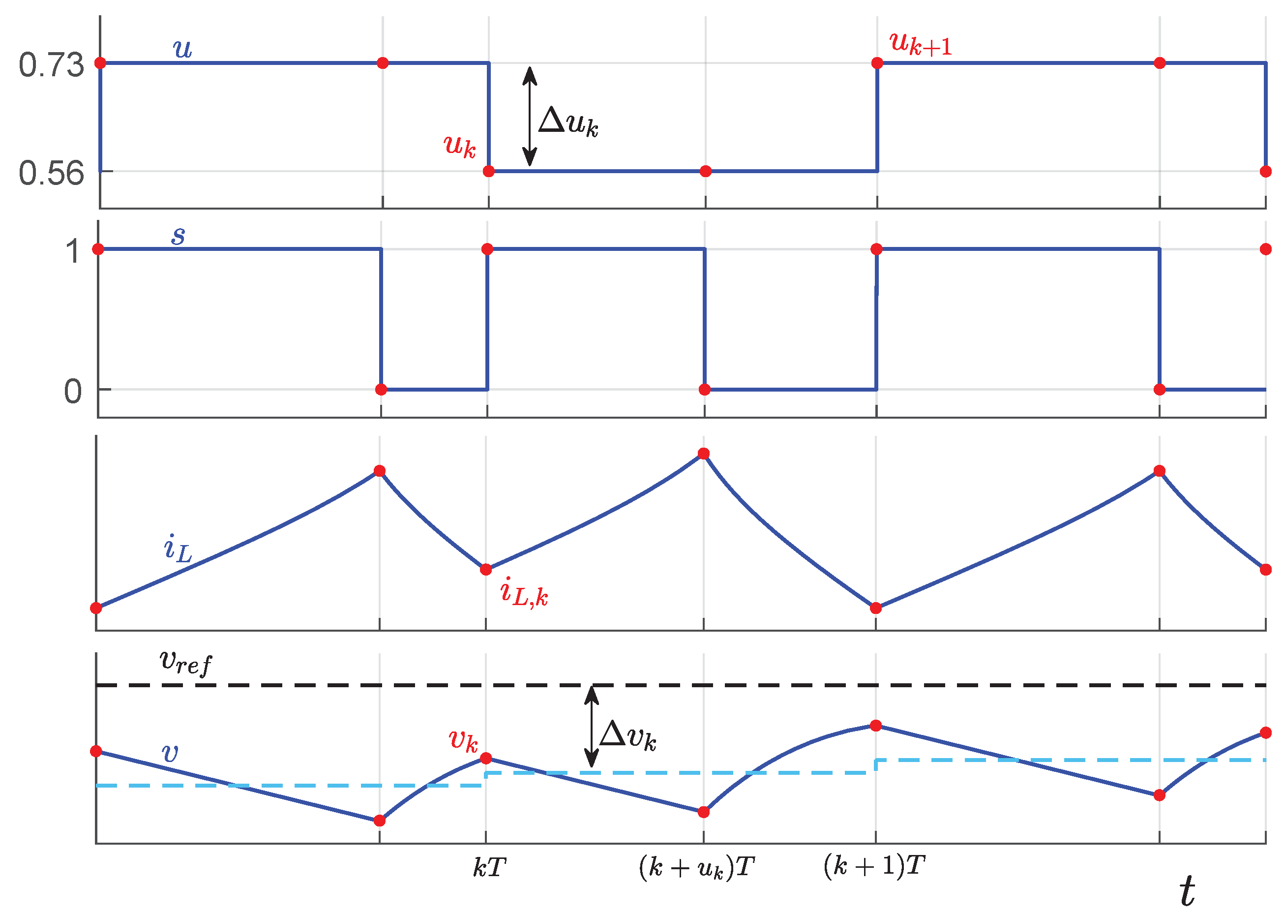
2.2. Boost Converter Model

We consider the nonlinear model predictive control of a DC-DC boost converter, whose circuit model is shown in Figure 2.
The MOS transistor, whose losses are captured by the resistance R M O S , is controlled through a pulse width modulation (PWM) signal s with a fixed frequency f (period T = 1 / f ) and variable duty cycle u. s = 1 if the MOS conducts current (ON phase) and s = 0 otherwise (OFF phase). The system state and input are x = [ i , v ] and u, respectively. The input voltage V i n and output current I o u t are considered as measurable parameters, gathered in a vector p = [ V i n , I o u t ] .
The continuous-time dynamics of the boost converter are defined by the following nonlinear differential system:
d x d t = F ( x , u , p , t ) = R p ( V i n v d R s i v ) L ( i ) R s + R p R p i v + V i n v d ( R s + R p ) I o u t C ( R s + R p ) , if   s ( u , t ) = 0 R p [ V i n ( R s + R M O S ) i ] L ( i ) R s + R p + R M O S I o u t C , if   s ( u , t ) = 1
and the current i L can be evaluated as
i L = G ( x , u , p , t ) = R p i + V i n v d v R s + R p , if   s ( u , t ) = 0 R p i + V i n R s + R p + R M O S , if   s ( u , t ) = 1
The state variable v is directly measurable on the circuit, whereas i is not available in the real circuit. However, it can be computed through Equation (6), starting from the measurable quantities s, v, i L , and V i n :
i = ( R s + R p ) i L V i n + v d + v R p , if   s ( u , t ) = 0 ( R s + R p + R M O S ) i L V i n R p , if   s ( u , t ) = 1
The typical time evolution of the state and input variables during the converter operation are shown in Figure 3. The k-th PWM period, characterized by a duty cycle u k , starts at time k T (when s goes to 1) and ends at time ( k + 1 ) T . Signal s goes to 1 at time k T and to 0 at time ( k + u k ) T . We denote T S as the set of switching instants. Signal u ( t ) is a piecewise constant function, with u ( t ) = u k for k T t < ( k + 1 ) T . Both the inductor current and the output voltage exhibit a ripple. The average value of v within each PWM period is shown as a cyan dashed line in the middle panel of Figure 3; the aim of the controller is to impose that this average value reaches a desired reference v r e f , shown with the black dashed line. The distance between the reference and average output voltages within the k-th PWM period is defined as Δ v k = 1 T k T ( k + 1 ) T v ( t ) d t v r e f . Finally, we indicate with Δ u k = u k u k 1 the difference between two subsequent duty cycle values.
Let v k , i L , k , V i n , k , and I o u t , k be the measurements of the output voltage, inductor current, input voltage, and output current, respectively, at time k T . By exploiting Equation (7), we can compute i k , then x k = [ i k , v k ] and p k = [ V i n , k , I o u t , k ] . The NMPC action u k is obtained by solving the following nonlinear optimization problem:
min U P Δ v k + N 2 + j = 0 N 1 R Δ u k + j 2 + Q Δ v k + j 2
s . t . d x d t = F ( x , u , p k , t ) i L = G ( x , u , p k , t ) t k T , ( k + N ) T
x ( k T ) = x k
u ( t ) = u k + j , for ( k + j ) T t < ( k + j + 1 ) T , j = 0 , , N 1
0 i L ( t ) i m a x , t T S [ k T , ( k + N ) T ]
u m i n u k + j u m a x , j = 0 , , N 1
u k + j = u k + N u 1 , j = N u , , N 1
The optimization variables for this problem are gathered in a vector U = [ u k , , u k + N 1 ] , but only u k is applied to the system, and problem (8) is solved again at time ( k + 1 ) T in a receding horizon fashion. Nonlinear differential system (8b), used for prediction, with initial conditions (8c) and piecewise constant input u ( t ) as in Equation (8d), can be solved with any numerical integration method by assuming that p k remains constant within the whole prediction horizon. Equations (8e) and (8f) represent state and input constraints, respectively. As shown in Figure 3, state variables are monotonic between two subsequent switching times (red dots). Therefore, constraint (8e) can be applied only at switching instants within the prediction horizon. Finally, Equation (8g) sets the value of u k after the control horizon N u .

3. Results

3.1. Inductor Model Identification

We consider a boost converter equipped with a Coilcraft MSS1038T-273 SMD ferrite core inductor with a nominal inductance of 27   μ H [16] and an IXTP230N075T2 MOS. The PWM frequency is f = 50 k Hz (period T = 20   μ s ) . The parameter vector ξ is identified by applying to the inductor a sinusoidal voltage with frequency f = 50 k Hz and RMS value of 18.96 V and by measuring the corresponding inductor current. The nonlinear optimization problem (4) is then solved. A further seven sinusoidal voltage waveforms with RMS values of 3.15, 6.46, 9.76, 12.96, 16.03, 17.61, and 18.48 V are applied to the inductor for validation purposes. In all tests, the relative RMS and maximum errors of the flux are below 2.5% and 6%, respectively, with respect to the maximum flux among all measurements. Since the behavior of the inductor is sensitive to temperature variations [17], measurements were taken after the thermal transient had subsided. The identified model parameters are listed in Table 1, whereas Figure 4 shows the corresponding differential inductance L of the conservative inductor as a function of i. Notice that the inductance decreases as the inductor approaches magnetic saturation. The top panel of Figure 5 shows the measured (black dashed curves) and estimated (colored curves) inductor currents i L corresponding to the RMS voltage values of 6.46 (blue), 12.96 (green), 17.61 (orange), and 18.96 V (red). The estimated currents are evaluated based on the inductor model by solving the following ordinary differential equation [7]:
d i d t = R s R p L ( R s + R p ) i + R p L ( R s + R p ) v L i L = R p R s + R p i + 1 R s + R p v L
The bottom panel shows instead the measured (black dashed curves) and estimated (colored curves) inductor instantaneous absorbed power p L . The estimations are in good agreement with the measurements, even when the waveforms are distorted due to the nonlinear inductance decrease.

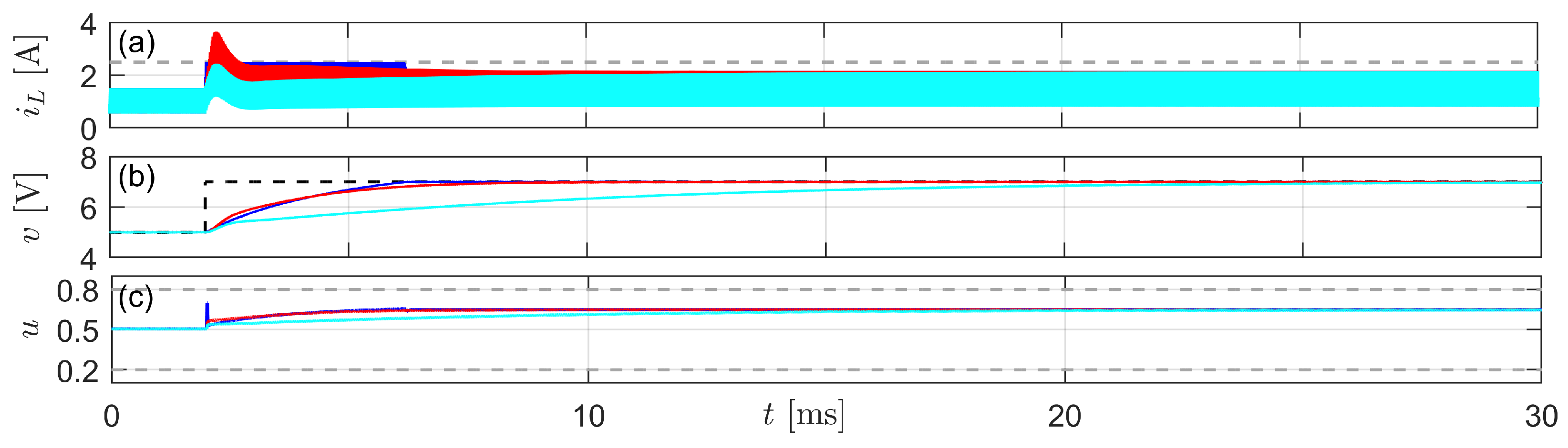
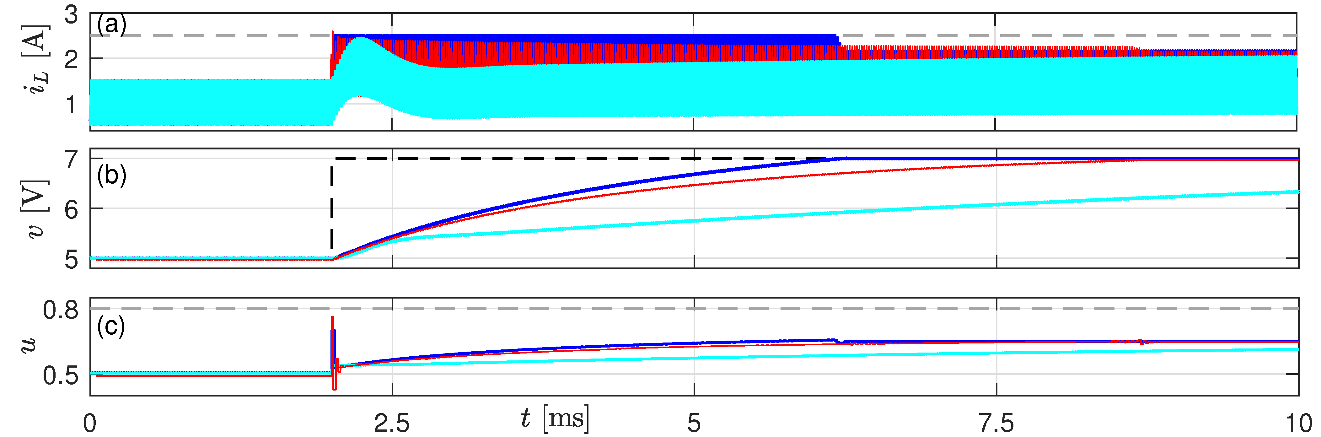
3.2. Simulation Results

The boost converter was simulated in the Simscape environment by using the Specialized Power Systems library that includes models of all power converter components. Problem (8) is solved through the MATLAB function fmincon by integrating the continuous time system (8b) through the function ode45. The circuit and control parameters are listed in Table 2 and Table 3, respectively.
In the considered scenario, V i n is changed from 0 to 3 V in about 5 m s , and the output voltage reference is v r e f = 5 V for 6 m s , then it is increased to 7 V . The simulation results are shown in Figure 6 (blue curves), where the nonlinear inductance (1) is used both in the simulation model and for NMPC prediction. Panel (a) shows the inductor current i L ( t ) with its imposed upper bound i L , m a x (dashed gray line). The output voltage v ( t ) and its reference value v r e f (dashed black line) are shown in panel (b). Panel (c) shows the duty cycle u ( t ) with its bounds (dashed gray lines), and panel (d) shows the instantaneous inductance value. Notice that the inductance decreases up to about one-half of its nominal value; therefore, the inductor operates also in its nonlinear region. This is also confirmed by the insets in the figure, highlighting the cusp-like shape of the current waveform. As the current increases, indeed, the slope of the curve, which is inversely proportional to the inductance, also increases. The results show that the output voltage correctly reaches its reference value and all constraints are met, even if the inductor works in partial saturation. In response to a step in the reference voltage, the output reaches its desired value in about 4 m s .
The green curves in the figure are obtained by assuming a constant inductance L = L n o m in the NMPC prediction model (8b) and a nonlinear inductance in the simulation model. In this case, the model is not aware of the inductor saturation and, even if the output voltage is correctly regulated to its reference value with faster dynamics, current constraints are not fulfilled during transients. This also causes evident oscillations in the duty cycle.
For comparison purposes, a first traditional voltage mode PI controller (called fast PI) is also designed, where
u = K p ( v r e f v ) + K i ( v r e f v ) d t
The simulation results are shown in Figure 7 in response to a change in v r e f from 5 to 7 V . The blue curves are the same as in Figure 6, obtained with the NMPC controller exploiting the nonlinear inductance, whereas the red lines are obtained with the fast PI controller, tuned to have almost the same convergence time as MPC, with K p = 0.028 and K i = 1500 . Notice that this PI controller is not always able to meet the constraints, as the current exceeds 2.5   A during the transient. A slow PI controller (cyan curves), with K p = 0.017 and K i = 620 , is designed to fulfil the current constraints; however, in this case, the convergence time is much higher than for NMPC, as v needs about 14 m s to reach the reference value.
It is well known that controllers with nested loops often offer better performances compared to voltage mode regulators [18]. Then, we also implemented peak current mode control [19], where the SMPS output voltage is compared to the reference voltage, and a PI controller (with proportional and integral gains equal to 20 and 200, respectively) is used to obtain a reference current signal i r e f . The PWM signal goes to 1 at the beginning of each period and it goes to 0 whenever the inductor current reaches i r e f . Due to the inherent instability of the method for duty cycles higher than 0.5, slope compensation is adopted [19]. The results for NMPC, slow PI, and peak current mode control are compared in Figure 8. The current mode control allows imposing constraints on the inductor current (by saturating i r e f ), and as such its performance is much better than the slow PI. However, also in this case, the NMPC controller allows achieving a faster (by about 2.5   m s ) convergence time. Moreover, NMPC requires sampling the inductor current only at the beginning of the PWM period, whereas the acquisition of the whole waveform is necessary for peak current mode control, which requires fast analog-to-digital converters.

4. Discussion

Traditionally, inductor saturation is avoided in power converters, the inductance is assumed to be constant, and power losses and current ripple are easily predictable. In this case, both PI (model-free) regulators and model-based controllers as MPC are successfully applied for the converter control. If the model is sufficiently accurate, MPC usually outperforms PI controllers, being able to inherently enforce state and input constraints.
To increase the power density in SMPSs, we could exploit smaller inductors and a higher switching frequency in order to reduce the current ripple and prevent saturation. This can be done at the cost of an increase in the losses in both the inductor and the semiconductor devices implementing the switch. Moreover, it is not always possible to increase the frequency as desired, due to external limitations. As an alternative, smaller inductors operating in partial saturation may be exploited by keeping the original switching frequency. In this case, MPC requires an accurate inductor model to predict its behavior when approaching saturation. The results of this work show that the behavioral inductor model proposed in [7] can be used within NMPC and allows for correct voltage regulation of a switching converter, also when the inductor operates in partial saturation, by enforcing constraints. If a standard inductor model (with constant inductance) was used, on the contrary, constraints would be violated. With the proposed model, NMPC outperforms standard PI regulators. The next step for this research is to implement the NMPC controller on a digital device (e.g., a field programmable gate array) and apply it to a real converter. This will allow for assessing the robustness of the method against noise and model uncertainties and its ability to meet the imposed sampling time, which is mandatory in order for the controller to be used. Of course, the real-time implementation of the proposed controller is not straightforward, as NMPC requires solving a nonlinear optimization problem at each sampling interval, which can be on the order of microseconds for SMPSs. Several FPGA implementations of NMPC have been proposed in the literature [20,21,22,23,24]; in particular, in [24], a derivative-free optimization algorithm [25] is exploited for the control of a DC-DC boost converter with a linear inductor by achieving a latency of about 15 μ s . The hardware implementation of the controller proposed in this paper and testing it on a real converter prototype will be the subject of future research.
We remark that the benefits of exploiting partially saturating inductors to increase the power density in switching converters can be appreciated also by resorting to standard model-free control techniques (e.g., voltage mode or peak current mode regulators). However, if the converter sampling interval is higher than the computation time, NMPC ensures better SMPS performances.

5. Conclusions

In this work, a recently proposed accurate nonlinear inductor model has been exploited for the voltage regulation of a boost converter through NMPC. The simulation results show that the controller is able to regulate the converter’s output voltage by fulfilling current constraints, even when the inductor operates at partial magnetic saturation. Further work will be concerned with the implementation of NMPC on an FPGA and the validation of the controller on a real prototype, thus assessing its robustness against measurement noise and model inaccuracies.

Author Contributions

Conceptualization, A.O., M.L., A.R. and M.S.; software, P.F.; formal analysis, P.F. and A.R.; data curation, A.R.; writing—original draft preparation, A.R. and A.O.; writing—review and editing, M.S. and M.L.; supervision, M.S. and A.O.; funding acquisition, A.O. All authors have read and agreed to the published version of the manuscript.

Funding

This work was partially funded by the European Union-NextGenerationEU, within the project “MAGSAT-Exploiting MAGnetic SATuration to increase power density in switching converters”, University of Genoa, Italy.

Data Availability Statement

All data generated and analyzed in this study are included in this published article. The source code for the numerical simulations presented in the paper will be made available upon reasonable request to the corresponding author.

Conflicts of Interest

The authors declare no conflict of interest.

References

  1. Milner, L.; Rincón-Mora, G.A. Small saturating inductors for more compact switching power supplies. IEEJ Trans. Electr. Electron. Eng. 2012, 7, 69–73. [Google Scholar] [CrossRef] [Green Version]
  2. Di Capua, G.; Femia, N. A novel method to predict the real operation of ferrite inductors with moderate saturation in switching power supply applications. IEEE Trans. Power Electron. 2016, 31, 2456–2464. [Google Scholar] [CrossRef]
  3. Di Capua, G.; Femia, N.; Stoyka, K. Impact of Inductors Saturation on DC-DC Switching Regulators. In Proceedings of the IEEE International forum on Research and Technology for Society and Industry (RTSI), Florence, Italy, 9–12 September 2019; pp. 254–259. [Google Scholar]
  4. Scirè, D.; Lullo, G.; Vitale, G. Assessment of the Current for a Non-Linear Power Inductor Including Temperature in DC-DC Converters. Electronics 2023, 12, 579. [Google Scholar] [CrossRef]
  5. Oliveri, A.; Lodi, M.; Storace, M. Nonlinear models of power inductors: A survey. Int. J. Circuit Theory Appl. 2022, 1, 2–34. [Google Scholar] [CrossRef]
  6. Scirè, D.; Lullo, G.; Vitale, G. Non-Linear Inductor Models Comparison for Switched-Mode Power Supplies Applications. Electronics 2022, 11, 2472. [Google Scholar] [CrossRef]
  7. Ravera, A.; Oliveri, A.; Lodi, M.; Storace, M. A nonlinear behavioral model of a ferrite-core inductor with fixed-frequency sinusoidal voltage input. In Proceedings of the IEEE International Conference on Smart Techonologies (EUROCON), Turin, Italy, 6–8 July 2023. [Google Scholar]
  8. Karamanakos, P.; Geyer, T.; Oikonomou, N.; Kieferndorf, F.D.; Manias, S. Direct model predictive control: A review of strategies that achieve long prediction intervals for power electronics. IEEE Ind. Electron. Mag. 2014, 8, 32–43. [Google Scholar] [CrossRef]
  9. Liu, Y.C.; Ge, X.; Tang, Q.; Deng, Z.; Gou, B. Model predictive current control for four-switch three-phase rectifiers in balanced grids. Electron. Lett. 2017, 53, 44–46. [Google Scholar] [CrossRef]
  10. Jin, T.; Wei, H.; Legrand, D.; Nzongo, M.; Zhang, Y. Model predictive control strategy for NPC grid-connected inverters in unbalanced grids. Electron. Lett. 2016, 52, 1248–1250. [Google Scholar] [CrossRef]
  11. Bououden, S.; Hazil, O.; Filali, S.; Chadli, M. Modelling and model predictive control of a DC-DC Boost converter. In Proceedings of the 2014 15th International Conference on Sciences and Techniques of Automatic Control and Computer Engineering (STA), Hammamet, Tunisia, 21–23 December 2014; IEEE: Piscataway, NJ, USA, 2014; pp. 643–648. [Google Scholar]
  12. Lekić, A.; Hermans, B.; Jovičić, N.; Patrinos, P. Microsecond nonlinear model predictive control for DC-DC converters. Int. J. Circuit Theory Appl. 2020, 48, 406–419. [Google Scholar] [CrossRef]
  13. Stickan, B.; Frison, G.; Burger, B.; Diehl, M. A nonlinear Real-Time Pulse-Pattern MPC Scheme for Power-Electronics Circuits Operating in the Microseconds Range. In Proceedings of the American Control Conference, Atlanta, GA, USA, 8–10 June 2022; pp. 2070–2077. [Google Scholar]
  14. Mariethoz, S.; Herceg, M.; Kvasnica, M. Model Predictive Control of buck DC-DC converter with nonlinear inductor. In Proceedings of the 11th Workshop on Control and Modeling for Power Electronics, Zurich, Switzerland, 17–20 August 2008; pp. 1–8. [Google Scholar]
  15. Erickson, R.W.; Maksimovic, D. Fundamentals of Power Electronics; Springer Science & Business Media: New York, NY, USA, 2007. [Google Scholar]
  16. Coilcraft. MSS1038T Series. Available online: https://www.coilcraft.com/en-us/products/power/shielded-inductors/ferrite-drum/mss-mos/mss1038t/ (accessed on 6 July 2023).
  17. Lodi, M.; Bizzarri, F.; Linaro, D.; Oliveri, A.; Brambilla, A.; Storace, M. A Nonlinear Behavioral Ferrite-Core Inductance Model Able to Reproduce Thermal Transients in Switch-Mode Power Supplies. IEEE Trans. Circuits Syst. I Regul. Pap. 2020, 67, 1255–1263. [Google Scholar] [CrossRef]
  18. Anuchin, A.; Shpak, D.; Ahmed, M.R.; Stolyarov, E.; Surnin, D.; Acedo, J.P. Nested Loop Control of a Buck Converter under Variable Input Voltage and Load Conditions. In Proceedings of the 2020 55th International Universities Power Engineering Conference (UPEC), Turin, Italy, 1–4 September 2020; IEEE: Piscataway, NJ, USA, 2020; pp. 1–5. [Google Scholar]
  19. Ridley, R. A more accurate current-mode control model. In Unitrode Power Supply Design Seminar, SEM1300, Texas Instruments Literature Number: SLUP122, 2000; Texas Instruments Incorporated: Dallas, TX, USA, 2000. [Google Scholar]
  20. Hausberger, T.; Kugi, A.; Eder, A.; Kemmetmüller, W. High-speed nonlinear model predictive control of an interleaved switching DC/DC-converter. Control Eng. Pract. 2020, 103, 104576. [Google Scholar] [CrossRef]
  21. Patne, V.; Ingole, D.; Sonawane, D. FPGA Implementation Framework for Low Latency Nonlinear Model Predictive Control. IFAC-PapersOnLine 2020, 53, 7020–7025. [Google Scholar] [CrossRef]
  22. Xu, F.; Guo, Z.; Chen, H.; Ji, D.; Qu, T. A Custom Parallel Hardware Architecture of Nonlinear Model Predictive Control on FPGA. IEEE Trans. Ind. Electron. 2022, 69, 11569–11579. [Google Scholar] [CrossRef]
  23. Guo, H.; Liu, F.; Xu, F.; Chen, H.; Cao, D.; Ji, Y. Nonlinear model predictive lateral stability control of active chassis for intelligent vehicles and its FPGA implementation. IEEE Trans. Syst. Man Cybern. Syst. 2017, 49, 2–13. [Google Scholar] [CrossRef]
  24. Ravera, A.; Oliveri, A.; Lodi, M.; Storace, M. MADS-based fast FPGA implementation of nonlinear model predictive control. In Proceedings of the IEEE International Symposium on Circuits and Systems, Monterey, CA, USA, 21–25 May 2023. [Google Scholar]
  25. Audet, C.; Dennis, J.E., Jr. Mesh adaptive direct search algorithms for constrained optimization. SIAM J. Optim. 2006, 17, 188–217. [Google Scholar] [CrossRef] [Green Version]
Figure 1. Equivalent circuit model of the ferrite core inductor.
Electronics 12 03013 g001
Figure 2. Schematic of the boost converter with the nonlinear inductor model included.
Electronics 12 03013 g002
Figure 3. Example of the time evolution of u, s, i L , and v. The red dots correspond to the s switching instants.
Electronics 12 03013 g003
Figure 4. Differential inductance L of the conservative inductor versus current i (for i 0 ).
Electronics 12 03013 g004
Figure 5. Measured (colored) and estimated (dashed black) inductor current (top panel) and absorbed power (bottom panel).
Electronics 12 03013 g005
Figure 6. Simulation results with NMPC with the inductance modeled as a constant (green) and as an arctangent (blue, see Equation (1)) function: (a) inductor current, (b) output voltage, (c) duty cycle, (d) instantaneous inductance.
Electronics 12 03013 g006
Figure 7. Simulation results with NMPC (blue), fast PI (red), and slow PI (cyan): (a) inductor current, (b) output voltage, (c) duty cycle.
Electronics 12 03013 g007
Figure 8. Simulation results with NMPC (blue), peak current mode control (red), and slow PI (cyan): (a) inductor current, (b) output voltage, (c) duty cycle.
Electronics 12 03013 g008
Table 1. Optimal fitting parameters.
par.val.par.val.par.val.
L n o m 33.46   μ H L s a t 1.668   μ H σ 1.601   A −1
I 2.204   A R s 36.84   m Ω R p 1339  k Ω
Table 2. Circuit parameters.
Name R MOS C I out
value250  m Ω 330  μ F 0.5   A
Table 3. Control parameters.
NameN N u PQR i L , max u min u max
value52550.1 2.5   A 0.20.8
Disclaimer/Publisher’s Note: The statements, opinions and data contained in all publications are solely those of the individual author(s) and contributor(s) and not of MDPI and/or the editor(s). MDPI and/or the editor(s) disclaim responsibility for any injury to people or property resulting from any ideas, methods, instructions or products referred to in the content.

