1. Introduction
The designers of modern unmanned aerial vehicles (UAVs) must solve a series of technical problems related to the critical aspects of their operation in order to meet the needs of the rapidly developing market. One of the key aspects is the UAV takeoff procedure. The takeoff of a large portion of fixed-wing UAVs requires separate devices called launchers or aircraft catapults. Currently, rocket systems, rubber, pneumatic, and hydraulic launchers are most commonly used for this purpose. They are powered by various means, including steam, compressed air, energy stored in elastic elements (such as rubber bands), or even rocket boosters. The operation of these devices involves high acceleration for the launching UAV, often exceeding 10 times the Earth’s gravitational acceleration, and a lack of control over the aircraft’s trajectory during the launch. Magnetic launchers, which allow for significantly higher speeds compared to traditional catapult solutions while also enabling contactless operation, are an attractive alternative to the currently used launchers.
The first interest in electromagnetic catapults came from the navy, and during World War II, Westinghouse constructed the initial aircraft catapult system utilizing electromagnetic interactions [
1]. However, due to the high costs of production and maintenance, as well as their large size and weight, these systems were not commercially viable. Electromagnetic technology was displaced by steam launchers in the past, and it was only at the turn of the century that the concept was revisited. Scientists were prompted by the miniaturization of electrical devices, which allowed for the construction of increasingly cheaper and smaller equipment, thus reducing the size and operating costs of electromagnetic launchers. There are several types of magnetic launchers, classified based on their design and motion generation methods. Rail launchers and coil launchers are particularly noteworthy. Among coil launchers, synchronous and asynchronous (inductive) launchers can be distinguished based on the method of generating magnetic force. Such launchers have been employed in recently commissioned US Navy aircraft carriers and in high-speed MAGLEV trains like the Inductrack. Rail launchers can utilize linear induction motors as the propulsion for the launch cart. Rail launchers are typically composed of two conductive rails made of electrically conductive material. A movable connector, also made of a conductor, is placed between the rails. The contact between the two rails and the connecting element must ensure good current flow. As a result of electric charge flow, following Ampere’s and Biot–Savart’s laws, a magnetic field is generated around the rails, which interacts with the charges moving in the connector. The movable element experiences a magnetic force that pushes it along the rails. The method described above is used in the high-speed MAGLEV trains of the Inductrack type. However, the Inductrack technique has a drawback as levitation forces occur after reaching a certain minimum speed. Additionally, due to their cost, they are difficult to accept in unmanned aircraft launch solutions. The solution presented in this article is significantly simpler and more cost-effective than the Inductrack approach.
The subject of the presented research is an innovative prototype of a catapult utilizing passive magnetic suspension with high-temperature superconductors [
2,
3]. The catapult prototype was constructed as part of the GABRIEL project (Integrated Ground and On-board system for Support of the Aircraft Safe Take-off and Landing) [
4,
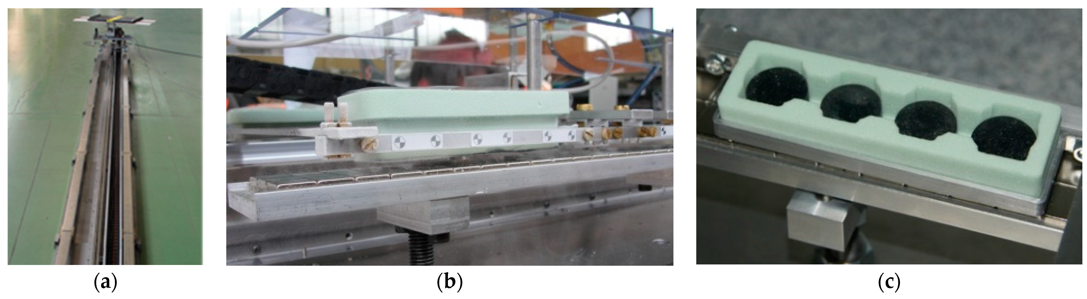
5]. The design of the prototype catapult features magnetic tracks attached to a stationary base, a levitating takeoff platform, and a linear drive (
Figure 1a). During the UAV takeoff, it is mounted on the takeoff platform, which is an integral part of the cart made of a duralumin frame and supported on four supports (
Figure 1b), in which high-temperature YBCO superconductors are placed (
Figure 1c). After cooling the YBCO with liquid nitrogen, the takeoff cart lifts off and levitates above the source of the magnetic field.
One undeniable advantage of this solution is its simple design, which facilitates the transportation and installation with just two personnel required for operation. Moreover, this solution incorporates all the advantages of electromagnetic launchers, allowing for the adjustment of the launch cart speed and acceleration to minimize the applied overload on the aircraft during takeoff. An additional benefit of this solution is the ability to utilize the system for the landing of the UAV, a feature that conventional or coil launchers cannot guarantee.
At the end of the GABRIEL project, tests were carried out on the designed unmanned aerial vehicle in Aachen for takeoff and landing. The tests were successful [
6], but technical issues were encountered, such as the slowly damped vibrations of the cart and the loss of its stable position after disconnecting the linear drive. These issues served as inspiration for further research on the innovative magnetic catapult project.
This article presents numerical studies of the motion of the cart and the catapult system during the UAV launch under varying atmospheric conditions based on a developed model of the dynamics of the launch cart. An important aspect of the research was the experimental determination of the magnetic levitation force as a function of the gap generated by the superconductors.
2. The Model of the Launch Cart for a Magnetic Launcher
In this study, a mathematical model of the launch cart for the magnetic launcher was developed. This model takes into account key factors, such as the characteristics of the environment and the individual components of the launcher, which include the magnetic tracks and the cart that launches the UAV. To further describe and understand the system, various coordinate systems were introduced, which are shown in
Figure 2.
An inertial system (O
fx
fy
fz
f) was firmly tied to the surface of the Earth, providing a fixed reference point. The magnetic system (O
mx
my
mz
m) is used to describe the distribution of the magnetic field and the levitation force. This system is aligned with the symmetry axis of the launcher tracks. The cart system (O
sx
sy
sz
s) is aligned with the longitudinal symmetry axis of the cart and illustrates the direction of the cart’s movement. More detailed descriptions of these reference systems, along with a thorough analysis of the physical model and external influences, can be found in the referenced paper [
7].
The dynamics of the launch cart for a magnetic launcher, which moves in three-dimensional space, is described by a system of mutually coupled nonlinear ordinary differential equations. These equations were derived for the launch cart modeled as a rigid body with six degrees of freedom, using the principle of momentum and angular momentum conservation. The mathematical model of the launch cart’s motion dynamics was thoroughly developed in [
8], and its main stages were discussed in the article [
9]. The formalism for writing the equations of motion is based on a precisely defined method of indexing vector quantities and the properties of rotation matrices, particularly the representation of the derivative of the rotation matrix using a skew-symmetric matrix. The final form of the equations of motion is written in a local, moving reference frame associated with the launch cart O
sx
sy
sz
s. The matrix form of the equations of motion is given by Formula (1). The first equation describes the relationship between the three-dimensional vector of forces acting on the system and the vector of change in the body’s momentum. The second equation maps the vector of force moments to the vector of change in angular momentum.
where:
is a 3 × 3 identity matrix,
is the mass of the launch cart,
is the inertia tensor of the cart,
is the skew-symmetric tensor of the displacement vector of the cart’s center of mass,
is the linear acceleration of the cart,
is the angular acceleration of the cart,
is the angular velocity of the cart,
and
are the forces and moments acting on the cart.
The launch cart levitating above magnetic tracks is subject to magnetic forces and moments of force
,
, aerodynamic forces and moments of force
, gravitational forces and moments of force
,
as well as the propulsion force from the linear motor
; therefore, the resulting force vector and moment of force have the following form
The mathematical model of the cart should be supplemented with kinematic relationships describing its angular velocity
and linear velocity
, as well as a geometric relationship describing the vector between the local coordinate system of the cart and the inertial coordinate system
.
where
is the rotation matrix describing the orientation of the inertial frame relative to the local frame of the cart.
The described mathematical model of the launch cart provides a basis for further research on its dynamic properties, including the numerical analysis of its motion. These studies were preceded by an analysis of the acting forces. The process of the theoretical modeling of forces and moments acting on the launcher system was discussed in detail in [
7]. The analyses presented there indicated interactions between the loads and their influence on the UAV launch process. The key role is played by the magnetic levitation force. Its experimental identification process is included in
Section 3.
3. Experimental Identification of Magnetic Levitation Force
The levitation force, which lifts the launcher cart above the magnetic tracks, is caused by the Meissner effect [
10]. The Meissner effect is a phenomenon in which a superconductor expels magnetic field lines from its interior. It has been studied in various applications, including Maglev trains and energy storage systems [
11,
12], as well as in the context of superconducting materials used in aerospace engineering, such as in the development of high-performance motors and generators [
13].
In the analyzed magnetic launcher, the levitation force is a result of the Meissner effect occurring between the tracks of the magnetic rails and the superconductors enclosed in containers—supports of the launch cart. After filling the supports with liquid nitrogen, the superconductors transition into the superconducting state, and as a result of the Meissner effect, they begin to levitate above the tracks.
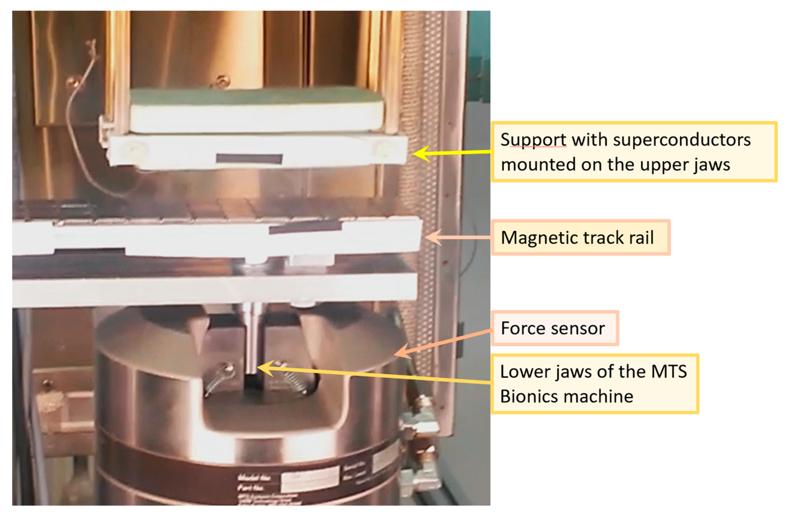
To identify the value of magnetic levitation force, a measurement experiment was carried out using the MTS Bionics testing machine. A section of the magnetic track rail was attached to the lower, stationary jaws of the machine, and a support with four YBCO superconductors was mounted on the upper jaws (
Figure 3).
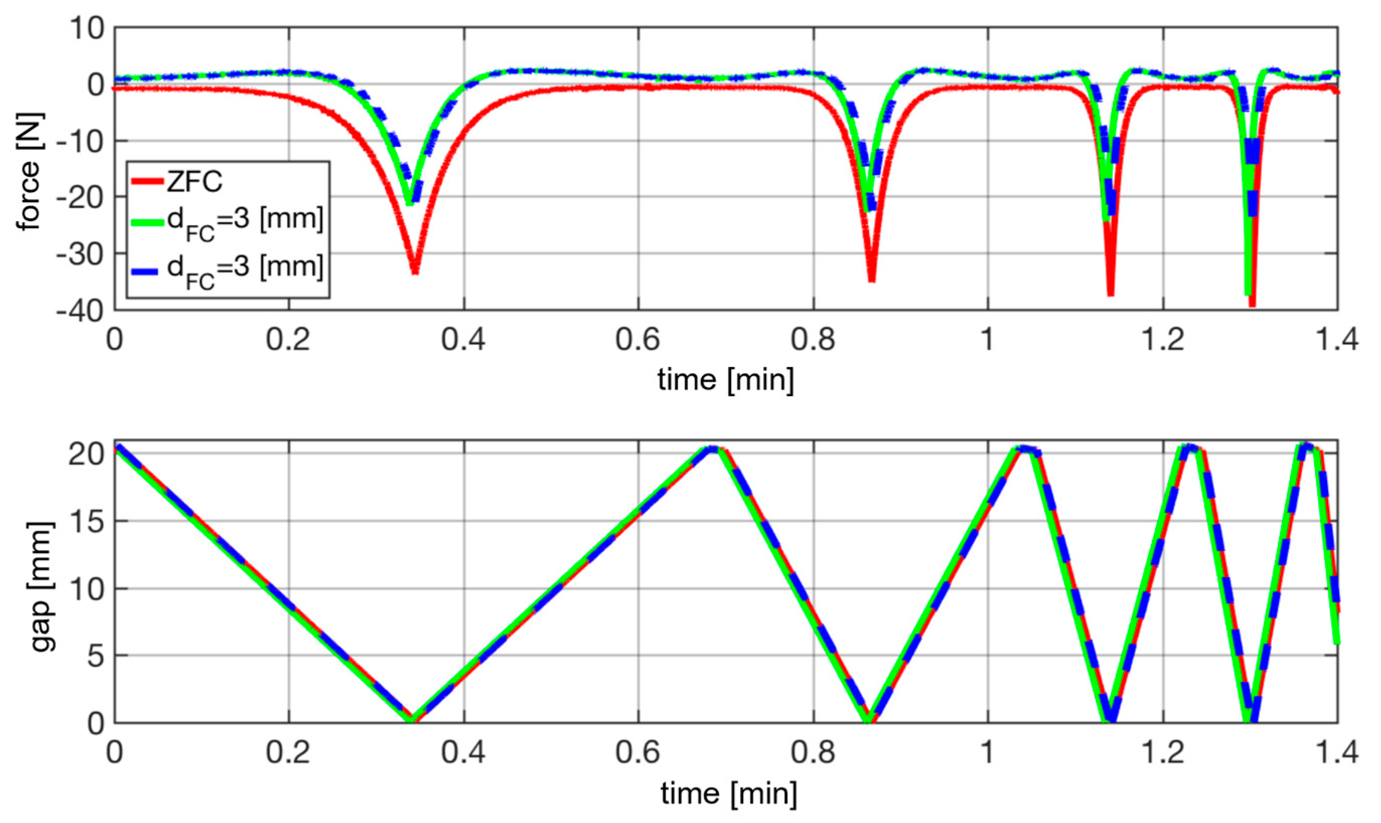
Figure 4 presents the results of measurements aiming to determine the effect of the levitation gap height on the value of the magnetic levitation force. In the first series of measurements (red line), the superconductors were cooled with liquid nitrogen at a height of 20 mm above the magnets, where the magnetic field has zero value (ZFC—zero field cooling). Such a superconductor is only affected by the magnetic force resulting from the Meissner effect. In the second series of measurements, the superconductors were cooled with liquid nitrogen in a non-zero magnetic field at a height of 3 mm above the magnets (d
FC = 3 mm). The measurements were repeated twice (blue and green lines), which showed the convergence of the obtained results. The upper graph shows the levitation force value registered by the force sensor of the strength machine, while the lower graph shows the size of the levitation gap, i.e., the distance between the levitating support and the launcher rails.
The conducted observations of the superconductor’s behavior in a magnetic field showed that the levitation force value is a function of the levitation gap (distance of the superconductor from the magnetic field). Additionally, in the case of filling the superconductor with liquid nitrogen in a non-zero magnetic field, the maximum recorded value of the levitation force is almost half the value obtained when filling the superconductor in the zero magnetic field. This confirms the fact that there are two forces acting on the superconductor: a force repelling the superconductor from the source of the magnetic field, resulting from the Meissner effect
, and a force attracting the superconductor to the source of the magnetic field, resulting from the flux pinning effect
.
As a result of the flux pinning phenomenon, the superconductors placed inside the supports of the cart become magnetized [
14]. The widely used advanced mirror-reflection method [
15] for modeling magnet–superconductor interactions suggests that the levitation force can be expressed by the following equation [
16].
where
B is the external magnetic field and
m is the vector of the magnetic moment frozen within the superconductor at the moment of the phase transition.
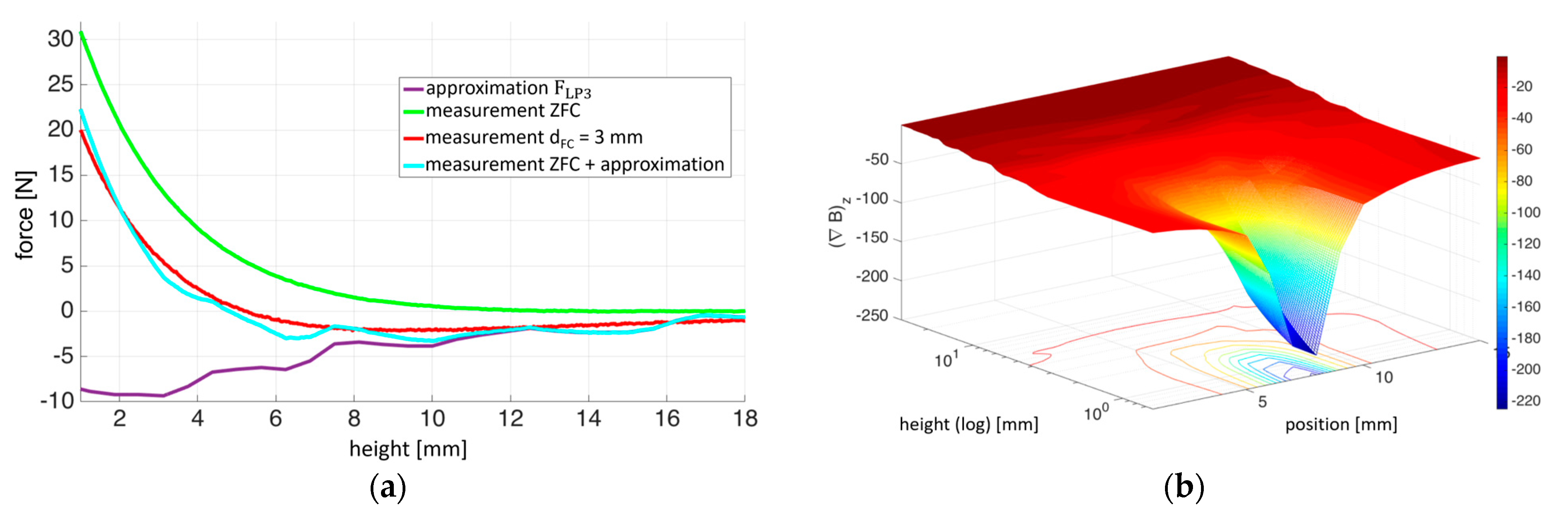
The approximating functions for the levitation forces used in the numerical model are presented in
Figure 5a. The green and red lines indicate the experimentally measured levitation force. The green line corresponds to the superconductor being cooled with liquid nitrogen in a zero magnetic field (
, while the red line represents the case where the superconductor is cooled with liquid nitrogen at a height of 3 mm. Thus, the red line represents the sum of the force resulting from the Meissner effect (green line) and the force arising from the flux pinning phenomenon.
At a height of 5.2 mm, the force resulting from the Meissner effect (with a value of 5.4 N) and the force resulting from flux pinning balance each other. By determining the value of the magnetic field gradient along the vertical axis at a height of 5.2 mm (with an absolute value of ∇
20.6 N/T) (
Figure 5b) based on finite element analysis [
12], the induced magnetic moment in the superconductor was calculated to be
0.26 T using Equation (8). Thus, knowing the value of
m, the force resulting from flux pinning was approximated when the superconductors were immersed in liquid nitrogen at a height of 3 mm (purple line).
The light blue line was obtained by summing the measurements of the levitation force when the superconductor was immersed in liquid nitrogen under zero magnetic field conditions (green line) and the approximated force resulting from flux pinning (purple line). Similarly, the force acting on the superconductor immersed in liquid nitrogen at any height can be approximated using a similar approach.
The identification of the magnetic levitation force provided a basis for further numerical studies of the magnetic launcher system. The results of the numerical simulations of the longitudinal and lateral motion of the cart as well as the configuration of the UAV–cart system during UAV launch under variable atmospheric conditions are presented below.
4. Numerical Studies of the Dynamics of the Launch Cart in a Launcher
The computer program designed for the analysis of dynamics and the visualization of the trajectory of the launch cart was implemented in MATLAB. The simulation model was formulated as an initial value problem of ordinary differential equations based on the mathematical model discussed above.
Two simulation scenarios were demonstrated, encompassing:
Longitudinal motion of the launch cart, where the center of mass of the cart only moves in the vertical plane.
Transverse motion, considering both longitudinal and the lateral displacement of the cart from the center of the tracks in the transverse direction.
The longitudinal motion of the launch cart is generated by the linear motor. In the GABRIEL technology demonstrator, which was designed as part of the project, the motor stator is mounted in the middle of the magnetic tracks, and its structure restricts the lateral movements of the cart [
17]. Therefore, in the simulation analyses of the investigated launcher system, the omission of the lateral movements of the launch cart is fully justified. In the second simulation, the behavior of the cart was additionally analyzed when it is detached from the motor stator, taking into account the effects on its motion in space caused by the trapping of magnetic flux inside the superconductors.
The authors’ intention was to conduct numerical analyses based on a nonlinear model of the launch cart’s dynamics, described by Equations (1)–(6). Therefore, the analysis of these simulation scenarios is a result of applying initial conditions and physical relationships derived from modeling the forces acting on the system.
In both presented simulation scenarios, it was assumed that the launcher tracks are in a horizontal position. The simulation time was 2 s. During the first second, the launch cart is driven by a constant force of 20 N, while during the second s, the cart is braked and the propulsion force changes direction.
4.1. Longitudinal Motion of the Cart
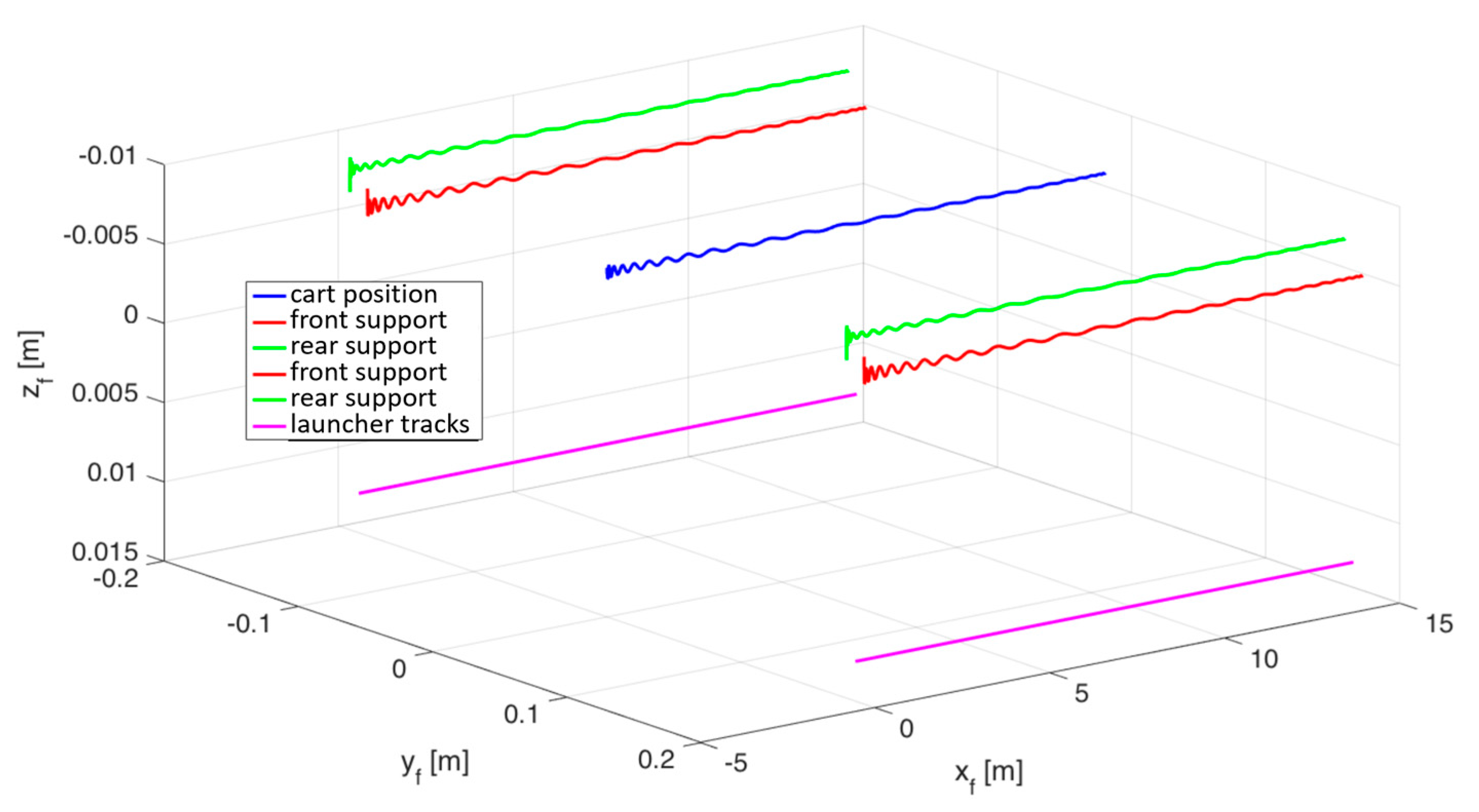
In the presented simulation scenario, the behavior of the cart was investigated, where its center of mass is consistently located on the axis of symmetry of the tracks, but it does not coincide with the geometric center. It was assumed that the center of mass of the cart was displaced along the
xs longitudinal axis by
. At the initial time, the cart is located at a height of
. Due to the displacement of the center of mass, the cart is subjected to the gravitational moment of force. The unbalanced moment of force causes the cart to tilt around the
ys lateral axis. The difference in height between the front and rear supports of the cart results in a different value of levitation forces exerted on individual supports. As a result, a moment of force is created that balances the gravitational moment of forces and stabilizes the orientation of the cart.
Figure 6 shows the trajectory of the cart. The blue line represents the motion of the center of the cart, the purple line marks the position of the launch rails, while the green and red lines visible on the left and right reflect the position of the cart supports. It can be seen that the cart has tilted forward and the front supports are lower than the rear supports.
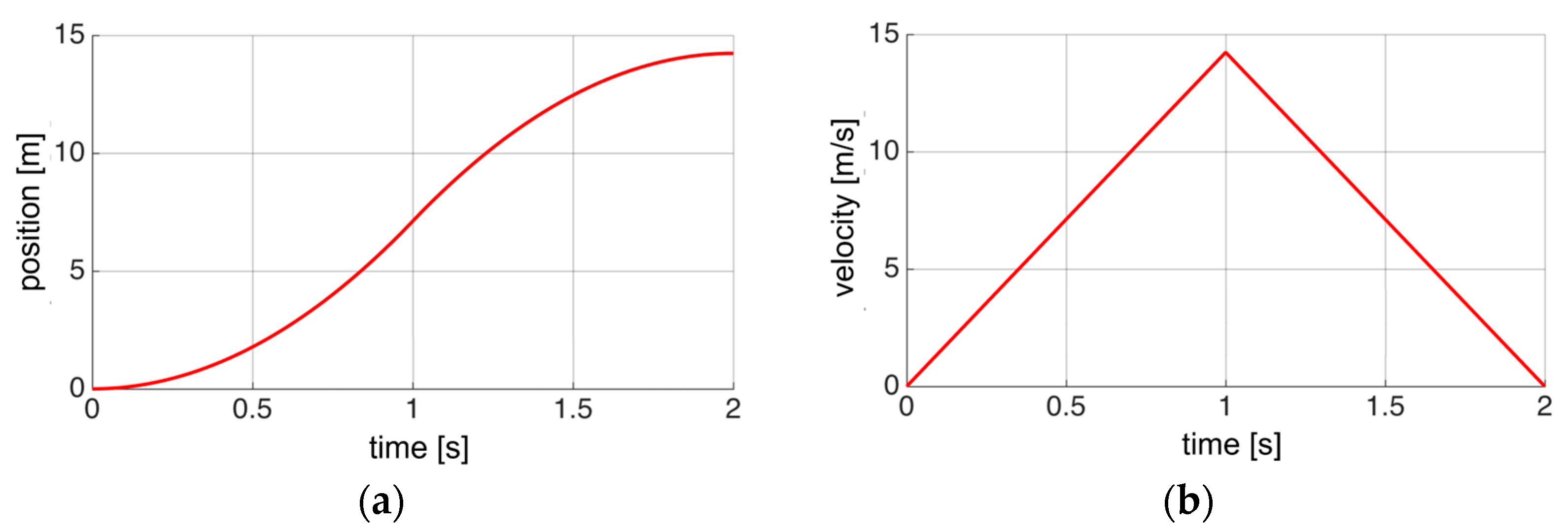
After 2 s, the cart traveled a distance of 14.2 m (
Figure 7a) and reached a maximum speed of 14 m/s, and then came to a stop (
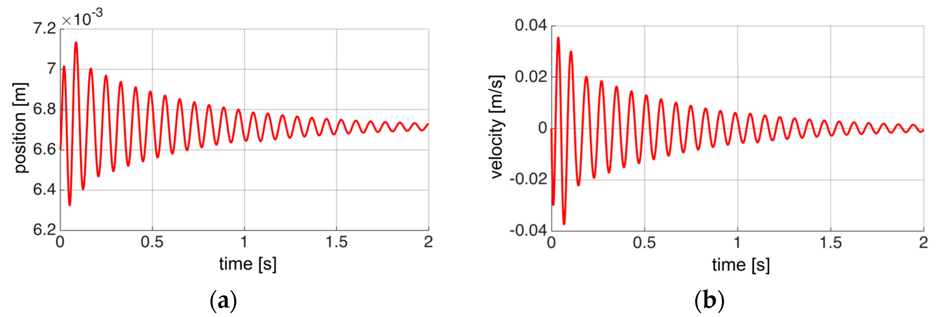
Figure 7b). The simulation showed small vibrations of the cart (
Figure 8a) around the equilibrium position. The vertical velocity of the cart oscillates within ±0.0035 m/s (
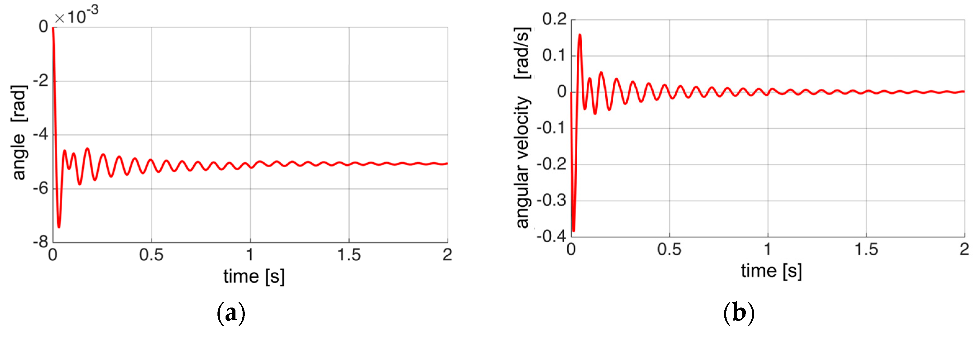
Figure 8b). The tilt angle of the cart stabilizes at −0.005 rad (
Figure 9a), and then its angular velocity decreases to zero (
Figure 9b).
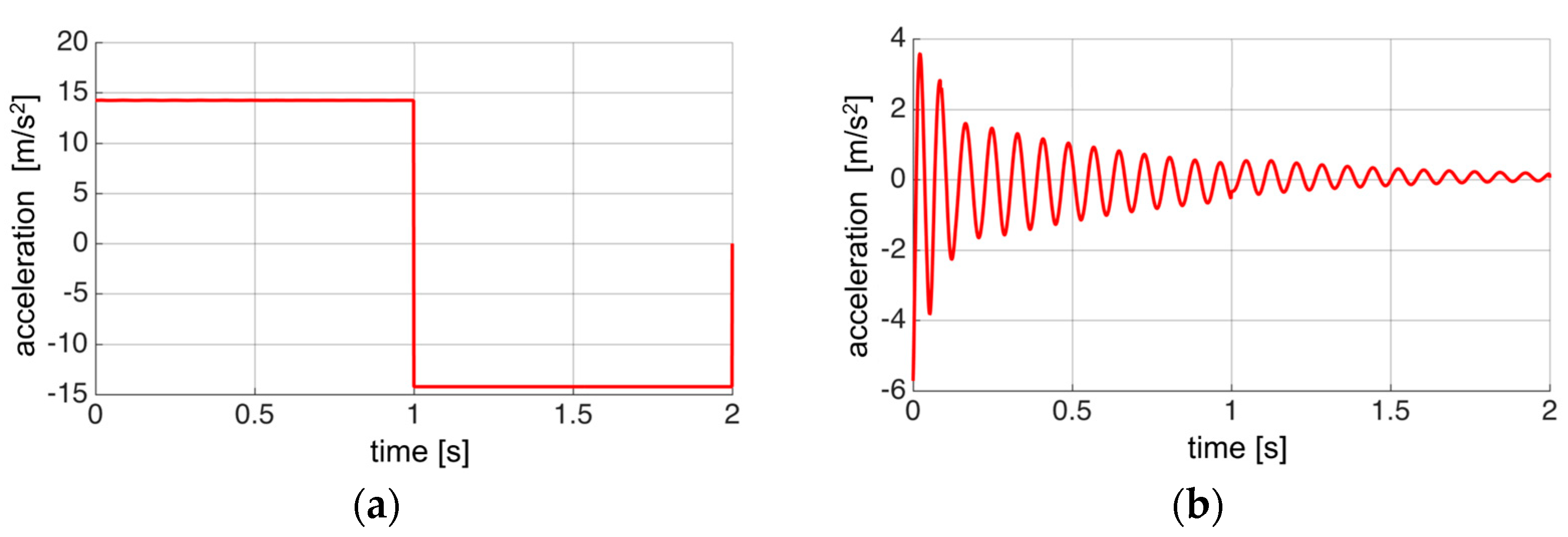
Powered by a linear motor, the cart moves with a constant horizontal acceleration of 14.2 m/s
2 during the first second, and then decelerates with the same magnitude of acceleration (
Figure 10a). The vertical acceleration component oscillates around zero (
Figure 10b). The vibrations are related to the cart’s stabilization around the equilibrium position.
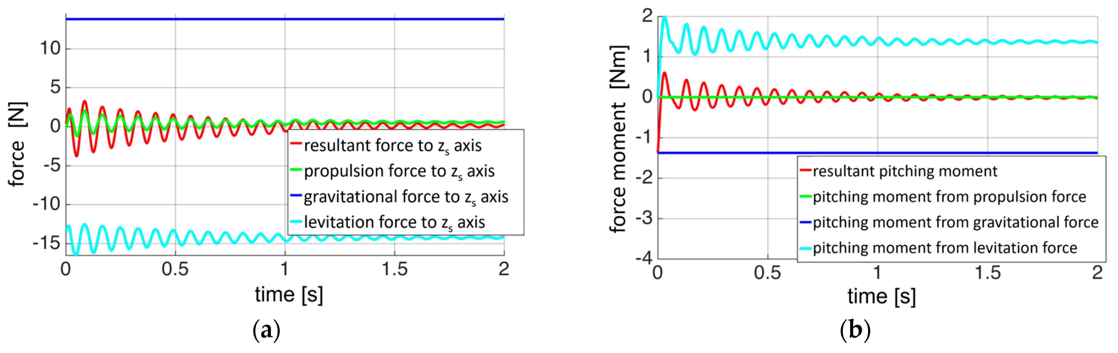
The launch cart tends towards the equilibrium position (
Figure 11). The gravity and levitation forces components along the longitudinal axis having opposite values. The oscillations are slowly damped, which is a characteristic feature of the magnetic suspension of the launcher.
The results of the conducted simulations indicate that the equilibrium point at which the weight of the cart is balanced by the levitation force is 6.6 mm; the maximum height to which the cart rises due to the action of the levitation force is 7.16 mm; shifting the center of mass of the cart in the x axis direction results in a non-zero tilting moment, balanced by the moment of forces resulting from the difference in the value of the levitation force acting on the front and rear supports of the cart. The simulation studies confirmed that a characteristic feature of the launcher suspension is the low damping of vibrations, which was demonstrated in experimental studies [
7].
An important attribute that distinguishes the levitation launcher from other unmanned aircraft launchers is the maintenance of a constant acceleration value for the launch cart during takeoff (
Figure 10), ensuring a consistent acceleration throughout the entire runway. It is worth emphasizing that the value of this acceleration can be easily controlled by increasing or decreasing the thrust force of the linear motor.
4.2. Lateral Motion of the Cart
In the next simulation, the motion of the cart detached from the linear motor was considered, with its center of mass shifted by 2 mm along the lateral axis of the magnetic tracks. The simulation took into account the forces resulting from the phenomenon of flux trapping inside the superconductor.
It was assumed that the superconductor was immersed in liquid nitrogen at a height of dFC = 3 mm, similarly to the experiments described in Chapter 3. The superconductor is then subject to the resultant force FLs described by Equation (7), as well as a torque aiming to align the magnetic moment vector of the superconductor with the external magnetic field induction vector.
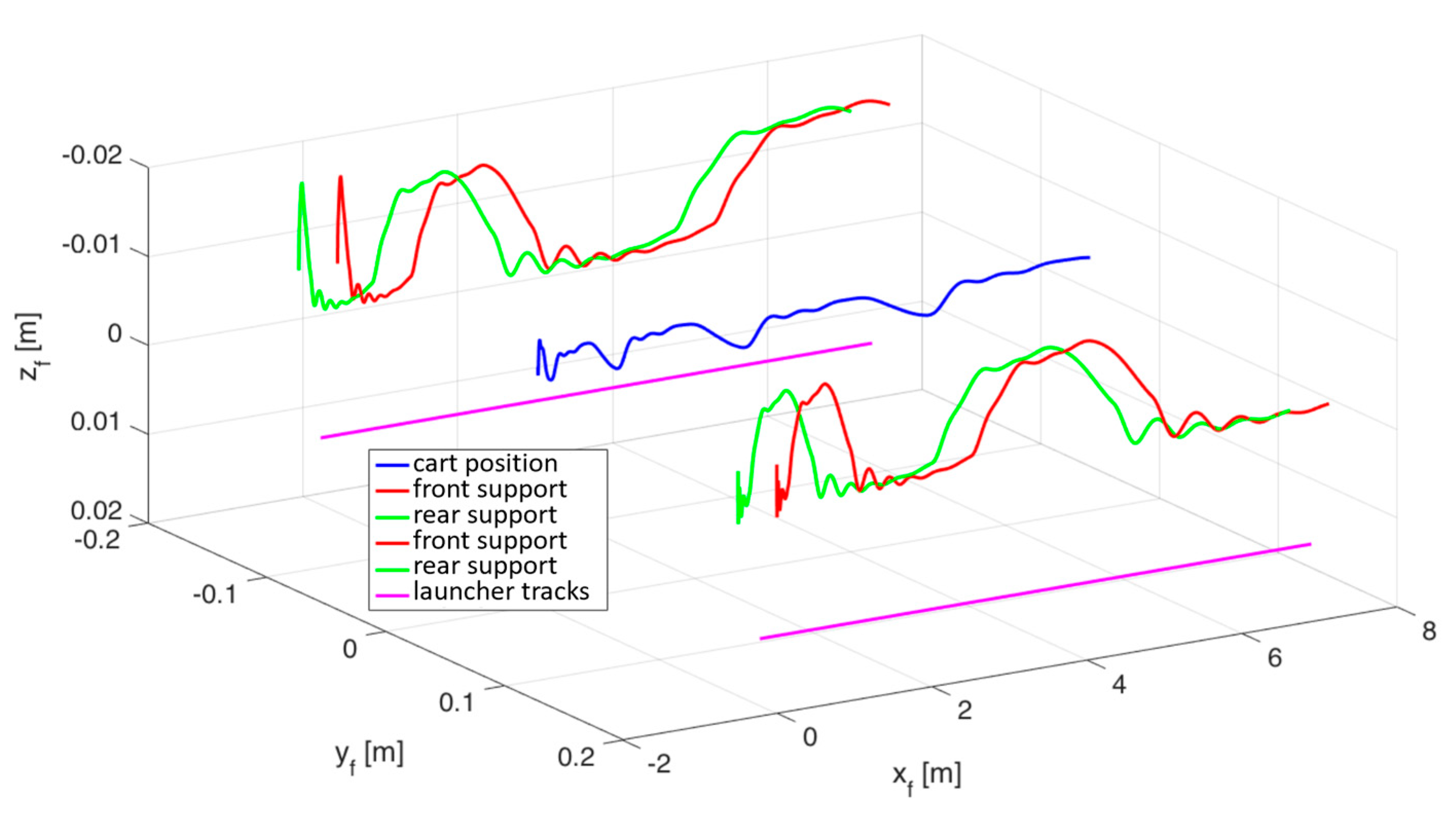
The trajectory of the cart’s motion is shown in
Figure 12. When detached from the motor stator, the cart moves along the rails of the launcher in a weakly damped periodic motion. The oscillations of the left and right supports are synchronized in antiphase, aiming to maintain the center of mass of the cart aligned with the center of the magnetic rails.
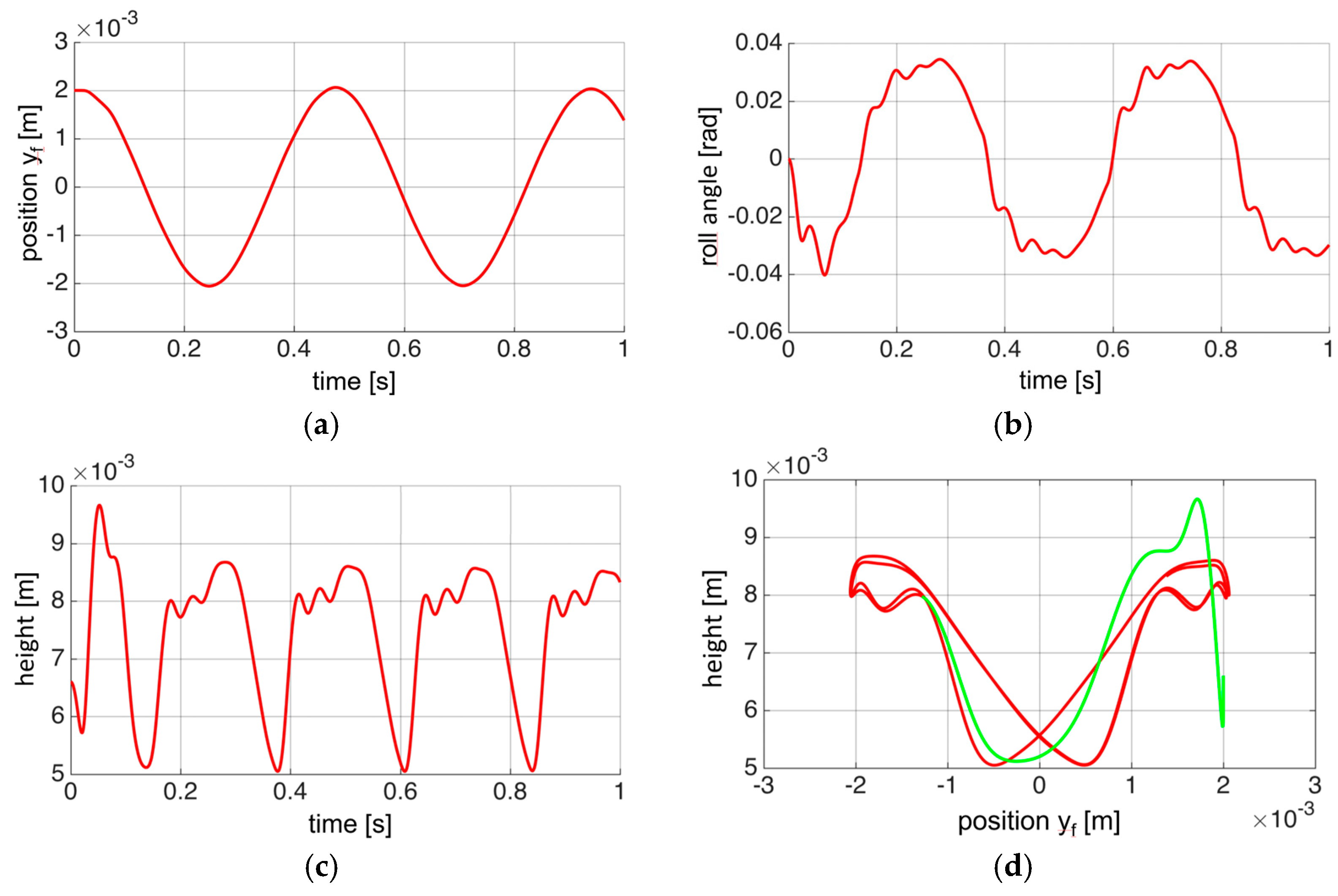
Figure 13 shows the course of the position and orientation components of the cart. It can be seen that the cart was set in an undamped vibrational motion relative to the center of the launcher tracks (
Figure 13a). In the simulations, the oscillations of the cart deflection angle (around the
xf axis) were observed (
Figure 13b), which explains the spatial trajectory behavior (
Figure 12)—at the moment when the right supports of the cart are the highest, the left supports reach the lowest position, and then the situation is reversed. The cart oscillations along the longitudinal
xf and lateral
yf axes are synchronized and are in antiphase. The oscillation period is 0.45 s, and the amplitude of lateral motion is 2 mm. The maximum tilt of the cart in periodic motion is 0.033 rad. As the cart moves away from the center of the rails, its height increases (
Figure 13c). At zero displacement of the cart along the
yf axis, its height is 5 mm, which is smaller than the equilibrium point determined for a cart solely subjected to the Meissner levitation effect.
Figure 13d shows the height of the cart as a function of the displacement of the cart along the lateral axis
yf. The green line marks the trajectory during the first 0.18 s, when the motion of the cart is aperiodic. After that, the cart is set in periodic vibrations marked on the graph in red. The graphs show clear nonlinearity and hysteresis of the cart motion.
Based on simulation studies, it was found that the unpowered launch cart, when its center of mass is slightly shifted, does not return to its equilibrium position. The cart vibrations are not damped. This shows that the lateral motion of the cart is very unstable and requires additional position stabilization, e.g., using a linear motor.
5. Numerical Investigations of the UAV Launch Process from a Launcher
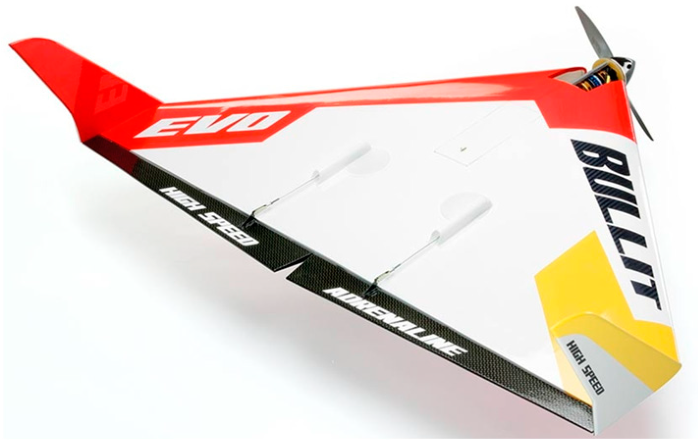
The complement to the analyzed dynamics of the magnetic launcher cart is the analysis of the process of the UAV uncontrolled takeoff, which was conducted taking into account the influence of disturbances resulting from air movements in the form of constant wind and gusts. The test UAV considered was a Bullit airplane (
Figure 14). The aerodynamic model of the UAV [
18] was examined. The main data of the analyzed UAV are gathered in
Table 1.
According to the takeoff procedure developed within the GABRIEL project, the aircraft is mounted on the launch cart prior to takeoff. A linear motor is used to accelerate the cart. When the system reaches the separation speed, the aircraft is detached from the cart and continues its independent flight.
The numerical simulations were conducted assuming that, at the initial moment, the UAV is located on the launcher cart above the tracks, and the aircraft’s propulsion is turned off. The motion of the system is initiated by the launcher cart, which is accelerated by a force of 50 N. The takeoff is performed with the UAV’s propulsion turned off. In the developed numerical model, the couplings between the cart and the UAV starting from it were analyzed, taking into account the influence of constant headwind and tailwind, as well as gusts on the process of the UAV takeoff from the magnetic launcher.
5.1. Takeoff of UAV in Calm Atmosphere and with Headwind or Tailwind
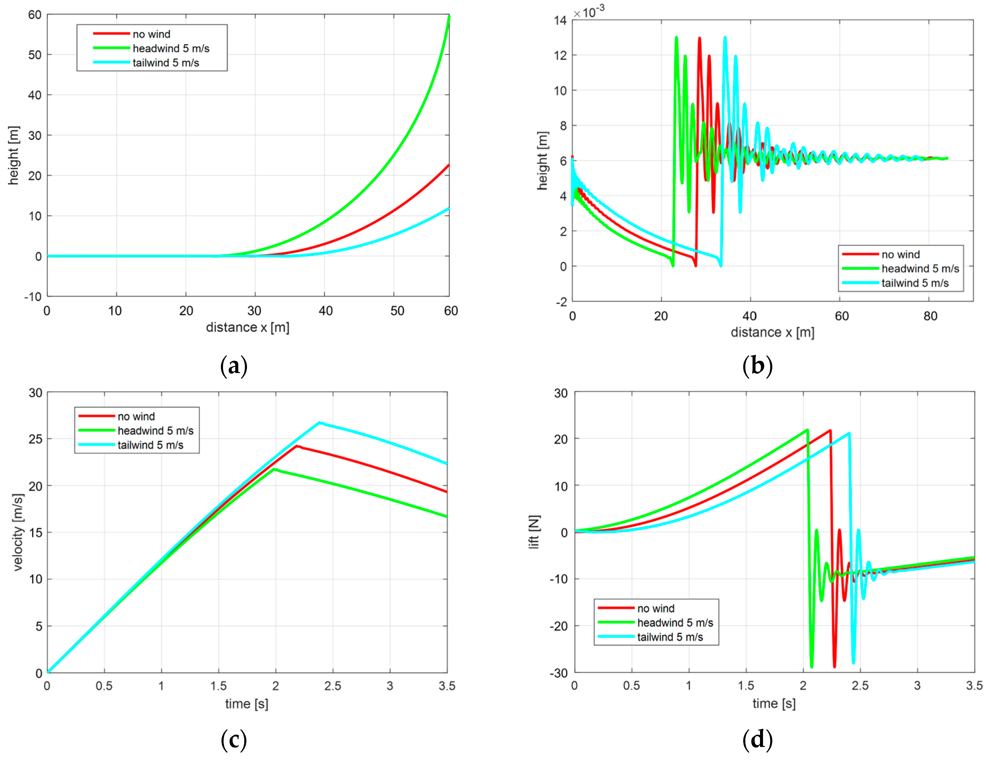
In the conducted numerical simulation analyses, the results of modeling the UAV takeoff process were compared under calm atmospheric conditions, and then with the consideration of a constant headwind or tailwind blowing at a speed of 5 m/s.
The motion parameters of the launcher cart and the UAV taking off from it in calm air are presented in
Figure 15 by a solid line. In this case, the UAV separation occurs at t = 2.2 s with a speed of 24 m/s after covering a distance of 28 m from the cart. The headwind shortens the UAV takeoff distance, while the tailwind lengthens it, as shown in
Figure 15a. This is caused by a faster increase in the lift force in the case of headwind (
Figure 15d). The separation velocity measured in the inertial system will then be lower (
Figure 15c). During the climbing phase, the UAV without propulsion loses its speed.
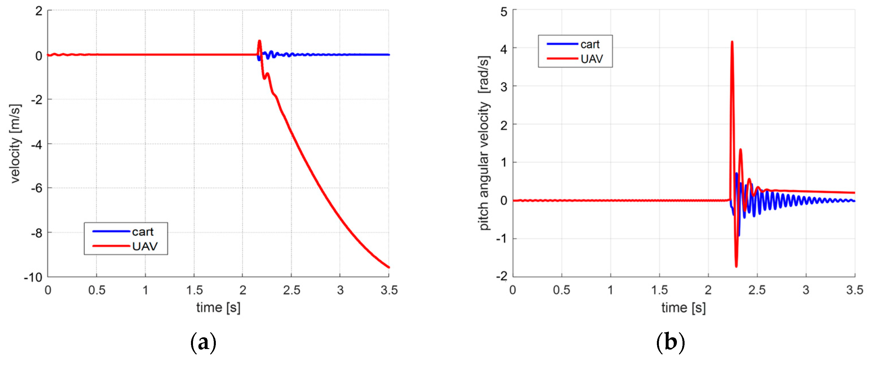
The mutual interaction between the motions of the starting cart and UAV is shown in
Figure 16. After the UAV leaves the launcher, the oscillations of the velocities of both elements of the system are visible, with the high-frequency oscillations of the velocity vector of the starting cart being damped much more slowly. This is a characteristic feature of magnetic suspension, which has been confirmed in experimental studies [
6].
5.2. Gust Impact on UAV Takeoff
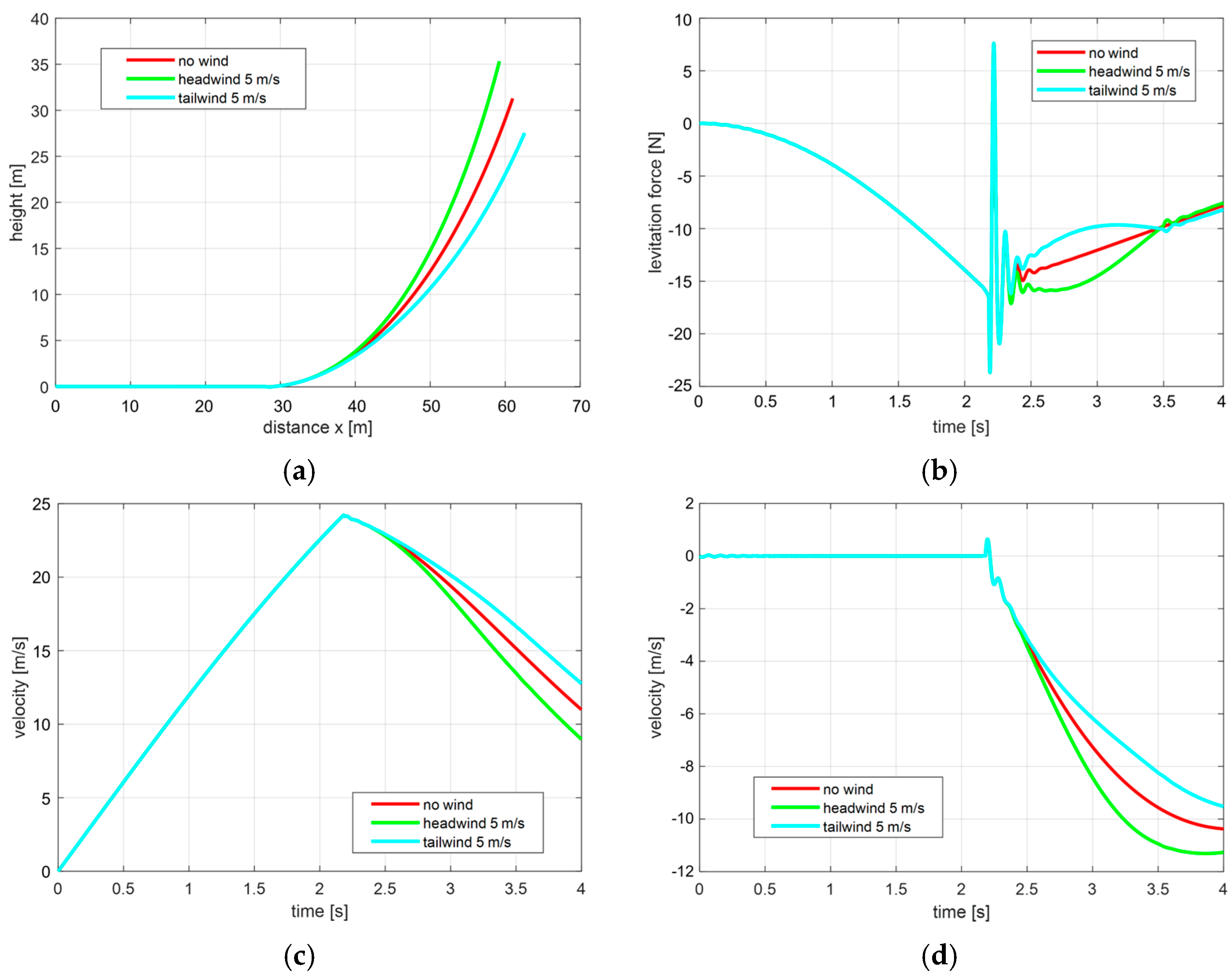
In the analyzed cases of uncontrolled UAV takeoff in a gust, it was assumed that the gust of wind occurs along the horizontal axis and is described by the function
where it was assumed that the wind gust occurs along the horizontal axis and is described by the function, where the gust amplitude
A = 5 m/s, duration
d = 1 s, and the gust onset time
ts = 2.3 s coincides with the moment of UAV detachment from the launcher.
On
Figure 17, the results of the analysis of the start without wind are compared with the results of the start with variable head and tailwinds. The simulations conducted show the effect of the gust on the change in UAV trajectory and speed. The headwind causes the UAV speed relative to the ground to decrease. Conversely, in the case of tailwind, its speed relative to the ground increases (and at the same time, the aerodynamic speed decreases), which in special cases can lead to exceeding the critical angle of attack.
During the analyzed gust, the kinematic parameters of the launching cart do not change because the gust starts at the moment when the UAV departs from the launcher. However, it does affect the dynamics of the cart, as shown by the levitation force graphs (
Figure 17b). During the gust, the levitation force increases or decreases its value in a manner analogous to the function of the wind speed change.
In the conducted numerical analyses, the relationship between the wind and the motion parameters of the UAV launch system was shown. The impact of wind on the parameters of the launch system, such as the trajectory, speed, tilt angle, and angular velocity, as well as the lift force of the launch cart, was examined. Compared to the trajectory without wind, headwind shortens the takeoff distance while the tailwind lengthens it. The results of the conducted numerical studies confirm the correctness of the developed mathematical model, demonstrating that the design of the analyzed launcher enables a safe takeoff. Based on these results, the optimal parameters for the magnetic launcher system can be selected. Primarily, the dimensions of the magnetic rails must correspond to the size of the launching UAV, ensuring that the generated levitation force is capable of lifting it. Therefore, in the analyzed simulation cases, the Micro UAV Bullit was taken into consideration.
6. Conclusions
The article describes the process of modeling and analyzing the dynamic properties of the launch cart of an innovative prototype of an unmanned aircraft launcher utilizing passive magnetic suspension with high-temperature superconductors. The aim of modeling the dynamics of the launch cart of the analyzed launcher, constructed as part of the GABRIEL project, was to specify the operating conditions of the system. Two types of cart motion were analyzed. In the first case, the motion of a cart driven by a linear motor, which constrains lateral movements, was considered. Then, the behavior of the driven cart detached from the motor stator was analyzed, allowing for the examination of the spatial behavior of the cart on the launcher rails, taking into account its lateral movements and the influence of forces resulting from magnetic flux trapping inside the superconductors. Complementing the dynamics analysis of the magnetic launcher’s launch cart were numerical simulations, in which variable atmospheric parameters and couplings resulting from the mutual interaction of individual elements of the launch system were considered. The analysis included the study of the process of uncontrolled UAV launch, taking into account the influence of constant headwind, tailwind, and gusts.
On the basis of the results presented in the paper, the following conclusions can be drawn:
The developed simulation model enables the specification of the operating conditions of the modeled catapult system and analysis of the possibilities of counteracting disturbances.
During the launch, a constant acceleration of the launch cart is maintained, resulting in the UAV’s takeoff process occurring with constant acceleration.
The acceleration value can be easily controlled by adjusting the thrust force of the linear motor, thereby minimizing the applied overload on the UAV.
The suspension system of the launcher exhibits the low damping of vibrations, as reflected in the simulated motion of the launch cart and confirmed by the vibrations of the cart support recorded during the field tests of the launcher [
6,
7].
The simulations indicate that, for the analyzed system parameters, the equilibrium point where the cart mass is balanced by the levitation force is located at 6.6 mm, and the maximum height to which the unloaded cart rises due to the levitation force is 17.3 mm.
Displacement of the carts’ center of mass along the longitudinal axis results in nonzero tilting moments, which are balanced by the differential levitation force acting on the front and rear cart supports. However, this equilibrium is lost when the displacement of the carts’ center of mass along the longitudinal axis exceeds 16 cm, causing the destabilization of the carts’ orientation and leading to an impact upon the launcher rails.
Lateral motion of the cart is unstable and requires additional position stabilization, such as through the use of a linear motor, as demonstrated in the GABRIEL project’s launch tests and confirmed by numerical simulations.
Displacement of the carts’ center of mass relative to the transverse axis of the rails by less than 5.4 mm induces weakly damped harmonic vibrations with respect to the center of the rails, while larger displacements cause the cart to derail from the launcher rails.
Compared to the windless trajectory, headwind shortens the takeoff run (as the profile moving into the wind can generate greater lift force), while tailwind lengthens it, simultaneously increasing ground speed.
Tailwind reduces the UAV’s aerodynamic speed, which can, in certain cases, lead to exceeding the critical angle of attack.
The levitation force adjusts its value proportionally to the wind speed changes.
The results of the conducted numerical studies confirm the correctness of the developed mathematical model and demonstrate that the design of the analyzed launcher enables a safe takeoff.
The analyzed launcher is an innovative alternative to the available market options for unmanned aircraft launchers. The developed mathematical and numerical model, enabling the simulation of the launch cart’s motion on the launcher rail during the takeoff and landing of the UAV, indicates that the design of the analyzed launcher allows for a safe takeoff under variable weather conditions. The longer takeoff path provided by the launcher reduces the overload on the UAV during takeoff, resulting in increased safety for the launcher, aircraft, and onboard equipment. Any vibrations of the UAV system, caused by uneven mass distribution or external factors, are dampened by the magnetic forces and moments arising from the Meissner effect and the trapping of magnetic flux within the superconductors.
The most significant advantage of electromagnetic launchers, especially magnetic levitation launchers, is the reduction in acceleration and its constant value during takeoff. Conventional catapults are characterized by very high accelerations during takeoff, which can damage the aircraft and equipment. Due to the fact that, in levitation launchers, the aircraft is accelerated at a constant acceleration throughout the entire length of the runway, the takeoff process is very smooth. It should be emphasized that the value of this acceleration can be easily controlled.
Author Contributions
Conceptualization, E.Ł.-K., K.S. and A.S.-M.; methodology, E.Ł.-K., A.S.-M. and K.S.; software, A.S.-M. and D.P. validation, E.Ł.-K., D.P. and A.S.-M.; formal analysis, E.Ł.-K. and A.S.-M.; investigation, A.S.-M., D.P. and E.Ł.-K.; resources, K.S. and A.Ż.; data curation, K.S. and A.Ż.; writing—original draft preparation, E.Ł.-K.; writing—review and editing, E.Ł.-K., K.S. and A.S.-M.; visualization, A.S.-M.; supervision, E.Ł.-K. and K.S.; project administration, E.Ł.-K.; funding acquisition, E.Ł.-K. and A.Ż. All authors have read and agreed to the published version of the manuscript.
Funding
Research was funded by the Warsaw University of Technology within the Excellence Initiative: Research University (IDUB) program. The APC was funded by Air Force Institute of Technology.
Data Availability Statement
Data supporting reported results are contained within the article.
Conflicts of Interest
The authors declare no conflict of interest.
References
- Westinghouse Eng. A Wound Rotor Motor 1400 Feet Long. 1946, Volume 6, pp. 160–161. Available online: https://www.theengineer.co.uk/october-1946-westinghouse-unveils-the-electropult/ (accessed on 11 May 2023).
- Patel, A.; Hopkins, S.C.; Baskys, A.; Kalitka, V.; Molodyk, A.; Glowacki, B.A. Magnetic levitation using high temperature superconducting pancake coils as composite bulk cylinders. Supercond. Sci. Technol. 2015, 28, 115007. [Google Scholar] [CrossRef]
- Schultz, L. Interaction of Ferromagnetic and Superconducting Permanent Magnets: Basics and Applications of Passively Stable Quantum Levitation. In Sustainable Industrial Processing Summit SIPS2019; Kongoli, F., Calin, M., Dubois, J.M., Zuzek-Rozman, K., Eds.; Flogen Star OUTREACH: Mont Royal, QC, Canada, 2019; Volume 3, pp. 38–39. [Google Scholar]
- Magnetic Take-Off and Landing for Fuel-Efficient Aircraft. Available online: https://cordis.europa.eu/article/id/92581-magnetic-takeoff-and-landing-for-fuelefficient-aircraft (accessed on 11 May 2023).
- Sibilski, K.; Falkowski, K.; Kaleta, R.; Ładyżyńska-Kozdraś, E.; Anna Maria Sibilska-Mroziewicz, A.; Wróblewski, W. Development of the Small-Scale Model of Maglev System Assisted Aircraft Safety Take-Off and Landing. In Proceedings of the 30th ICAS Congres (IICAS 2016-0369), Daeion, Republic of Korea, 25–30 September 2016; Available online: https://www.icas.org/ICAS_ARCHIVE/ICAS2016/data/papers/2016_0359_paper.pdf (accessed on 11 May 2023).
- Ładyżyńska-Kozdraś, E.; Sibilska-Mroziewicz, A.; Czubaj, S.; Falkowski, K.; Sibilski, K.; Wróblewski, W. Take-off and landing magnetic system for UAV carriers. J. Mar. Eng. Technol. 2017, 16, 298–304. [Google Scholar] [CrossRef] [Green Version]
- Sibilska-Mroziewicz, A.; Ładyżyńska-Kozdraś, E.; Falkowski, K. Modelling of Forces Acting on a System of the UAV Launcher, Based on Passive Magnetic Suspensions with Superconductors. Nase More 2020, 67, 60–68. [Google Scholar] [CrossRef]
- Sibilska-Mroziewicz, A. Opracowanie Modelu Dynamiki Wózka Startowego Wyrzutni Samolotu Bezzałogowego, z Wykorzystaniem Efektu Meissnera. Ph.D. Thesis, Warsaw University of Technology, Warsaw, Poland, 2018. [Google Scholar]
- Sibilska-Mroziewicz, A.; Ładyżyńska-Kozdraś, E. Mathematical Model of Levitating Cart of Magnetic UAV Catapult. J. Theor. Appl. Mech. 2018, 56, 793–802. [Google Scholar] [CrossRef] [Green Version]
- Yaghoubi, H. The most important maglev applications. J. Eng. 2013, 2013, 537986. [Google Scholar] [CrossRef] [Green Version]
- Maitreya, S.; Soni, S.; Paliwal, P. Analysis of Electromagnetic Aircraft Launching System for Naval Aircraft. In Technology Innovation in Mechanical Engineering; Chaurasiya, P.K., Singh, A., Verma, T.N., Rajak, U., Eds.; Lecture Notes in Mechanical Engineering; Springer: Singapore, 2022; pp. 773–781. [Google Scholar] [CrossRef]
- Bhatia, D.K.; Aljadiri, R.T. Electromagnetic UAV launch system. In Proceedings of the 2017 2nd IEEE International Conference on Intelligent Transportation Engineering (ICITE), Singapore, 1–3 September 2017; pp. 280–283. [Google Scholar]
- Nusran, N.M.; Joshi, K.R.; Cho, K.; Tanatar, M.A.; Meier, W.R.; Bud’ko, S.L.; Prozorov, R. Spatially-resolved study of the Meissner effect in superconductors using NV-centers-in-diamond optical magnetometry. New J. Phys. 2018, 20, 043010. [Google Scholar] [CrossRef]
- McHenry, M.; Sutton, R. Flux pinning and dissipation in high temperature oxide superconductors. Prog. Mater. Sci. 1994, 38, 159–310. [Google Scholar] [CrossRef]
- Kordyuk, A. Magnetic levitation for hard superconductors. J. Appl. Phys. 1998, 83, 610–612. [Google Scholar] [CrossRef]
- Sibilska-Mroziewicz, A.; Ładyżyńska-Kozdraś, E.; Falkowski, K.; Sibilski, K. Estimation of the force causing the levitation of the starting trolley of the unmanned aerial vehicle. Bull. Pol. Acad. Sci. Tech. Sci. 2020, 68, 1177–1185. [Google Scholar] [CrossRef]
- Sibilska-Mroziewicz, A.; Ładyżyńska-Kozdraś, E.; Sibilski, K. VR-Supported Analysis of UAV—Magnetic Launcher’s Cart System. Energies 2023, 16, 4095. [Google Scholar] [CrossRef]
- Mystkowski, A.; Ostapkowicz, P. Weryfikacja modelu dynamicznego mikro-samolotu z wibrującymi generatorami wirów do sterowania przepływem. Prace. Inst. Lotnictwa 2011, 216, 103–125. [Google Scholar]
- BULLIT EVO 0.84m ARF. Available online: https://www.topmodel.fr/en/product-detail-22834-bullit-evo-0-84m-arf (accessed on 14 June 2023).
Figure 1.
Elements of a magnetic catapult utilizing the Meissner effect: (a) magnetic tracks with a launch platform installed on them; (b) a levitating support for the launch cart; and (c) high-temperature superconductors placed in the support.
Figure 1.
Elements of a magnetic catapult utilizing the Meissner effect: (a) magnetic tracks with a launch platform installed on them; (b) a levitating support for the launch cart; and (c) high-temperature superconductors placed in the support.
Figure 2.
Model of the magnetic launcher system along with the adopted reference systems.
Figure 2.
Model of the magnetic launcher system along with the adopted reference systems.
Figure 3.
Experimental setup for measuring magnetic levitation force.
Figure 3.
Experimental setup for measuring magnetic levitation force.
Figure 4.
Results of the measurements illustrating the effect of the levitation gap (lower graph) on the value of the magnetic levitation force (upper graph) for different liquid nitrogen flooding heights (dFC = 3 mm; ZFC—zero field cooling).
Figure 4.
Results of the measurements illustrating the effect of the levitation gap (lower graph) on the value of the magnetic levitation force (upper graph) for different liquid nitrogen flooding heights (dFC = 3 mm; ZFC—zero field cooling).
Figure 5.
(a) Forces acting on the support of the cart with superconductors; and (b) spatial distribution of the vertical component of the magnetic field gradient above the launcher tracks.
Figure 5.
(a) Forces acting on the support of the cart with superconductors; and (b) spatial distribution of the vertical component of the magnetic field gradient above the launcher tracks.
Figure 6.
The trajectory of the longitudinal motion of the launch cart.
Figure 6.
The trajectory of the longitudinal motion of the launch cart.
Figure 7.
The longitudinal component of position (a) and velocity (b) of the launch cart.
Figure 7.
The longitudinal component of position (a) and velocity (b) of the launch cart.
Figure 8.
The vertical component of position (a) and velocity (b) of the launch cart.
Figure 8.
The vertical component of position (a) and velocity (b) of the launch cart.
Figure 9.
Pitch angle (a) and angular velocity of pitch (b) of the launcher cart.
Figure 9.
Pitch angle (a) and angular velocity of pitch (b) of the launcher cart.
Figure 10.
Acceleration of the cart with respect to (a) the horizontal axis xf and (b) the vertical axis zf.
Figure 10.
Acceleration of the cart with respect to (a) the horizontal axis xf and (b) the vertical axis zf.
Figure 11.
The components acting on the launch cart: forces relative to the vertical axis of the cart (a) and pitching moments (b).
Figure 11.
The components acting on the launch cart: forces relative to the vertical axis of the cart (a) and pitching moments (b).
Figure 12.
The 3D trajectory of the cart’s movement after destabilization with respect to the lateral axis.
Figure 12.
The 3D trajectory of the cart’s movement after destabilization with respect to the lateral axis.
Figure 13.
Position and orientation components of the cart with respect to the lateral yf and vertical zf axes associated with the magnetic tracks: (a) position of the cart relative to the yf axis, (b) roll angle, (c) cart height, (d) cart height as a function of displacement along the lateral axis yf. The green line marks the trajectory during the first 0.18 s, when the motion of the cart is aperiodic.
Figure 14.
The Micro UAV Bullit by Topmodel [
19].
Figure 14.
The Micro UAV Bullit by Topmodel [
19].
Figure 15.
Influence of constant wind on (a) UAV trajectory;(b) launch cart trajectory; (c) UAV velocity; and (d) its lift force.
Figure 15.
Influence of constant wind on (a) UAV trajectory;(b) launch cart trajectory; (c) UAV velocity; and (d) its lift force.
Figure 16.
(a) Climb rate and (b) pitch angle of the cart and UAV during takeoff in calm atmosphere.
Figure 16.
(a) Climb rate and (b) pitch angle of the cart and UAV during takeoff in calm atmosphere.
Figure 17.
The influence of the gust on (a) UAV trajectory; (b) the levitation force of the launching cart; (c) the longitudinal velocity of the UAV; and (d) its vertical velocity.
Figure 17.
The influence of the gust on (a) UAV trajectory; (b) the levitation force of the launching cart; (c) the longitudinal velocity of the UAV; and (d) its vertical velocity.
Table 1.
Parameters of the Micro UAV Bullit [
18,
19].
Table 1.
Parameters of the Micro UAV Bullit [
18,
19].
| Parameter | Nominal Value | Parameter | Nominal Value |
|---|
| Profile | BELL540 | Engine | XPower XC3520/10 (4S) |
| Total mass | 1.27 [kg] | Length | 0.68 [m] |
| MAC | 0.3738 [m] | Wing span | 0.84 [m] |
| Inertia moments Ixx/Iyy/Izz/Izx/Ixy/Iyz | 0.0184/0.0367/0.0550/−0.00021/0/0 [kg m2] | Area of the wing | 29.5 [dm2] |
| Disclaimer/Publisher’s Note: The statements, opinions and data contained in all publications are solely those of the individual author(s) and contributor(s) and not of MDPI and/or the editor(s). MDPI and/or the editor(s) disclaim responsibility for any injury to people or property resulting from any ideas, methods, instructions or products referred to in the content. |
© 2023 by the authors. Licensee MDPI, Basel, Switzerland. This article is an open access article distributed under the terms and conditions of the Creative Commons Attribution (CC BY) license (https://creativecommons.org/licenses/by/4.0/).


 ,
, 


