Article

System Design and Signal Processing in Spaceborne Squint Sliding Spotlight SAR with Sub-Aperture Block-Varying PRF

1
College of Information Engineering, Inner Mongolia University of Technology, Hohhot 010051, China
2
Inner Mongolia Key Laboratory of Radar Technology and Application, Hohhot 010051, China
*
Author to whom correspondence should be addressed.
Electronics 2023, 12(13), 2835; https://doi.org/10.3390/electronics12132835
Submission received: 21 April 2023 / Revised: 20 June 2023 / Accepted: 25 June 2023 / Published: 27 June 2023
(This article belongs to the Topic Radar Signal and Data Processing with Applications)

Abstract

:
To tackle the problems of Doppler spectrum, aliasing caused by azimuth beam scanning and azimuthal serious non-uniform sampling in squint sliding spotlight synthetic aperture radar (SAR) with varying repetition frequency technology, the azimuth sampling method of sub-aperture block-varying pulse repetition frequency (SBV-PRF) is proposed, where the sub-aperture division judgement makes the azimuth acquisition time of each sub-block small enough so that the Doppler bandwidth caused by the Doppler center change can be ignored. Based on the echo signal characteristics of a SBV-PRF transmission scheme, an azimuth pre-processing method combining SBV-PRF transmission scheme with sub-aperture division is proposed. Using this method, de-skewing is first performed on each set of sub-aperture data to eliminate the additional Doppler bandwidth introduced by the squint angle, and then the azimuth signal resampling is performed to ensure different sub-aperture data have the same sampling rate. The SBV-PRF technology reduces the difficulty of azimuth signal pre-processing while ensuring the complete acquisition of the complete echo data of the squint sliding spotlight mode. The effectiveness of the SBV-PRF system design and the signal processing method is verified by the point target echo simulation and imaging simulation results.

1. Introduction

By steering azimuth beams, the sliding spotlight mode [1] leads to the moving speed of the azimuth beam-illuminated area on the ground being lower than the speed of the satellite platform, thereby extending the time period for synthetic aperture to improve the azimuth resolution. However, in real-world applications such as military reconnaissance and long-range target surveillance, the sliding spotlight mode working for the side-looking mode is restricted by the imaging geometric relationship, and the imaging characteristics of the region of interest cannot be obtained. Therefore, the squint sliding spotlight mode emerges. By flexibly steering the azimuth beam, the multi-azimuth high-resolution imaging of targets on both sides of the scene can be obtained [2]. Therefore, spaceborne squint sliding spotlight synthetic aperture radar (SAR) has great practical application value in future SAR systems [3].
As the instantaneous azimuth scanning angle increases, the problem of large range cell migration (RCM) is caused [4,5]. In recent years, many studies have been conducted on the pulse repetition frequency (PRF) design of a system for the RCM problem caused by the spaceborne squint mode [6,7,8]. The fixed-pulse repetition frequency (F-PRF) scheme was applied to the spaceborne squint imaging mode, but the edge echo pulse cannot be completely received within the azimuth data acquisition time [9]. To obtain complete echo data, it is necessary to ensure that the receiving window is consistent with the slant range change of the point target. In reference [10], two varying PRF techniques, one for achieving high resolution and one for achieving a wide swath, were proposed and applied to the squint spotlight/sliding spotlight mode. It was concluded that the proportion of RCM in the echo receiving window could be eliminated for the first technique with the premise of ensuring high resolution. For the second technique, the problem of the receiving blind area in the F-PRF scheme can be eliminated with the premise of ensuring wide imaging. The application of a new type of PRI variation technology for squint spotlight SAR is focused on in reference [11], to eliminate the effect of RCM on the range-wide swath while ensuring high resolution. In reference [12], for the problem of spectrum aliasing and false targets caused by the application of the PRF variation azimuth sampling method to the squint spotlight mode, an echo uniform reconstruction method combining the improved sinc interpolation algorithm with the two-step method is proposed. However, as the azimuth sampling data volume increases, the reconstruction of the azimuth non-uniform sampling signal into the azimuth uniform sampling signal needs to be realized by multiple interpolations of the total azimuth sampling points.
To reduce the interpolation calculation and improve subsequent signal processing efficiency, an SBV-PRF azimuth signal time-series design method is proposed in this article. The advantages of this method can be summarized in two points. Firstly, with the judgment of whether the transmitted pulse slides out of the echo receiving window condition, the number of PRF changes in SBV-PRF transmission scheme is reduced compared to the variable PRF technique. Secondly, the generated sub-block data satisfy the sub-aperture division condition, and during the separate processes of different sub-aperture data, the Doppler spectrum aliasing caused by azimuth beam scanning can be eliminated [13,14], not only improving the subsequent signal processing efficiency but also greatly reducing the computational cost of azimuth non-uniform signal reconstruction [15,16].
When SBV-PRF technology is applied to the spaceborne squint sliding spotlight SAR, there are still problems of Doppler spectrum aliasing caused by squint angle and block varying non-uniform sampling in the azimuth-adjacent sub-aperture data [17,18,19]. Based on the characteristics of the SBV-PRF squint sliding spotlight SAR echo signal, a squint sliding spotlight SAR signal processing method combining SBV-PRF and sub-aperture division is proposed in this paper. In this method, firstly, the sub-apertures are divided according to the number of sub-blocks designed to generate sub-aperture echo signals. Then, the total Doppler bandwidth of each sub-aperture signal is compressed through range frequency domain de-skewing processing and the RCM recovery operation [20]. Furthermore, the azimuth resampling operation is performed on each set of sub-aperture data to output azimuth uniform sampling signal and the sub-aperture splicing process is carried out. Finally, through azimuth up-sampling and the re-skewing processing, the raw Doppler spectrum of the point target in squint sliding spotlight mode is recovered.
The design and echo signal property analysis of the SBV-PRF scheme applied to squint sliding spotlight SAR is introduced in Section 2. The azimuth pre-processing flow of SBV-PRF squint sliding spotlight SAR data is described in detail in Section 3. The corresponding simulation experiment is presented in Section 4. The conclusion is given in Section 5.

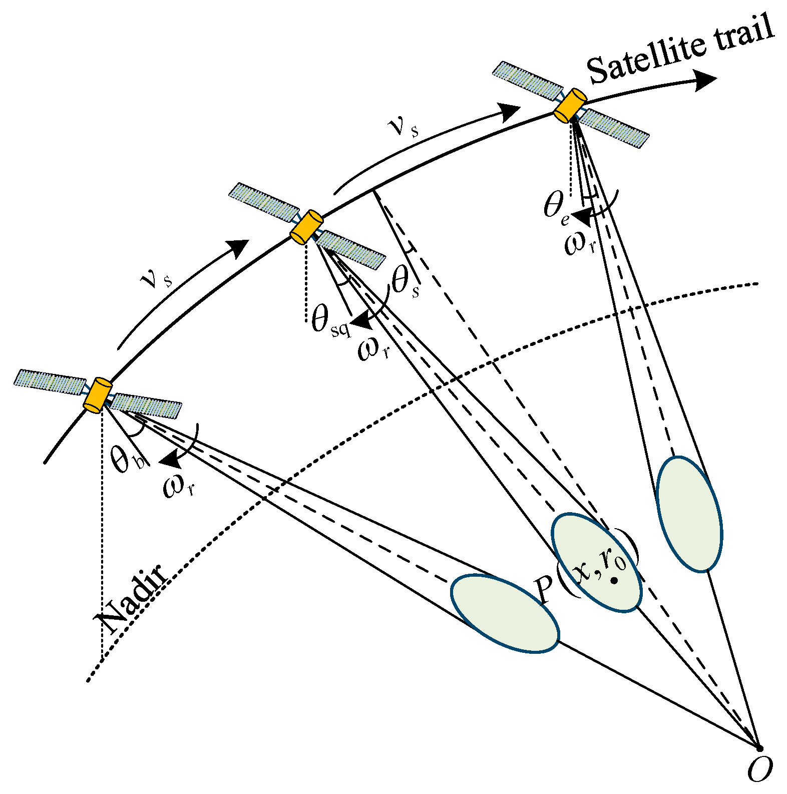
2. Design and Echo Signal Properties Analysis of the SBV-PRF Scheme

2.1. Design of the SBV-PRF Scheme

The design of an SBV-PRF varying scheme is presented in this section, the key to which is the addition of the judgment conditions of whether the scattered echo slides out of the echo receiving window [21] and whether it meets the sub-aperture division based on the variation repetition frequency. If the azimuth scanning angle of the squint sliding spotlight mode changes from large to small within the observation range, the specific design process of the SBV-PRF scheme is as shown in Figure 1.
Step 1: If the satellite platform velocity v s , the length of the azimuth antenna L a , the oversampling rate α s , and the central squint angle θ sq of the squint sliding spotlight SAR are known, then the initial pulse repetition frequency PRF ini can be calculated as:
PRF ini = α s 1.772 v s cos θ sq L a
To ensure that the PRF corresponding to each block of data designed meets the sampling rate requirements in the subsequent azimuth signal processing, α s is usually a value from 1.3 to 1.5;
Step 2: As the scanning angle decreases, the leading edge of the instantaneous echo gradually slides out of the receiving window and even aliases with the transmitting pulse. Therefore, it is necessary to determine the near-end slant range R ( γ n , θ a / 2 ; η ) of the instantaneous echo at any azimuth time η :
R ( γ n , θ a / 2 ; η ) = ( R e + H ) 2 + R e 2 2 R e ( H + R e ) cos ( α ( γ n , θ a / 2 ; η ) )
where
α ( γ n , θ a / 2 ; η ) = γ eq ( γ n , θ a / 2 ; η ) β ( γ n , θ a / 2 ; η )
β ( γ n , θ a / 2 ; η ) = arcsin ( sin ( γ eq ( γ n , θ a / 2 ; η ) ) R e + H H )
γ eq ( γ n , θ a / 2 ; η ) = arccos ( cos γ n cos ( θ sq + ω r η θ a / 2 ) )
where γ n is the near-end looking angle, θ a is the azimuth beam width, R e is the orbit radius, and H is the orbit height;
Step 3: According to Equation (2), the minimum value min ( R ( γ n , θ a / 2 ; η ) ) corresponding to the near-end slant range at all azimuth times is determined. Then the integer number of pulses n s experienced by the pulse from transmitting to receiving can be expressed as:
n s = 2 min ( R ( γ n , θ a / 2 ; η ) ) c PRF ini
where represents the floor operation and c represents the speed of light;
Step 4: The pulse repetition frequencies corresponding to all azimuth times are calculated to determine the value range of the pulse repetition frequency:
PRF min = n s 2 max ( R ( γ n , θ a / 2 ; η ) ) / c τ r τ p PRF max = n s 2 min ( R ( γ n , θ a / 2 ; η ) ) / c τ r τ p
where τ r represents the duration of the transmission pulse and τ p is the guard interval;
Step 5: As the instantaneous scanning angle decreases, the instantaneous echo gradually moves forward in the receiving window. If the transmitted pulse in the observation range satisfies the following conditions, PRF m remains unchanged:
n s < ( 2 R ( γ n , θ a / 2 ; η ) / c τ r τ p ) PRF m < ( n s + 1 )
where PRF m = 1 / PRI m ( m = 1 , 2 , 3 , , M ) represents the pulse repetition frequency corresponding to each block of data that meets the judgment criterion, M represents the total number of sub-blocks, and PRI m represents the corresponding pulse repetition interval.
If the above judgment criterion is not met, it means that the sequence corresponding to each data block with pulse repetition frequency PRF m has been generated, the number of sampling points N a , m satisfying Equation (8) can be obtained, and the central squint angle and beam scanning angle of each sub-block can be determined. At the same time, it is necessary to adjust PRF m to 1 / ( PRI m Δ PRI m ) and then make the following judgments:
n s < 2 R ( γ n , θ a / 2 ; η ) / c τ r τ p PRI m Δ PRI m < ( n s + 1 )
where Δ PRI m in the range of ( 0 , PRI max PRI min ) is the pulse repetition interval increment corresponding to each block of data;
Step 6: To reduce the azimuth acquisition time of each block of data designed enough to eliminate the additional Doppler aliasing bandwidth caused by the change in the Doppler center in the squint sliding spotlight mode, it is necessary to combine the sub-aperture division to make the judgment. If the azimuth acquisition time designed by the system satisfies the following conditions, the process returns to Equation (8). If the following conditions are not met, Δ PRI m needs to be adjusted and the process returns to Equation (9):
N a , m PRF m < ( PRF ini B f ) | k rot |
where B f is the azimuth beam bandwidth and k rot is the varying rate of the Doppler center of the instantaneous azimuth beam;
Step 7: According to the two judging criteria, the designed SBV-PRF sequence can be finally obtained.
The results according to the design flow of the SBV-PRF transmission scheme are illustrated in Figure 2. It can be seen that the operated values of the varying PRF technique continuously change with the squint angle, while the number of PRFs in the SBV-PRF transmission scheme is reduced. Figure 2b show that the number of azimuth sampling points of the adjacent sub-aperture data of the SBV-PRF transmission scheme is roughly equal, and under the condition that the azimuth acquisition time of each set of sub-aperture data is sufficiently short, the corresponding change in k rot is less than 10 Hz/s. Therefore, Doppler spectrum aliasing caused by the varying of the Doppler center is eliminated.

2.2. Properties of Echo Signal with SBV-PRF Scheme

The imaging geometry model of the SBV-PRF scheme applied to spaceborne squint sliding spotlight SAR is shown in Figure 3. The azimuth antenna beam traverses the data blocks corresponding to different PRFs during scanning from the start scanning angle θ b to the end scanning angle θ e . O is the virtual rotation point where the center of each azimuth beam points farther than the imaging swath. During data acquisition, the satellite platform velocity v s and the azimuth beam scanning rate ω r remain unchanged. θ sq is the central squint angle, θ s ( η block ) is the instantaneous squint angle corresponding to the target at time η block . η block is the time series generated by the SBV-PRF scheme. For any point target P ( x , r 0 ) , ignoring the amplitude weighting of the signal envelopes in the range and the azimuth, the echo signal received by the SBV-PRF sliding spotlight SAR in the squint scene is expressed as [22,23]:
s s block ( τ block , η block ) = exp { j π K r ( τ block 2 R ( η block ) c ) 2 } exp { j 4 π R ( η block ) λ }
where K r is the transmitted pulse modulation frequency, c is the speed of light, λ is the wavelength, and R ( η block ) is the instantaneous slant range corresponding to the SBV-PRF transmission scheme.
The timing diagram of the SBV-PRF is shown in Figure 4, where the SBV-PRF pulse transmission time η block is represented by a solid line arrow, the uniform pulse transmission time η uni arrow is represented by a dotted line arrow, and the interval between the two is Δ τ block . τ block is the range time relative to the SBV-PRF azimuth sampling time. However, in subsequent signal processing, it is necessary to convert τ block into the distance time τ corresponding to the uniform pulse emission time. Then the relationship between τ block and τ is τ block = τ + Δ τ block , where Δ τ blcok = η uni η blcok . In addition, it is the block change Δ τ block that changes the position of the transmission pulse interference, which can further improve the signal processing efficiency based on the effective acquisition of the echo data.
According to the SBV-PRF pulse transmission timing diagram in Figure 4, the echo signal expressed by Δ τ block is derived as:
s s block ( τ , η block ) = exp { j π K r ( τ + Δ τ block 2 R ( η block ) c ) 2 } exp { j 4 π R ( η block ) λ }
where
R ( η block ) = r 0 2 + v s 2 ( η block η c ) 2 2 r 0 v s ( η block η c ) sin θ sq
where η c = x / v g is the azimuth position of the point target and v g is the beam footprint velocity without considering the azimuth beam rotation.
The echo signal of sub-aperture m at the sampling frequency PRF m can be expressed as [24]:
s s m ( x , r 0 ; η block , m ) = rect { τ + Δ τ block , m R ( η block , m ) / c T r } rect { η block , m η c / A T d }             exp { j π K r ( τ + Δ τ block , m 2 R ( η block , m ) c ) 2 } exp ( j 4 π R ( η block , m ) λ )
where η block , m = η m + t m , η m = ( N a / 2 , , N a / 2 1 ) / PRF m is the azimuth time series of sub-aperture m , N a is the number of azimuth samples for each set of sub-aperture data, PRF m is the azimuth sampling frequency of the sub-aperture m, t m is the time delay of the sub-aperture m relative to the entire signal bandwidth, T r is the transmission pulse duration, A = v f / v g is the sliding factor, v f is the beam-illuminated area velocity when considering the azimuth beam scanning, T d = 0.886 λ r 0 / ( L a v g cos 2 θ sq A ) is the synthetic aperture time of the squint sliding spotlight SAR, L a is the azimuth antenna length, and Δ τ block , m is the change value of the uniform pulse transmission time relative to the m-th sub-aperture pulse transmission time.
According to the principle of the stationary phase (POSP), the range Fourier transform is performed on Equation (14) and is expressed in the range-frequency domain as:
S s m ( f τ , η block , m ) = rect ( f τ B r ) rect ( η block , m η c / A T d ) exp ( j π f τ 2 K r )            exp ( j 4 π ( f c + f τ ) R ( η block , m ) c ) exp { 2 π f τ Δ τ block , m }
where B r is the bandwidth of the transmitted signal and f τ is the range frequency. To analyze the azimuth spectrum characteristics of each set of sub-aperture data, the instantaneous azimuth Doppler frequency corresponding to the sub-aperture m is expressed as:
f η , m ( f τ , η block , m ) = ( f c + f τ ) c ( R ( η block , m ) ) η m = 2 v s ( f c + f τ ) sin ( θ s , m ( η block , m ) ) c
where θ s , m ( η block , m ) = θ sq , m + ω r η block , m + Δ θ is the instantaneous squint angle of the m-th sub-aperture, θ sq , m is the central squint angle of the sub-aperture m, Δ θ [ θ a / 2 , θ a / 2 ] is the illumination range of the antenna beam, and θ a = 0.886 λ / L a = 0.886 c / ( f c L a ) , f c is the center carrier frequency. According to Equation (16), the total azimuth bandwidth of sub-aperture m is calculated as:
B tot , m = max { f η , m } min { f η , m }     = 2 v s cos θ sq , m λ θ a + | k rot , m | T sub , m + 2 v s B r sin θ sq , m c     B f , m + B sq , m
where T sub , m is the data acquisition length corresponding to sub-aperture m. The total azimuth Doppler bandwidth of the m-th sub-aperture includes two parts: the azimuth beam bandwidth B f , m and the additional bandwidth caused by the squint angle B sq , m .
The simulation of the influence of the squint additional bandwidth on the system bandwidth are shown in Figure 5. When the azimuth beam bandwidth is greater than 100 MHz, the total Doppler bandwidth is obviously extended, and the system has the problem of under-sampling. When the azimuth beam bandwidth is 100 MHz, the total Doppler bandwidth is still greater than the PRF of the intermediate sub-aperture echo data. It can be seen from Figure 5b that the ratio of the squint additional bandwidth to the beam bandwidth increases with the transmission bandwidth for different central squint angles and even exceeds the azimuth beam bandwidth. For the three-block data designed, the number of azimuth samples of each set of sub-aperture data and the scanning range of the azimuth beam are equal and the difference in the central squint angles between adjacent sub-apertures is small. Therefore, through analysis, it can be concluded that each sub-aperture has a Doppler spectrum aliasing phenomenon caused by squint angle.

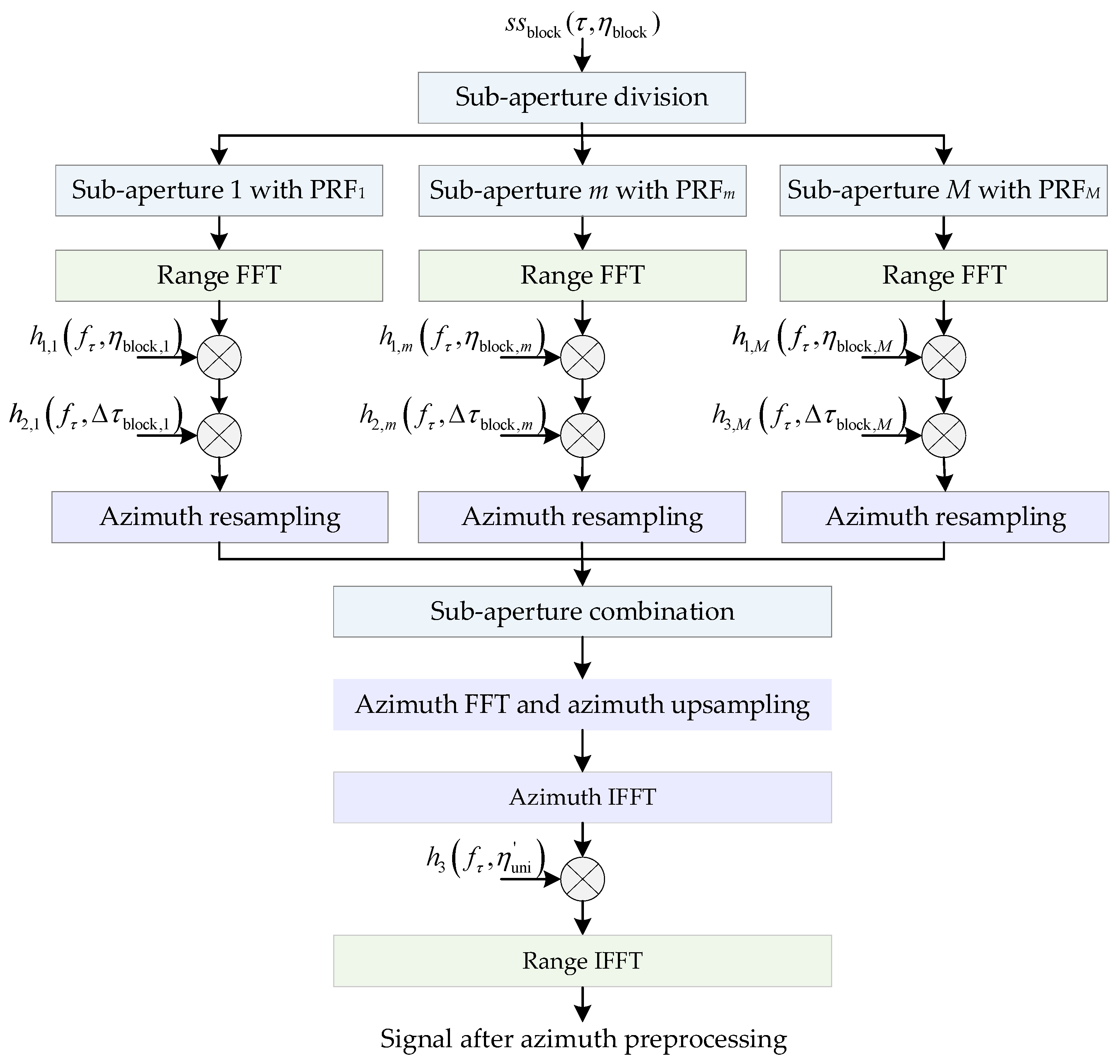
3. Signal Processing

According to the SBV-PRF echo signal properties, the sub-aperture division method, which is an effective method to solve the Doppler spectrum aliasing of squint sliding spotlight SAR mode, is proposed and applied to process the echo signal of squint sliding spotlight SAR mode generated SBV-PRF sampling method. The flowchart of the proposed signal processing method is shown in Figure 6. In this method, firstly, the sub-aperture division is performed according to the number of sub-block designed by SBV-PRF scheme, and then a de-skewing operation is performed on each set of sub-aperture echo data to eliminate the additional bandwidth caused by squint angles. Then, the azimuth resampling is performed on each set of sub-aperture data, azimuth signals with the uniform sampling are output. Furthermore, sub-aperture splicing and two-dimensional frequency domain up-sampling operations are performed. Finally, the original Doppler history of the squint sliding spotlight SAR data is restored through range frequency domain re-skewing processing [25].
Firstly, the sub-aperture data are divided according to the number of sub-blocks designed by the SBV-PRF scheme. The expression of the echo data for the sub-aperture m is shown in Equation (12). According to the simulation results in Figure 5, the range–azimuth coupling bandwidth caused by the squint angle is relatively large. It is necessary to perform de-skewing in the range frequency domain to eliminate the problem of the Doppler spectrum aliasing. The de-skewing function for the sub-aperture m is as follows:
h 1 , m ( f τ , η block , m ) = exp ( j 4 π v s ( f c + f τ ) sin ( θ sq , m ) η block , m c )
Before the azimuth resampling of each set of sub-aperture data, the part of the change in the SBV-PRF system relative to the uniform pulse sequence need to be compensated in the range frequency domain. The range filter for recovering the range migration is:
h 3 , m ( f τ , Δ τ block , m ) = exp ( j 2 π f τ Δ τ block , m )
After range frequency domain de-skewing and range migration correction, the echo signal Ss m ( f τ , η block , m ) of the m-th sub-aperture is expressed as:
Ss m ( f τ , η block , m ) A W r ( f τ ) w a ( η block , m ) exp [ j 4 π ( f τ + f c ) R ( η block , m ) c ]           exp [ j π f τ 2 K r ] exp [ j 4 π v s sin θ sq , m ( f τ + f c ) c η block , m ]
where A is a complex constant, W r ( ) is the envelope at range frequency f τ , and w a ( ) is the envelope of azimuth time η block , m for sub-aperture m.
According to Equation (20), after the range migration correction, the azimuth data corresponding to each sub-aperture have the problem of block varying non-uniform sampling, so azimuth resampling for each set of sub-aperture data must be performed. After each set of sub-aperture data is interpolated into the azimuth uniform sampling frequency through up-sampling and down-sampling operations, the sub-aperture combination process is performed. To restore the non-aliased Doppler spectrum, it is necessary to implement the up-sampling process with zero padding along the azimuth in the two-dimensional frequency domain. The amount of zero padding is computed as:
Δ N a = ( f s B tol PRF uni ) T
where α s is the oversampling factor, B tol is the total Doppler bandwidth corresponding to the central squint angle θ sq , PRF uni is the uniform sampling frequency obtained after azimuth resampling, T = n a / PRF uni is the azimuth acquisition data time after sub-aperture combination, and n a is the total number of azimuth samples after sub-aperture combination.
As the de-skewing process of the signal in the azimuth time domain-range frequency domain introduces an additional phase term, the redundant phase term must be compensated after all the sub-aperture data combinations to restore the original Doppler history of the signal at the uniform azimuth sampling frequency.
The up-sampled signal is inversely Fourier-transformed and the result is multiplied by the re-skewing function in the azimuth time domain-range frequency domain to obtain the echo signal that removes the de-skewing and introduces additional phase item. The re-skewing function is expressed as follows:
h 4 ( f τ , η uni ) = exp ( j 4 π v s f τ η uni sin θ sq c )
where η uni = i Δ η uni , i = P / 2 , , P / 2 1 , Δ η uni = 1 / PRF uni , P and PRF uni are the number of azimuth samples and the azimuth sampling frequency, respectively, after azimuth up-sampling.
Finally, the azimuth inverse Fourier transform of the signal after re-skewing in the azimuth time domain-range frequency domain is performed to obtain the complete original data.

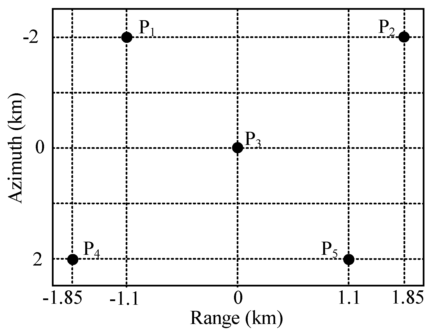
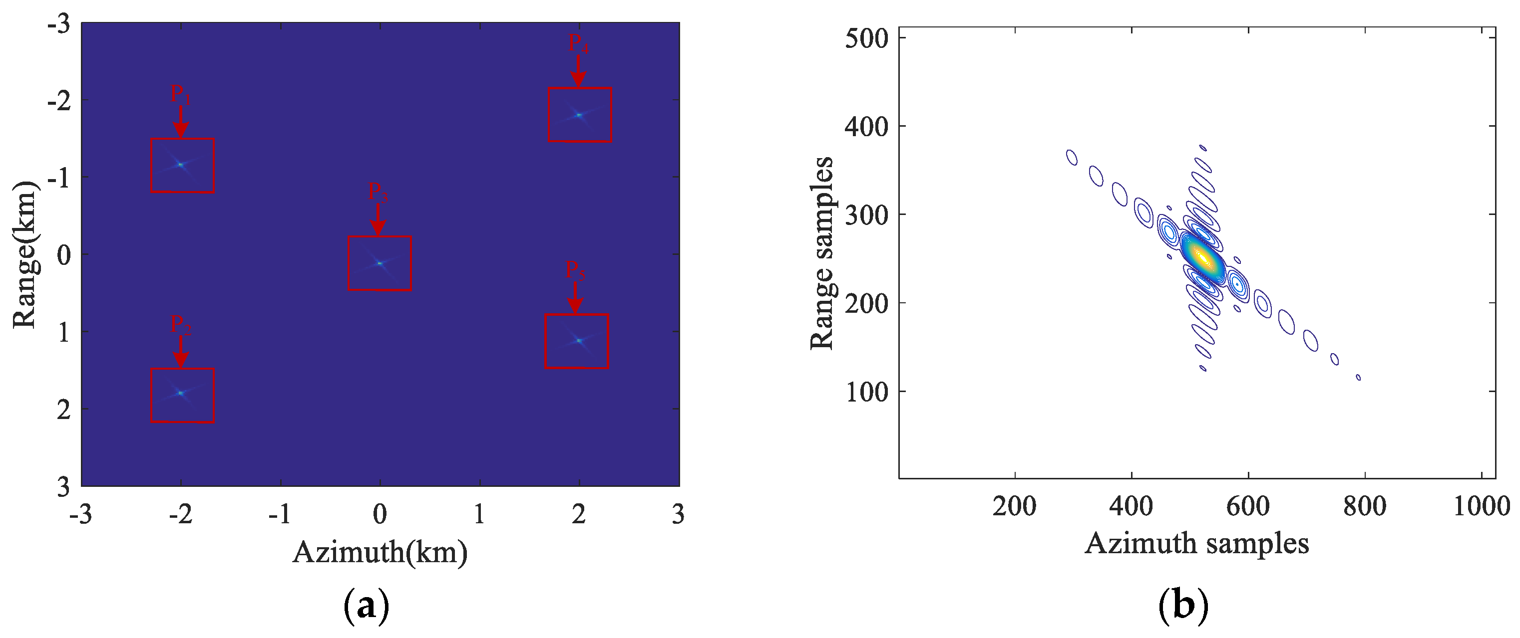
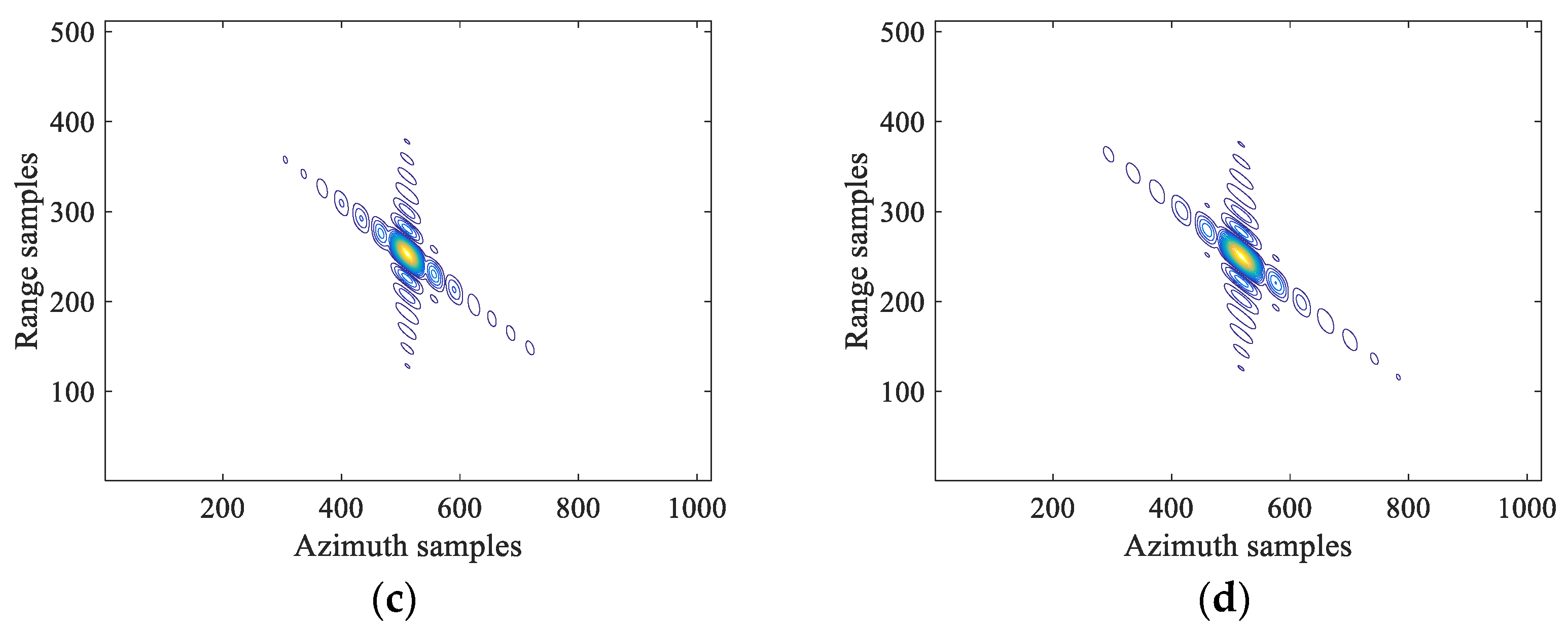
4. Simulation Results

To verify the effectiveness of the azimuth signal processing method of the proposed SBV-PRF squint sliding spotlight mode, the simulation experiment of a point target is executed in this section. The simulation parameters are shown in Table 1. Firstly, an imaging scene containing five-point targets is set up, as shown in Figure 7.
The interval between the pulse transmission time of the SBV-PRF scheme and the uniform pulse transmission time is changed in blocks. The real part simulation of the echo signal acquired with the SBV-PRF applied to the squint sliding spotlight SAR is shown in Figure 8a. From the figure, it can be clearly seen that the SBV-PRF scheme avoids the problems of receiving blind area of the F-PRF scheme and serious azimuth non-uniform sampling of the varying repetition frequency. The sub-aperture is divided according to the designed number of sub-blocks. The real parts of the echo signal and the two-dimensional spectrum of the middle sub-aperture data are shown in Figure 8b. It can be seen that the Doppler spectrum aliasing phenomenon still exists in the two-dimensional spectrum. The azimuth absolute Doppler bandwidth of each sub-aperture is restricted within the azimuth sampling frequency by performing a de-skewing operation in the range frequency domain. Then, the range migration recovery compensation and azimuth resampling are performed to interpolate the block varying non-uniform sampling signal into the uniform azimuth sampling signal. Furthermore, the sub-aperture combination processing is carried out. The reconstructed two-dimensional spectrum is shown in Figure 8c. Finally, up-sampling and range frequency-dependent re-skewing are performed, and the non-aliased two-dimensional spectrum of the original data is obtained, as shown in Figure 8d.
To further illustrate the effectiveness of the proposed signal process method, Figure 9 shows the lattice imaging results and the contour of the point targets P1, P3, and P5. The three-point targets are well focused. The performance parameters such as the resolution, peak sidelobe ratio (PSLR), and integral sidelobe ratio (ISLR) of the proposed method are listed in Table 2. PSRL represents the ratio of the height of the largest side-lobe to the height of the main lobe, and ISLR represents ratio between the energy of side-lobe to the energy of main lobe. From the data in the Table 2, it can be seen that the proposed signal processing method of squint sliding spotlight SAR combined with the SBV-PRF and sub-aperture division in this paper is effective.

5. Conclusions

The spaceborne squint sliding spotlight SAR system is capable of capturing multi-angle high-resolution ultra-wide SAR images, presenting important practical application prospects in future wide-area searches and large-scale surveillance. Firstly, the SBV-PRF scheme proposed in this paper helps improve the processing efficiency of subsequent azimuth signal resampling. Based on the characteristics of the SBV-PRF and the characteristics of the squint sliding spotlight echo data, the Doppler aliasing problem caused by the squint angle is eliminated through range frequency domain–azimuth time domain de-skewing. Then the range migration is compensated for in the range frequency domain and the two-dimensional spectrum with uniform sampling frequency is successfully reconstructed after resampling, which solves the problem of SBV-PRF azimuth block varying non-uniform sampling. Finally, the non-aliased Doppler history of the target is recovered through azimuth up-sampling and re-skewing. Compared with the continuously varying repetition frequency technology, the sub-aperture varying repetition frequency technology greatly reduces the difficulty of azimuth signal pre-processing while ensuring the complete acquisition of the complete echo data of the squint sliding spotlight mode.

Author Contributions

Conceptualization, W.X.; methodology, W.X.; software, W.X. and Z.Z.; validation, W.X. and P.H.; formal analysis, Z.Z.; investigation, W.X. and Z.Z.; resources, W.X. and W.T.; data curation, Z.Z.; writing—original draft preparation, W.X. and Z.Z.; writing—review and editing, W.X. and P.H.; visualization, P.H.; supervision, W.T and Y.Q.; project administration, P.H. and W.T.; funding acquisition, W.X. and P.H. All authors have read and agreed to the published version of the manuscript.

Funding

This research was supported by National Natural Science Foundation of China under grant numbers 62071258 and 61971246, in part by Natural Science Foundation of Inner Mongolia Autonomous Region, grant numbers 2020ZD18 and 2021MS06004, and in part by Science and Technology Planning Project of Inner Mongolia Autonomous Region under grant number 2020GG0073.

Institutional Review Board Statement

Not applicable.

Informed Consent Statement

Not applicable.

Data Availability Statement

No applicable.

Conflicts of Interest

The authors declare no conflict of interest.

References

  1. Xu, W.; Hu, J.; Huang, P.; Tan, W.; Dong, Y. Processing of Multichannel Sliding Spotlight SAR Data with Large Pulse Bandwidth and Azimuth Steering Angle. IEEE Trans. Geosci. Remote Sens. 2021, 60, 5202414. [Google Scholar] [CrossRef]
  2. He, F.; Dong, Z.; Zhang, Y.; Jin, G.; Yu, A. Processing of Spaceborne Squinted Sliding Spotlight and HRWS TOPS Mode Data Using 2-D Baseband Azimuth Scaling. IEEE Trans. Geosci. Remote Sens. 2020, 58, 938–955. [Google Scholar] [CrossRef]
  3. Zhao, S.; Deng, Y.-K. Attitude-Steering Strategy for Squint Spaceborne Synthetic Aperture Radar. IEEE Geosci. Remote Sens. Lett. 2016, 13, 1163–1167. [Google Scholar] [CrossRef]
  4. Villano, M.; Krieger, G.; Moreira, A. Staggered SAR: High-Resolution Wide-Swath Imaging by Continuous PRI Variation. IEEE Trans. Geosci. Remote Sens. 2014, 52, 4462–4479. [Google Scholar] [CrossRef]
  5. Yin, W.; Ding, Z.; Yang, S.; Li, Y.; Zeng, T.; Long, T. A Continuous PRI Variation Method for Geosynchronous SAR with Elliptical Orbit. In Proceedings of the 2015 IEEE International Geoscience and Remote Sensing Symposium (IGARSS), Milan, Italy, 26–31 July 2015; pp. 4582–4585. [Google Scholar]
  6. Villano, M.; Peixoto, M.N.; Ustalli, N.; Mittermayer, J.; Krieger, G.; Moreira, A. Decorrelating Ambiguities in SAR Interferometry Through Slight PRI Variation. IEEE Trans. Geosci. Remote Sens. 2022, 60, 5240413. [Google Scholar] [CrossRef]
  7. Peixoto, M.N.; Villano, M. Processing Techniques for Nadir Echo Suppression in Staggered Synthetic Aperture Radar. IEEE Geosci. Remote Sens. Lett. 2022, 19, 4505705. [Google Scholar] [CrossRef]
  8. Martone, M.; Gollin, N.; Villano, M.; Rizzoli, P.; Krieger, G. Predictive Quantization for Data Volume Reduction in Staggered SAR Systems. IEEE Trans. Geosci. Remote Sens. 2020, 58, 5575–5587. [Google Scholar] [CrossRef] [Green Version]
  9. Villano, M.; Krieger, G.; Moreira, A. Staggered-SAR for High-Resolution Wide-Swath Imaging. In Proceedings of the IET International Conference on Radar Systems (Radar 2012), Glasgow, UK, 22–25 October 2012; pp. 1–6. [Google Scholar]
  10. Zhang, Y.; Yu, Z.; Li, C. Effects of PRF Variation on Spaceborne SAR Imaging. In Proceedings of the 2013 IEEE International Geoscience and Remote Sensing Symposium-IGARSS, Melbourne, VIC, Australia, 21–26 July 2013; pp. 1336–1339. [Google Scholar]
  11. Zeng, H.-C.; Chen, J.; Liu, W.; Yang, W. Modified Omega-k Algorithm for High-Speed Platform Highly-Squint Staggered SAR Based on Azimuth Non-Uniform Interpolation. Sensors 2015, 15, 3750–3765. [Google Scholar] [CrossRef] [PubMed] [Green Version]
  12. Chen, S.; Qiu, X.; Shang, M.; Han, B. An Improved Imaging Algorithm for High-Resolution Spotlight SAR with Continuous PRI Variation Based on Modified Sinc Interpolation. Sensors 2019, 19, 389. [Google Scholar] [CrossRef] [PubMed] [Green Version]
  13. Hu, L.; Wang, G.; Hou, L. Spatial-Variant SAR Range Cell Migration Correction Using Subaperture Strategy. Sensors 2021, 21, 2444. [Google Scholar] [CrossRef] [PubMed]
  14. Li, N.; Bie, B.; Bao, Z. A High-Squint TOPS SAR Imaging Algorithm for Maneuvering Platforms Based on Joint Time-Doppler Deramp Without Subaperture. IEEE Geosci. Remote Sens. Lett. 2019, 17, 1899–1903. [Google Scholar] [CrossRef]
  15. Men, Z.; Wang, P.; Li, C.; Chen, J.; Liu, W.; Fang, Y. High-Temporal-Resolution High-Spatial-Resolution Spaceborne SAR Based on Continuously Varying PRF. Sensors 2017, 17, 1700. [Google Scholar] [CrossRef] [PubMed] [Green Version]
  16. Guo, Y.; Cui, L.; Wang, P.; Chen, J. A Modified Imaging Algorithm for Space-Borne Sliding Spotlight SAR Based on Azimuth Non-Uniform Sampling. In Proceedings of the IGARSS 2022—2022 IEEE International Geoscience and Remote Sensing Symposium, Kuala Lumpur, Malaysia, 17–22 July 2022; pp. 1820–1823. [Google Scholar]
  17. Song, L.; Bai, B.; Li, X.; Niu, G.; Liu, Y.; Zhao, L.; Zhou, H. Analysis of Hypersonic Platform-Borne SAR Imaging: A Physical Perspective. Remote Sens. 2021, 13, 4943. [Google Scholar] [CrossRef]
  18. Wu, Y.; Zhang, Y.; Guang-Cai, S.; Bao, Z. Azimuth Resampling Processing for Highly Squinted Synthetic Aperture Radar Imaging With Several Modes. Geosci. Remote Sens. IEEE Trans. 2014, 52, 4339–4352. [Google Scholar] [CrossRef]
  19. Xu, W.; Li, R.; Fang, C.; Huang, P.; Tan, W.; Qi, Y. Azimuth Multichannel Reconstruction Based on Advanced Hyperbolic Range Equation. Remote Sens. 2021, 13, 4705. [Google Scholar] [CrossRef]
  20. Korkmaz, F.; Antoniou, M. A New Concept of Contiguous-Swath SAR Imaging with High Resolution: Strip-Spot SAR. Sensors 2022, 22, 9153. [Google Scholar] [CrossRef] [PubMed]
  21. Zhang, Z.; Xu, W.; Huang, P.; Tan, W.; Gao, Z.; Qi, Y. Azimuth Full-Aperture Processing of Spaceborne Squint SAR Data with Block Varying PRF. Sensors 2022, 22, 9328. [Google Scholar] [CrossRef] [PubMed]
  22. Wu, Y.; Xing, M.; Sun, G.; Deng, J.; Bao, Z. An Azimuth Resampling based Imaging Algorithm for Highly Squinted Sliding Spotlight and TOPS SAR. In Proceedings of the EUSAR 2014; 10th European Conference on Synthetic Aperture Radar, Berlin, Germany, 3–5 June 2014; pp. 1–4. [Google Scholar]
  23. Hu, X.; Wang, P.; Zeng, H.; Guo, Y. An Improved Equivalent Squint Range Model and Imaging Approach for Sliding Spotlight SAR Based on Highly Elliptical Orbit. Remote Sens. 2021, 13, 4883. [Google Scholar] [CrossRef]
  24. Ding, Z.; Zheng, P.; Li, H.; Zhang, T.; Li, Z. Spaceborne High-Squint High-Resolution SAR Imaging Based on Two-Dimensional Spatial-Variant Range Cell Migration Correction. IEEE Trans. Geosci. Remote Sens. 2022, 60, 5240114. [Google Scholar] [CrossRef]
  25. Chen, J.; Kuang, H.; Yang, W.; Liu, W.; Wang, P.B. A Novel Imaging Algorithm for Focusing High-Resolution Spaceborne SAR Data in Squinted Sliding-Spotlight Mode. IEEE Geosci. Remote Sens. Lett. 2016, 13, 1577–1581. [Google Scholar] [CrossRef] [Green Version]
Figure 1. Flowchart of the design of the SBV-PRF sequence.
Electronics 12 02835 g001
Figure 2. Design results of SBV-PRF scheme and varying PRF technique. (a) The change in varying PRF technique with squint angle; (b) the change in SBV-PRF with squint angle; (c) the change in k rot with scanning angle.
Electronics 12 02835 g002
Figure 3. Imaging geometry of squinted sliding spotlight SAR with SBV-PRF.
Electronics 12 02835 g003
Figure 4. Schematic diagram of the SBV-PRF transmitting sequence.
Electronics 12 02835 g004
Figure 5. The ratio of squint additional bandwidth to beam bandwidth of middle sub-aperture data. (a) The change in ratio Φ with instantaneous squint angle; (b) the change in ratio Φ with transmitted bandwidth.
Electronics 12 02835 g005
Figure 6. Flowchart of the proposed azimuth pre-processing method.
Electronics 12 02835 g006
Figure 7. The designed imaged scene with five-point targets.
Electronics 12 02835 g007
Figure 8. Azimuth pre-processing results of squint sliding spotlight SAR data with SBV-PRF. (a) Real part of echo of the whole scene; (b) echo data of the middle sub-aperture data; (c) the 2D spectrum after sub-aperture combination; (d) the 2D spectrum after azimuth pre-processing.
Electronics 12 02835 g008
Figure 9. Contour plots of three imaged point targets. (a) Imaging results of five-point targets; (b) contour of P1; (c) contour of P3; (d) contour of P5.
Electronics 12 02835 g009aElectronics 12 02835 g009b
Table 1. Simulation parameters.
ParameterValue
Relative platform velocity7200 m/s
Slant range of the scene center700 km
Carrier frequency5.6 GHz
Azimuth antenna length6 m
Number of PRFs3
Azimuth beam rotation rate2.68°/s
Middle squint angle25°
System PRF2721/2762/2801 Hz
Pulse bandwidth100 MHz
Range sampling frequency120 MHz
Pulse duration 6   μ s
Table 2. Performance indicators to measure imaging quality five-point targets.
TargetAzimuthRange
Res.(m)PSLR(dB)ISLR(dB)Res.(m)PSLR(dB)ISLR(dB)
P11.328−13.27−10.053.558−12.97−9.94
P31.328−13.25−10.033.578−12.98−9.95
P51.328−13.27−10.043.571−12.96−9.93
Disclaimer/Publisher’s Note: The statements, opinions and data contained in all publications are solely those of the individual author(s) and contributor(s) and not of MDPI and/or the editor(s). MDPI and/or the editor(s) disclaim responsibility for any injury to people or property resulting from any ideas, methods, instructions or products referred to in the content.

