Article

Dynamic Reconfiguration Method of Photovoltaic Array Based on Improved HPSO Combined with Coefficient of Variation

College of Electronics and Information Engineering, Shanghai University of Electric Power, Shanghai 201306, China
*
Author to whom correspondence should be addressed.
Electronics 2023, 12(12), 2744; https://doi.org/10.3390/electronics12122744
Submission received: 30 May 2023 / Revised: 13 June 2023 / Accepted: 18 June 2023 / Published: 20 June 2023
(This article belongs to the Topic Energy Saving and Energy Efficiency Technologies)

Abstract

:
In order to address the issue of power loss resulting from partial shadow and enhance the efficiency of photovoltaic power generation, the photovoltaic array reconfiguration technology is being increasingly utilized in photovoltaic power generation systems. This paper proposes a reconfiguration method based on improved hybrid particle swarm optimization (HPSO) for the photovoltaic array of TCT (total-cross-tied) structure. The motivation behind this method is to get the best reconfiguration scheme in a simple and efficient manner. The ultimate goal is to enhance the output power of the array, save energy, and improve its overall efficiency. The improved HPSO introduces the concept of hybridization in genetic algorithms and adopts a nonlinear decreasing weight method to balance the local search and global search ability of the algorithm and prevent it from falling into the local optimal solution. The objective function used is the variation coefficient of the row current without the weight factor. This approach saves time and balances the row current of the array by altering the electrical connection of the component. In the 4 × 3 array, the improved HPSO is compared with the Zig-Zag method. In the 9 × 9 array, the improved HPSO is compared with the CS (competence square) method and the improved SuDoKu method. The simulation results show that the power enhancement percentage of the improved HPSO is between 6.39% and 28.26%, and the power curve tends to single peak characteristics. The improved HPSO has a smaller mismatch loss and a higher fill factor in the five shadow modes, which can effectively improve the output power, and it is convenient to track the maximum power point later.

1. Introduction

With the growing concern for environmental preservation and the rising demand for energy, traditional fossil energy is gradually exhausted, and people pay more and more attention to renewable energy. As one of the cleanest and most promising power generation methods, solar energy has penetrated many engineering applications [1,2,3]. The advantages of solar power generation are noise-free operation, low maintenance, and zero carbon emissions [4,5,6]. However, in practice, photovoltaic arrays are susceptible to local shadow (PSC) problems caused by building shadows, trees, dust, clouds, and bird droppings. The output current of the partially shaded photovoltaic module does not meet the required standards, leading to voltage inversion and hot spot phenomena, which can affect the power supply to the load. To prevent damage to the photovoltaic modules from overheating, bypass diodes are commonly connected in parallel at both ends, but this will make the P-V curve of the photovoltaic array have multi-peak characteristics, which is not ideal for maximum power point tracking (MPPT) [7].
The power loss of photovoltaic arrays is also related to their interconnection structure. Common structures include series-parallel (SP), bridge (BL), honeycomb (HC), bridge-honeycomb (BL-HC), and total-cross-tied (TCT), among which total-cross-tied (TCT) has excellent performance [8].
In order to solve the problems caused by local shadows and improve the output power, the maximum power point technology is used to deal with the multi-power peak problem. Many soft computing techniques [9,10,11] and fractional-order controllers [12,13] are used in single-machine and grid-connected systems to enhance manpower. However, these techniques attempt to achieve global peaks rather than solve multiple power peak problems. In order to overcome the multi-peak characteristics in the P-V curve, the researchers envisaged a new solution, which is to rearrange the photovoltaic panels in the photovoltaic array through array reconfiguration technology. The reconfiguration of photovoltaic panels in the array can be achieved by physical repositioning or electrical array reconfiguration (EAR).
In the TCT structure, References [14,15,16] proposed the widely used “irradiance equalization” idea. The purpose of irradiance balance is to make the irradiance between the series rows as similar as possible [17]. In other words, its basic idea is to minimize the difference between the row currents so that they do not limit the current of the entire PV array. By rearranging the photovoltaic modules, the irradiance balance between rows is realized [18,19]. Therefore, a uniform shadow dispersion is achieved to increase the output power of the PV array under partial shading conditions.
Photovoltaic array reconfiguration includes static reconfiguration and dynamic reconfiguration. Static reconfiguration refers to the change in the physical location of the photovoltaic modules, and the array can disperse local shadows.
In [20], the SuDoKu puzzle mode was used to physically arrange the modules in the TCT-connected photovoltaic array. Without modifying the TCT connection, the random SuDoKu configuration was used to change the physical position of the PV plate, and the shading effect was distributed on the array, thereby enhancing the power generation capacity. The authors of [21] analyzed the enhanced performance of the array PV array under cloudy conditions, and the SuDoKu scheme showed better performance under other array configurations under moving shadow conditions. In [22], the usual Sudoku scheme is optimized by new rules to reduce the impact of mutual shading. However, for non-square PV arrays, the SuDoKu mode is not applicable. In [23], the authors proposed a static shade-tolerant configuration to improve the efficiency under shaded conditions by reducing the loss caused by mismatches. This work proposed a simplified algorithm to determine the position of each panel in the array. The authors of [24,25] used magic square (MS), which is a logic-based digital placement puzzle, to increase maximum power. This magic square configuration can also be applied to other large-scale photovoltaic arrays and has higher performance than the traditional TCT configuration. The authors of [26] proposed and tested a new puzzle-based reconfiguration scheme called the Dominant Square Puzzle (DS). The effectiveness of different configurations is compared, and the results show the potential of the dominant square method. The authors of [27] proposed a static shade decentralized physical array relocation (SD-PAR) technology for photovoltaic arrays to enhance the power generation of photovoltaic arrays when partially shaded. SD-PAR reduces power loss by distributing shading effects throughout the photovoltaic array. The authors of [28] proposed a physical array reconfiguration technique based on the Lo Shu concept for shadow dispersion.
Reference [29] proposed a new Zig-Zag technology to reduce losses and increase power generation. In [30], the CS competence square technique is proposed for the physical rearrangement of arrays, which can effectively disperse local shadows and has outstanding advantages in performance. In [31], an improved SuDoKu technique was proposed, and the performance of the proposed mode and the existing SuDoKu mode under different shadow conditions was studied. However, this method can only be applied to square matrices. Static reconfiguration improves the output power according to the preset interconnection method and cannot dynamically change the position of the module, so it is not suitable for large photovoltaic arrays [32].
In the dynamic reconfiguration technology, the physical position of the component remains unchanged, and the irradiance balance is achieved by dynamically changing the electrical connection of the photovoltaic module.
The authors of [33] proposed a fully reconfigurable dynamic electrical scheme (DES) for photovoltaic generators. The author introduced two different TCT structure reconfiguration control algorithms and used the principle of irradiance equalization: random search and deterministic algorithm. The authors of [34] proposed an iterative hierarchical sorting algorithm based on the irradiance equalization method to achieve near-optimal configuration in a small number of iterations. In [35], the author used a modeling technique that can generate spatially dispersed irradiance profiles incident on the surface of photovoltaic modules at the application site. The goal of the algorithm is to provide near-optimal array reconfiguration in terms of irradiance equalization and the number of switching actions. In the adaptive array reconfiguration strategy, the authors of [36] divide the panel into two parts—the fixed part and the adaptive part. Once the shadow is detected, the switching matrix reconfigures the PV module, and the module in the adaptive part compensates for the shadow module in the fixed part. Therefore, the photovoltaic system can produce constant power even in the case of shading. The switching matrix is controlled by an evolutionary control algorithm or intelligent control algorithm. Reference [37] developed a scanning algorithm that scans the array and determines how to attach the adaptive part to the fixed part to maximize efficiency. The authors of [38] proposed an adaptive reconfiguration method based on fuzzy control. Fuzzy control based on the shading degree of the photovoltaic array can quickly respond to changes in the external environment. In References [39,40], an artificial method for PV array reconfiguration based on the fuzzy partition is proposed. For the fixed panel structure, a TCT connection is adopted. The algorithm takes the radiation value and current value of the adaptive panel and the fixed panel as input parameters. After processing the fuzzy calculation, the detection value is transmitted to the control and decision-making unit. The results obtained from this unit are sent to the switching matrix circuit. The most important advantage of the reconfiguration method based on the fuzzy partition is that it can provide fast solutions for large-scale photovoltaic systems. The authors of [41] proposed a photovoltaic system reconfiguration strategy to reduce the shading effect by introducing intelligent control logic. This technology is highly recommended for constant power loads because the output current remains constant, and the changing atmospheric conditions are not considered.
In summary, early attempts to solve the problem of partial shading of photovoltaic arrays involved (1) skilled labor, (2) complex rewiring, and (3) electrical switch layouts. While arranging electrical switches proved effective, finding an optimal combination was a challenging and time-consuming task. As a result, optimization techniques are a viable alternative to effectively address these challenges.
In recent years, heuristic algorithms have been gradually applied to array reconfiguration, including genetic algorithm (GA) [42], particle swarm optimization (PSO) [43], grasshopper algorithm (GOA) [44], bald eagle search algorithm (BES) [45], improved mayfly algorithm (IMA) [46], coyote optimization algorithm (COA) [47], Harris hawks optimizer (HHO) [48] etc. Although these algorithms have achieved good performance, there are still some limitations: (1) These algorithms contain huge calculation steps and have many parameters. (2) They show inconsistent behavior in the system response. (3) The convergence speed is slow. (4) The optimal response of the system depends on the additional adjustable parameters. For example, the weight factors used in the objective functions of GA, PSO, and GOA are determined by a trial and error method, which takes a lot of time, and the selection of weight factors in the objective function will affect the performance of the algorithm [49].
In order to solve the problems of existing algorithms and find simpler and faster algorithms, and maximize the global maximum power (GMP) extracted from the shadowed array, an optimal reconfiguration method of photovoltaic array based on improved hybrid particle swarm optimization (HPSO) is proposed. The main contributions of this paper are as follows:
  • By introducing the concept of hybridization in genetic algorithms, the nonlinear decreasing weight method is used to balance the local search and global search ability of the algorithm to prevent it from falling into the local optimal solution. A new HPSO-based PV array reconfiguration scheme is proposed to maximize the GMP extracted from the PV system.
  • The variation coefficient of the row current is used as the objective function, and there is no need to try and error the weight factor of the objective function, which saves a lot of time.
  • In five standard shading modes of 4 × 3 non-square matrix and 9 × 9 square matrix, the proposed HPSO provides performance verification and superiority confirmation that is superior to the existing solutions.
The reconfiguration performance of improved HPSO is studied by three evaluation indexes of mismatch loss, fill factor, and power enhancement percentage and compared with Zig-Zag, CS, improved SuDoKu, and other methods.
The remainder of the paper is organized as follows: Section 2 provides a detailed introduction to the characteristics of TCT structure, modules, and arrays. In Section 3, an array reconfiguration method based on improved HPSO combined with the coefficient of variation is described. Section 4 focuses on experimental evaluation; the numerical results, analysis, and discussion are introduced in detail. Finally, the main findings are summarized and concluded in Section 5.

2. System Description

In general, the power generation of a single photovoltaic module does not meet the greater power demand, so it is necessary to connect the photovoltaic modules in series and parallel to form a photovoltaic array. One of the main reasons for reducing the power generation of photovoltaic arrays is partial shading (PS). Due to the bypass of the panel, the occurrence of shadows in the panel is attributed to multiple peaks. The reconfiguration in the photovoltaic array allows the panels in the photovoltaic array to be rearranged, resulting in uniform shadow dispersion. This method is an effective method for achieving uniform row current under shade dispersion.

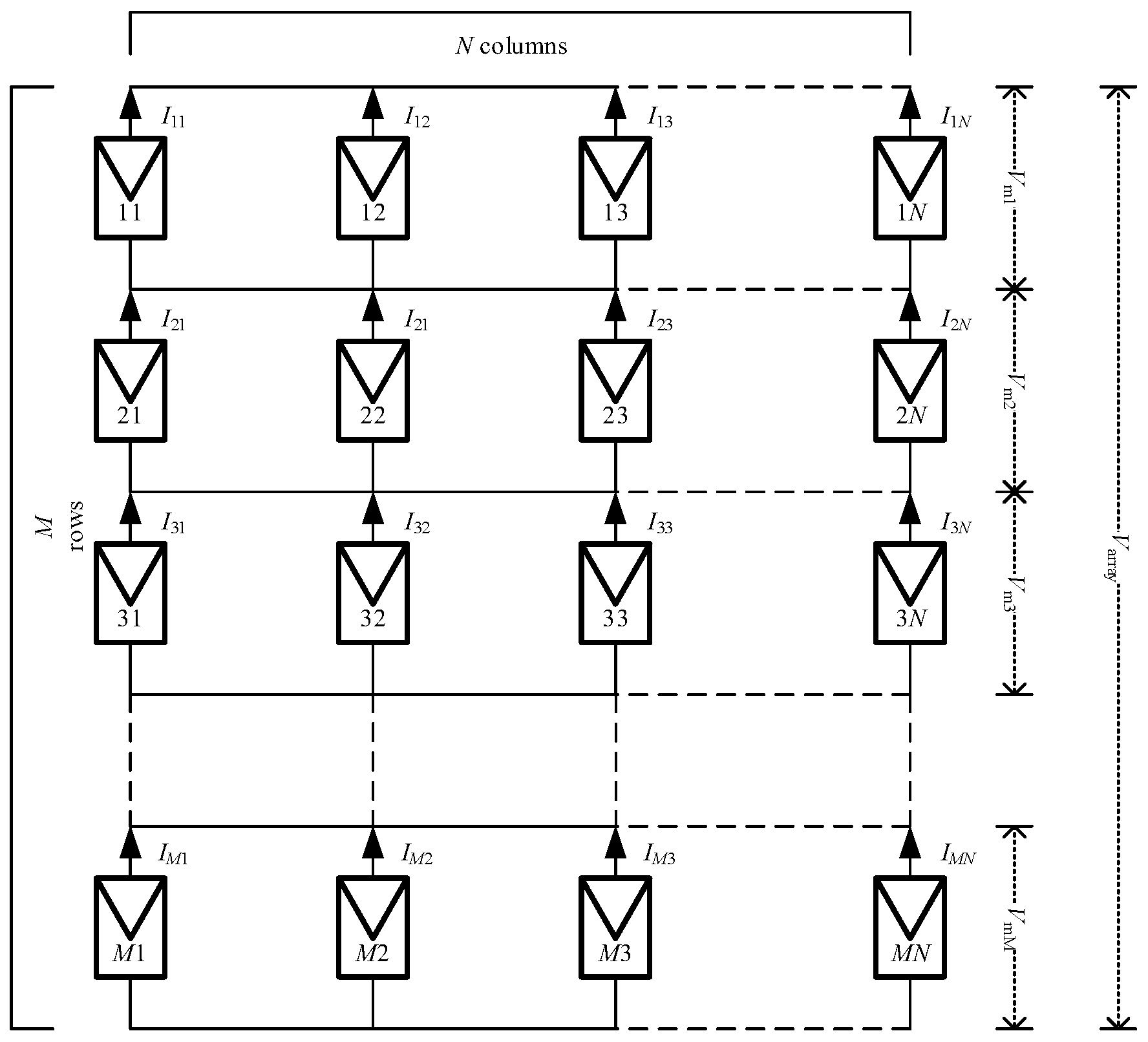
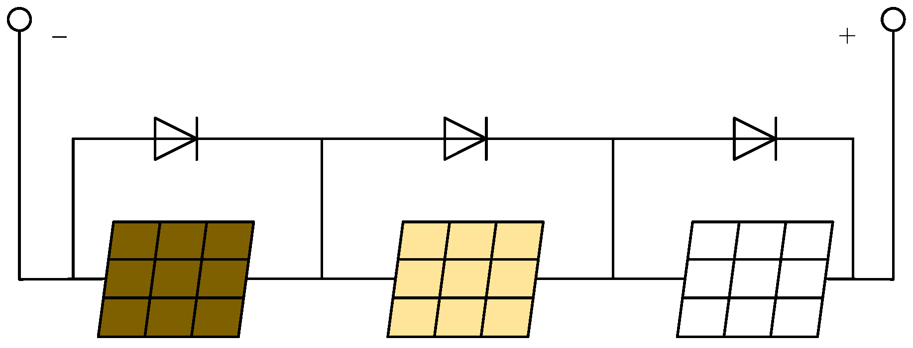
2.1. Photovoltaic Array TCT Structure Model

In the TCT structure, the modules of each row are connected in parallel, and the rows are connected in series. The TCT structure is determined as the connection scheme of the photovoltaic array. The TCT structure circuit of M × N is shown in Figure 1. The photovoltaic modules are numbered for easy identification, and the two numbers indicate the row number and column number of the module, respectively. For example, the component numbered ‘32’ is located in the third row and second column of the array.
According to Kirchhoff’s voltage law, the array voltage of the M-row TCT structure can be obtained [42].
V array = i = 1 M V m i
where V array is the total output voltage of the photovoltaic array, V m i is the maximum output voltage of the component in the ith row, and the output current of each node in the array can be obtained by Kirchhoff’s current law [42]:
I array = j = 1 N ( I i j I ( i + 1 ) j ) = 0 , i = 1 , 2 , 3 , , M 1
where I array is the output current of each node in the array, I i j is the output current of the component in column j of row i.
When the irradiance changes, the maximum power point voltage of the photovoltaic module changes little. The maximum power point current on the photovoltaic module can be considered to be approximately proportional to the irradiance value [50]. Therefore, it is concluded that in the TCT structure, the maximum power point voltage of the parallel component is not affected by the irradiance, and the sum of the maximum power point current of the parallel component is approximately proportional to the sum of the irradiance values. The current limiting I R i of ith row can be calculated as:
k i j = G i j G 0
I R i = j = 1 N k i j × I m , i = 1 , 2 , 3 , , M
where k i j is the ratio of irradiance value G i j of the photovoltaic module in row i and column j to irradiance (1000 W/m2) G 0 under standard conditions; I m is the maximum power point current output by the photovoltaic module at G 0 .
As the load current increases, rows that cannot reach a higher current value will be bypassed by the diode to protect the component from damage. The purpose of photovoltaic array reconfiguration is to balance the row current of the array and reduce the bypass, thereby increasing the output power.

2.2. The Characteristics of Photovoltaic Array under PSC

When the series photovoltaic module circuit is subjected to uneven illumination, the output I-U characteristic curve presents multiple knee platforms, and the output P-U characteristic curve presents a multi-peak phenomenon. As the current in the circuit increases, the blocked component will first reach the peak and form a peak point. When the working current continues to increase, the unblocked component will form a peak point again, which is the reason why the output characteristics of the photovoltaic array are multi-peaked when it is partially blocked. The photovoltaic series diagram of three photovoltaic modules is shown in Figure 2.
Under partial shading conditions, (1) the more the number of different irradiation levels, the more the peak value of the P-V curve, which makes the array not work near the maximum power point. (2) When the irradiance is not uniform, the total power of the array will decrease significantly. (3) When the photovoltaic array is subject to different shades, the larger the shading area, the lower the power generation.

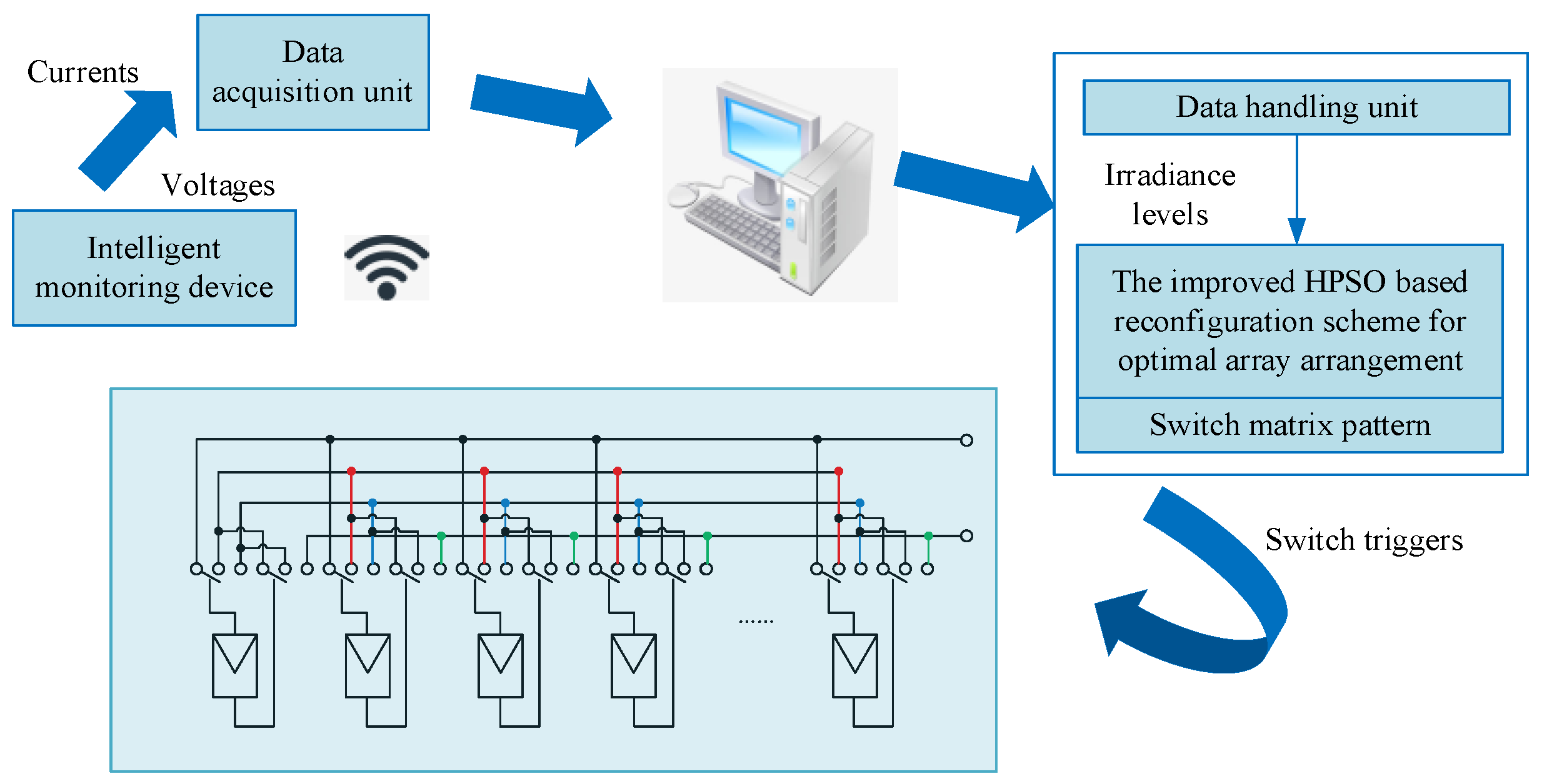
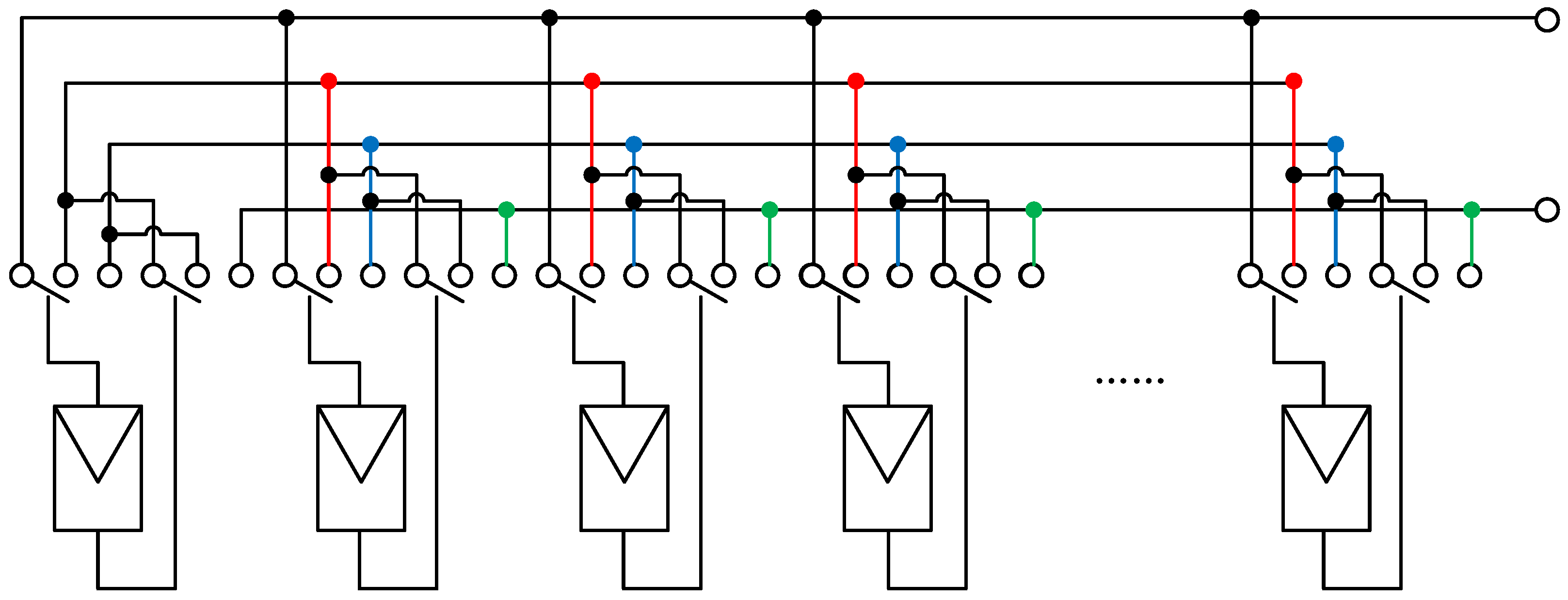
2.3. Electrical Array Reconfiguration

Electrical array reconfiguration (EAR) is an effective method to disperse the shadow of the photovoltaic array. A significant feature of the EAR is that the physical position of the photovoltaic modules in the photovoltaic array remains unchanged while the actual electrical connection changes. In this paper, the connection is changed by switching the photovoltaic module to reduce the irradiance difference of the photovoltaic array, and a controllable switching matrix is added for electrical reconnection. Figure 3 is the schematic structure of the photovoltaic array reconfiguration operation scheme based on the combination of switching matrix.

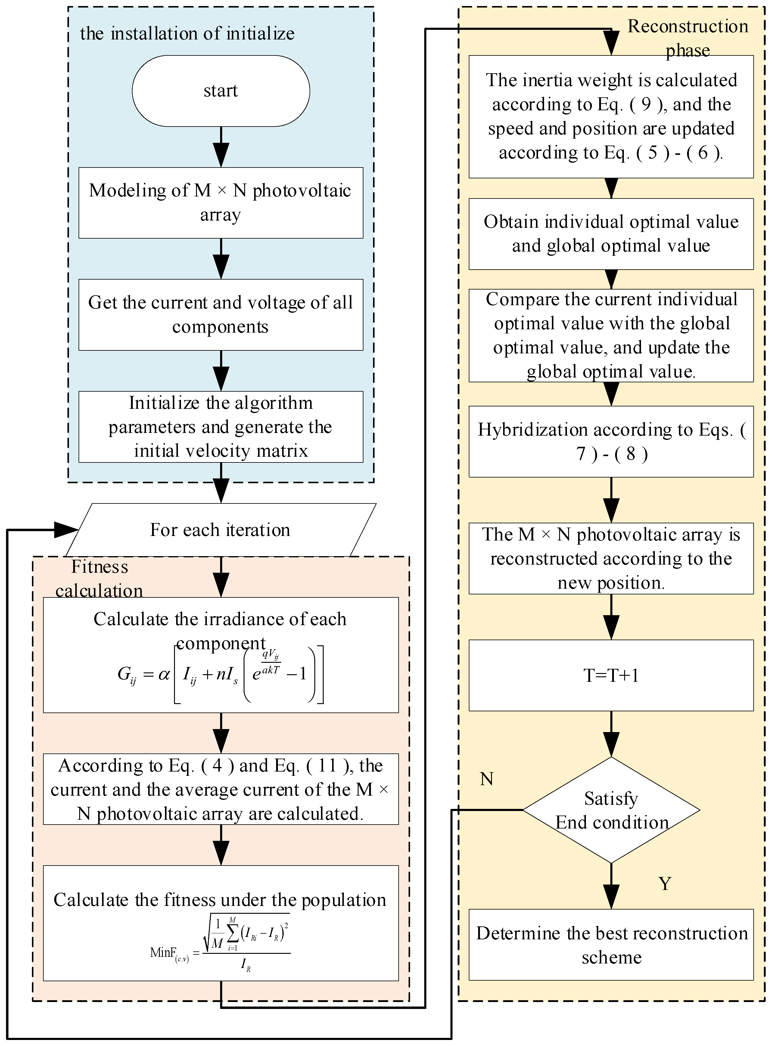
3. Photovoltaic Array Reconfiguration Method Based on Improved HPSO Combined with Coefficient of Variation

3.1. Particle Swarm Optimization Algorithm

Photovoltaic array reconfiguration requires effective optimization techniques, and only specific connections in a variety of possible combinations can evenly distribute shadows. The particle swarm optimization algorithm has a good effect on dealing with nonlinear stochastic optimization problems. Its basic idea is that biological populations (such as birds, fish, etc.) based on natural selection find the optimal solution by sharing information between populations.
The position and velocity of particles are updated by Equations (5) and (6) [51]:
v i = w × v i + c 1 r 1 ( p best x i ) + c 2 r 2 ( g best x i )
x i = x i + v i
where c 1 and c 2 are the learning factors, r 1 and r 2 are uniform random numbers between 0 and 1. w is the inertia weight, x and v represent the position and velocity of particles, respectively. p best is the best position for the individual, g best is the global optimal position.

3.2. Improved HPSO Algorithm

The traditional particle swarm optimization algorithm has the disadvantages of slow convergence speed and easy convergence to non-optimal solutions. In order to solve these problems, this paper uses an improved hybrid particle swarm optimization algorithm based on the shadow arrangement of photovoltaic arrays. The algorithm introduces the concept of hybridization in genetic algorithms. In each iteration, a specified number of particles are selected and placed in the hybridization pool. The particles in the pool are randomly hybridized to produce the same number of offspring particles, and the offspring particles are used instead of the parent particles. The position of the offspring is obtained by crossing the position of the parent:
n x = i × m x ( 1 ) + ( 1 i ) × m x ( 2 )
n v = m v ( 1 ) + m v ( 2 ) | m v ( 1 ) + m v ( 2 ) | | m v |
where m x and m v represent the position and velocity of the parent particle, respectively, n x and n v represent the position and velocity of the offspring particles, respectively. i is a random number between 0 and 1.
In order to make the global search and local search capabilities of the algorithm more balanced, a nonlinear decreasing weight method is used, as shown in Equation (9). In the early stage of iteration, the improved inertia weight decreases slowly, which is conducive to global search. In the late iteration, the weight decreases rapidly, maintaining the local search ability of the algorithm. This is not easy to fall into the local optimal solution, but it also improves the accuracy of the algorithm [52].
w = w end × r a n d × ( 1 cos ( π × t 2 × t max ) ) + w start × cos ( π × t 2 × t max )
where w start and w end are the initial value of inertia weight and the end value of inertia weight, respectively, t and t max are the current number of iterations and the maximum number of iterations, respectively.

3.3. Variation Coefficient Principle and Reconfiguration Execution Process

3.3.1. Principle of Coefficient of Variation

The mismatch problem of photovoltaic modules under partial shadow is mainly affected by the series part. In the TCT structure, the rows are connected in series. Therefore, the purpose of photovoltaic array reconfiguration based on TCT structure is to make the dispersion of current between rows as small as possible and extract power from the photovoltaic array as much as possible. In order to more accurately express the degree of dispersion between the row currents, the coefficient of variation between the row currents is used as the objective function. The coefficient of variation can reflect the degree of variation of the data, which is defined as:
C . V = 1 M i = 1 M ( I R i I R ) 2 I R × 100 %
where I R is the average value of the sum of row currents.
I R = 1 M i = 1 M I R i = 1 M i = 1 M j = 1 N k i j × I m

3.3.2. Implementation Process

The improved HPSO algorithm randomly starts to move in a variety of combinations and finally outputs the best connection method to effectively disperse the shadow of the photovoltaic array. The algorithm is easy to program, fast, and can achieve the optimal solution in a short time, which reduces the possibility of convergence to the non-optimal solution to a certain extent. In the array reconfiguration based on the improved HPSO algorithm, the number of particles represents the number of components of the photovoltaic array, the position of the particles represents the electrical arrangement of the photovoltaic array, and the objective function is the coefficient of variation of the row current. Firstly, the algorithm collects the parameters, such as the light intensity of the photovoltaic array, and then changes the electrical connection of the array according to its own dynamic mechanism until the scheme with the smallest coefficient of variation is found and the arrangement of the photovoltaic array is output.
Usually, the switching matrix is inserted between the photovoltaic modules for global reconfiguration. Figure 4 shows the switching matrix structure of the photovoltaic modules in the M-row N-column. The switching matrix changes the electrical connection between the components according to the optimal reconfiguration scheme obtained by the algorithm and finally realizes the array reconfiguration.
The number of switches required for the proposed configuration is 2 × M × N single-pole multi-throw switches, 24 switches for 4-row 3-column arrays, and 162 switches for 9-row 9-column arrays. For ease of understanding, the array reconfiguration process based on the improved HPSO algorithm is shown in Figure 5.
The reconfiguration steps are
The first step is to initialize the M × N array and set the algorithm parameters.
The second step is to generate a population matrix [43], and the initial velocity formula of the particles is calculated as follows:
v i = 1 + r o u n d ( r a n d (   ) × 8 )
The third step is irradiance calculation. The irradiance is obtained using the voltage and current data of the measuring component [43]. The specific calculation is as follows:
G i j = α [ I i j + n I s ( e q V i j a k T 1 ) ]
where α is the proportional coefficient between current and light intensity, I s is the saturation current of the cell diode, a is the characteristic factor; q , k , T are the electron charge constant, Boltzmann constant, and working temperature, respectively.
The fourth step is to construct an objective function based on the improved HPSO. The smaller the coefficient of variation, the higher the output power obtained by the array. Taking the minimum fitness as the judgment condition of the best reconfiguration scheme, the calculation formula is as follows:
MinF ( c . v ) = 1 M i = 1 M ( I R i I R ) 2 I R
where I R i is the current limit of the ith row, I R is the mean row current.
In the fifth step, the nonlinear decreasing inertia weight is used to update the particle velocity and position, and the global optimal value is updated. The hybrid operation is performed according to Equations (7) and (8), and the reconstructed photovoltaic array is generated according to the new position to determine whether the end condition is satisfied. In the sixth step, the end condition is to meet the maximum number of iterations and output the best reconfiguration scheme after meeting the conditions.

4. Result and Discussion

To evaluate the effectiveness of the proposed scheme, the improved HPSO is compared with TCT and Zig-Zag in a 4 × 3 array and with TCT, CS, and improved SuDoKu in a 9 × 9 array. The results demonstrate the superiority of the proposed method in dispersing shadows and generating the highest power value is proved. The photovoltaic array model is constructed using the Matlab/Simulink software. Table 1 presents the rated parameters of photovoltaic modules under standard conditions.

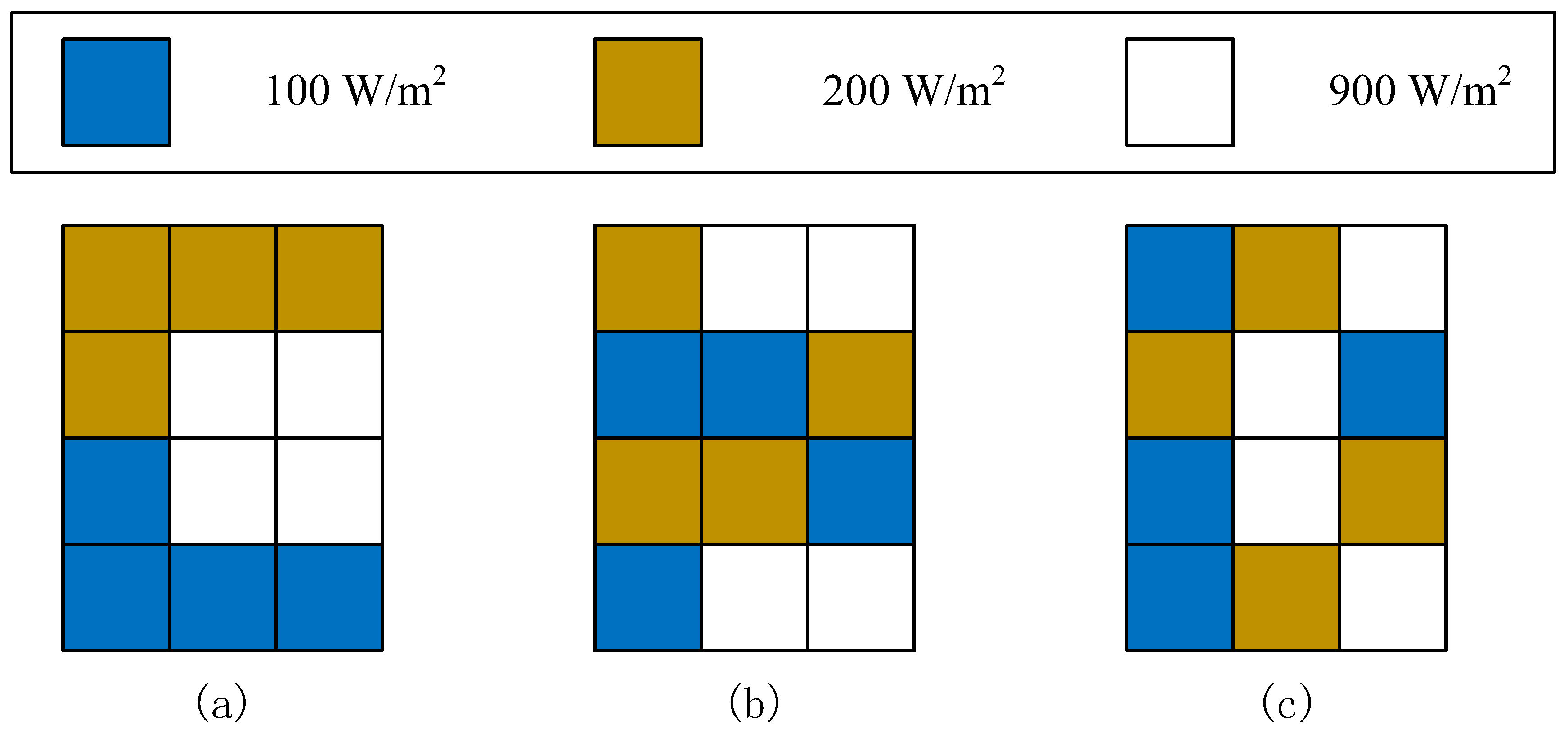
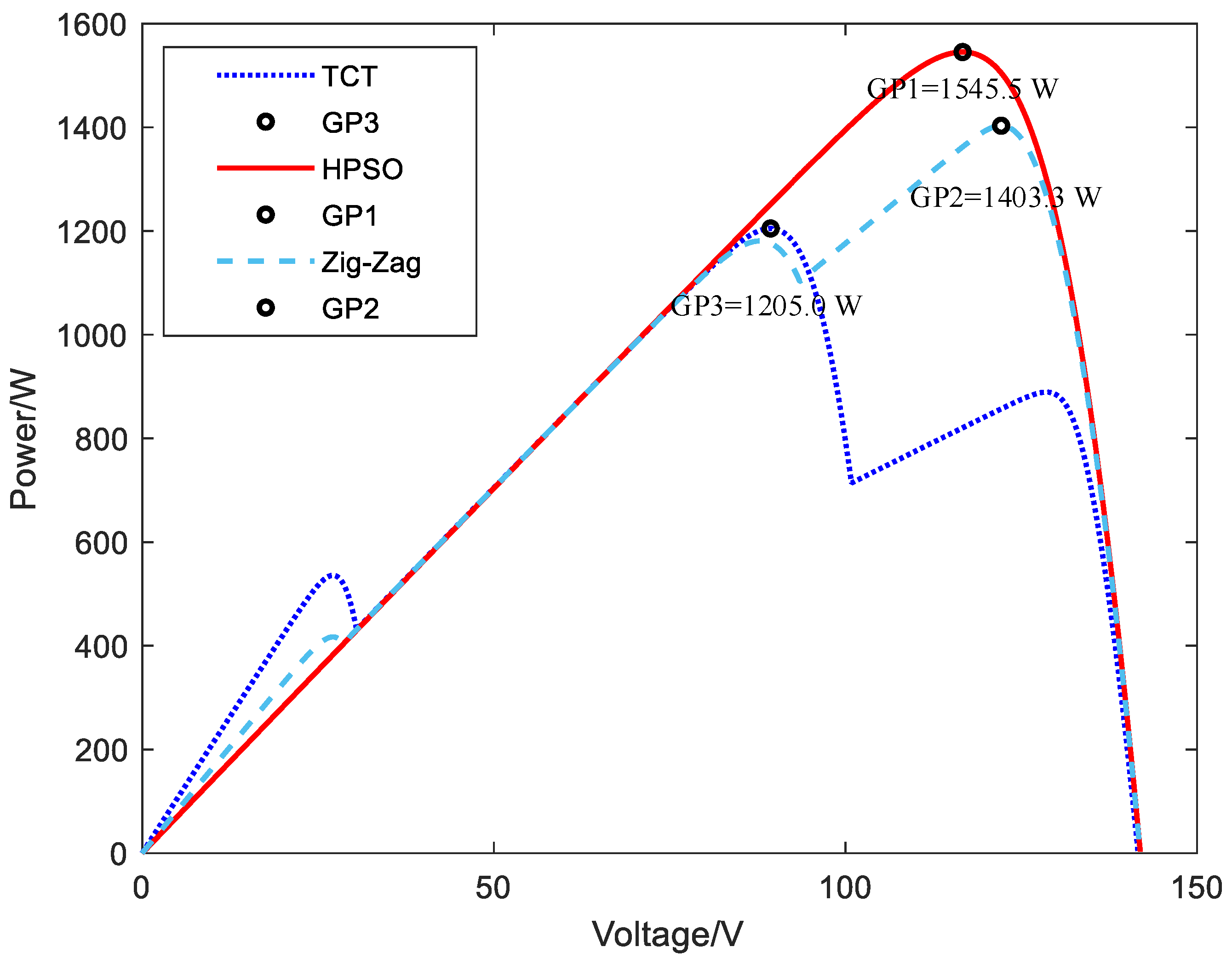
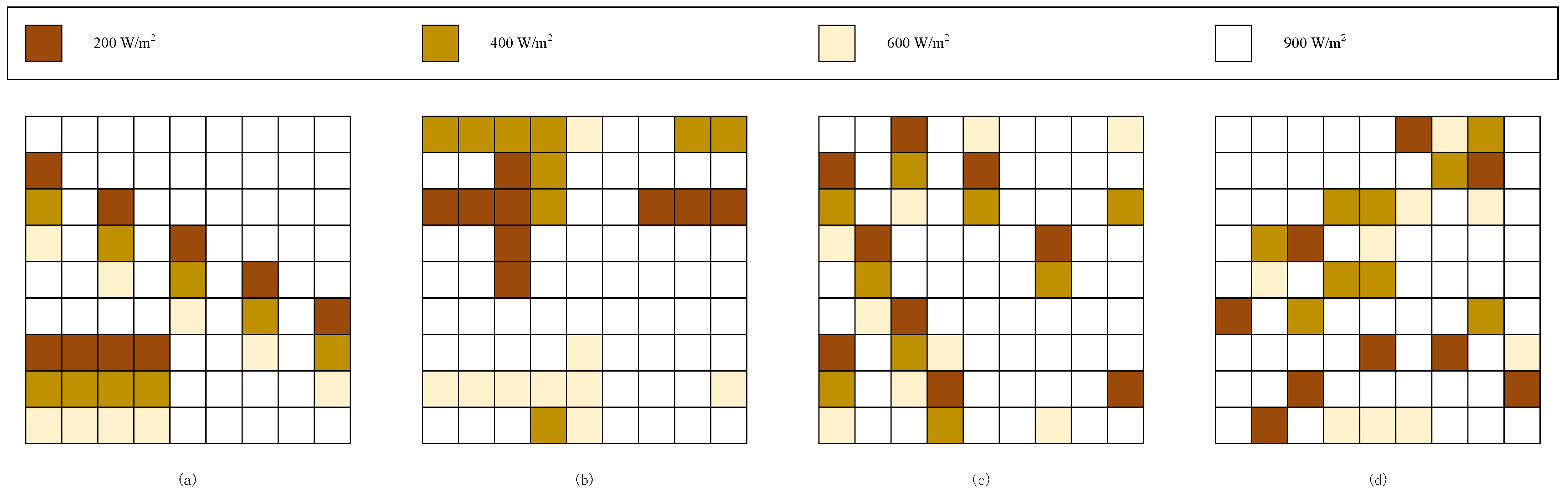
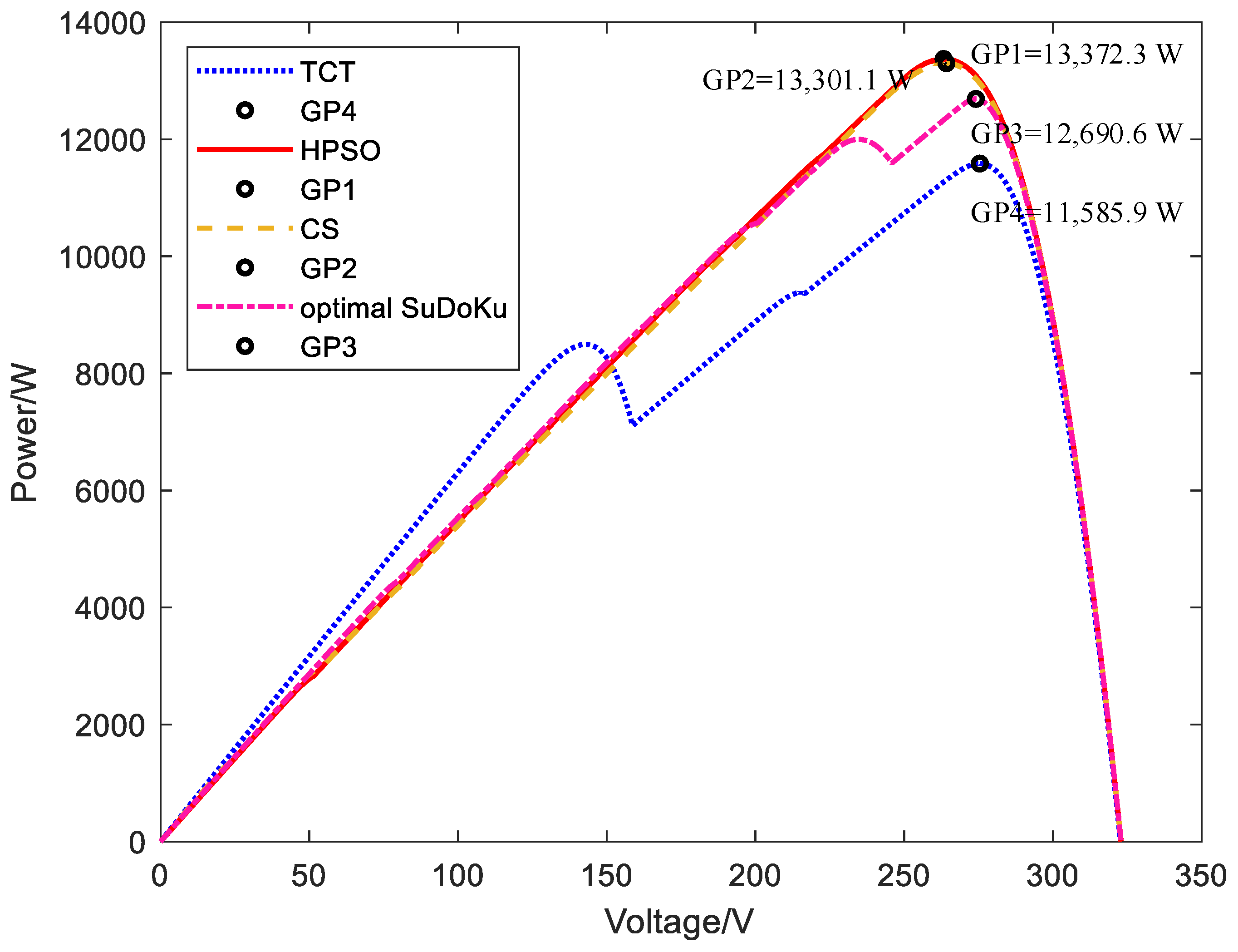
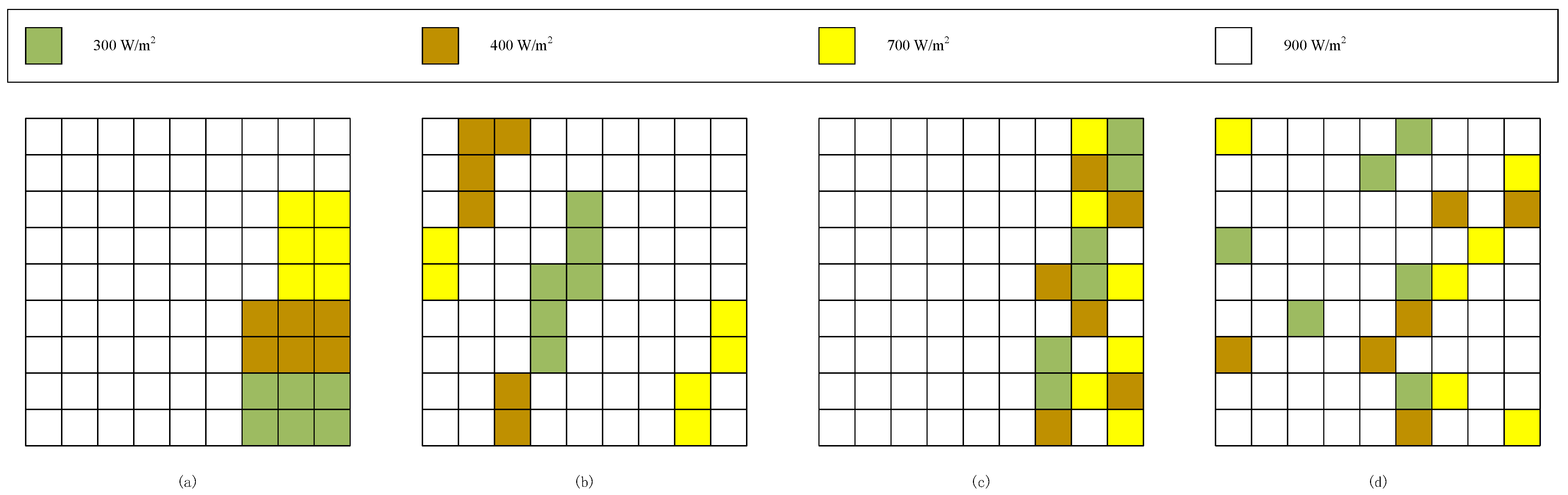
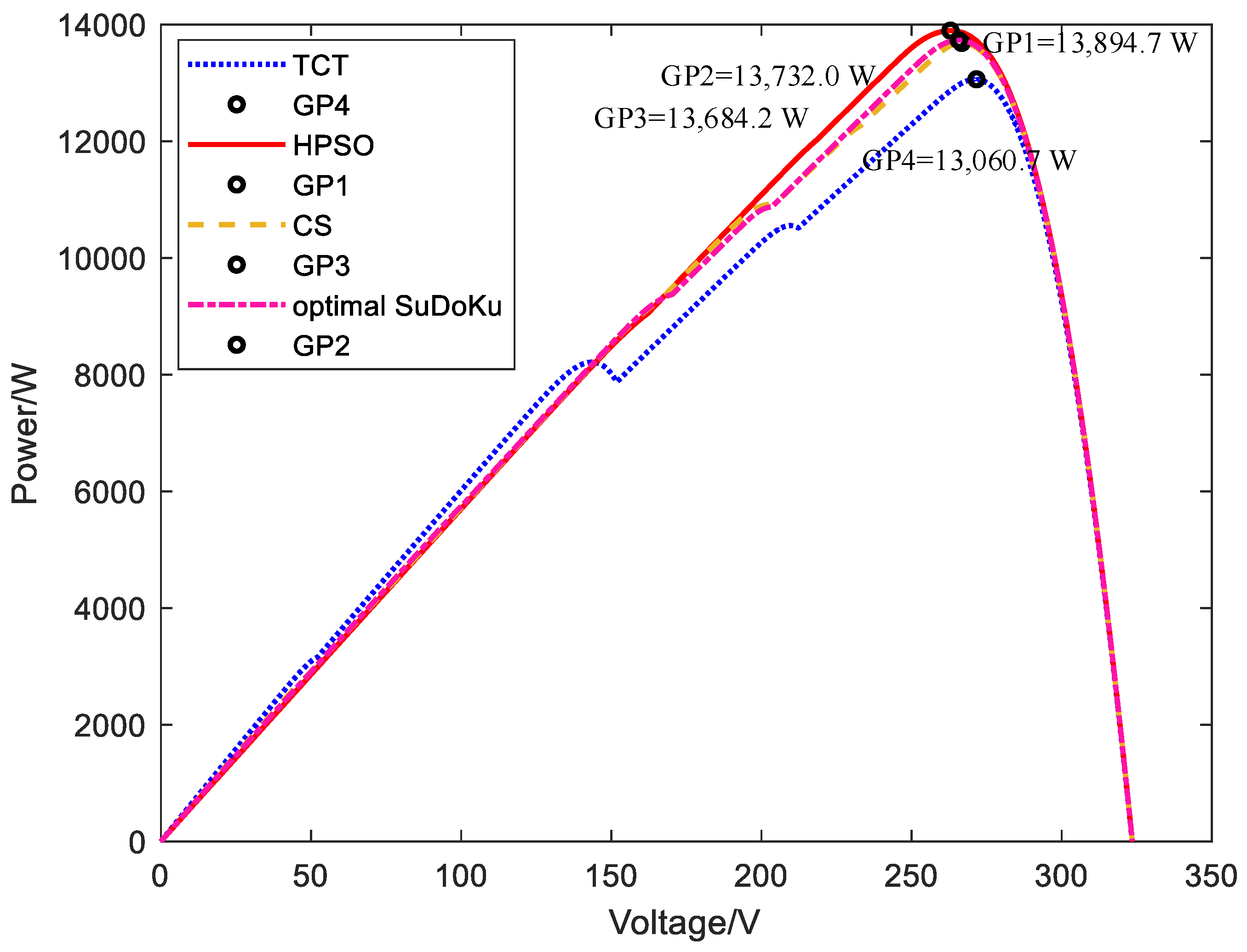
4.1. Non-Square Matrix Simulation Research

Shadow mode 1: Semi-enclosed shadow
In this mode, the shadow mode of the photovoltaic array is shown in Figure 6. The irradiance of the component is 100 W/m2, 200 W/m2, and 900 W/m2. Figure 6a–c are the shadow distribution of the TCT scheme, Zig-Zag scheme, and improved HPSO scheme, respectively.
According to Equation (4), the IR1~IR4 before reconfiguration are 0.6 Im, 2 Im, 1.9 Im, and 0.3 Im, respectively, and the IR1~IR4 after reconfiguration of the improved HPSO scheme is 1.2 Im. The coefficient of variation decreased from 63.19% to 0, which balanced the row current. The P-V characteristic curves corresponding to the TCT, Zig-Zag, and improved HPSO methods are shown in Figure 7.
It can be seen from the simulation results that the curve before reconfiguration exhibits multi-peak characteristics. The curve after reconfiguration using the improved HPSO scheme is smooth and exhibits single-peak characteristics, and the output power is the highest. The maximum output power of the improved HPSO scheme is 1021.3 W, which is 26.35% higher than that of the TCT scheme and 26.35% higher than that of the Zig-Zag scheme.
Shadow mode 2: Concentrated shadow
In this mode, the irradiance of the array is 300 W/m2, 600 W/m2, and 900 W/m2, and the shadows in the 2–4 rows of the array are different. The specific TCT mode is shown in Figure 8a. The shadow distribution of the Zig-Zag scheme and improved HPSO scheme is shown in Figure 6b,c, respectively.
According to Equation (4), the IR1~IR4 before reconfiguration are 2.7 Im, 1.8 Im, 1.8 Im, and 0.9 Im, respectively, and the IR1~IR4 after reconfiguration of the improved HPSO scheme are 1.8 Im. The coefficient of variation decreased from 35.36% to 0, which balanced the row current. The P-V characteristic curves corresponding to TCT, Zig-Zag, and improved HPSO methods are shown in Figure 9.
From the simulation results, it can be seen that there are multiple peak points in the P-V curve before reconfiguration. After improved HPSO reconfiguration, the number of peak points becomes one, and the curve is smoother, which is convenient for maximum power point tracking in the later stage and improves the maximum output power.
The maximum output power of the proposed improved HPSO scheme is 1545.5 W, which is 28.26% higher than that of the TCT scheme before reconfiguration (1205.0 W) and 10.13% higher than that of the Zig-Zag scheme (1403.3 W).

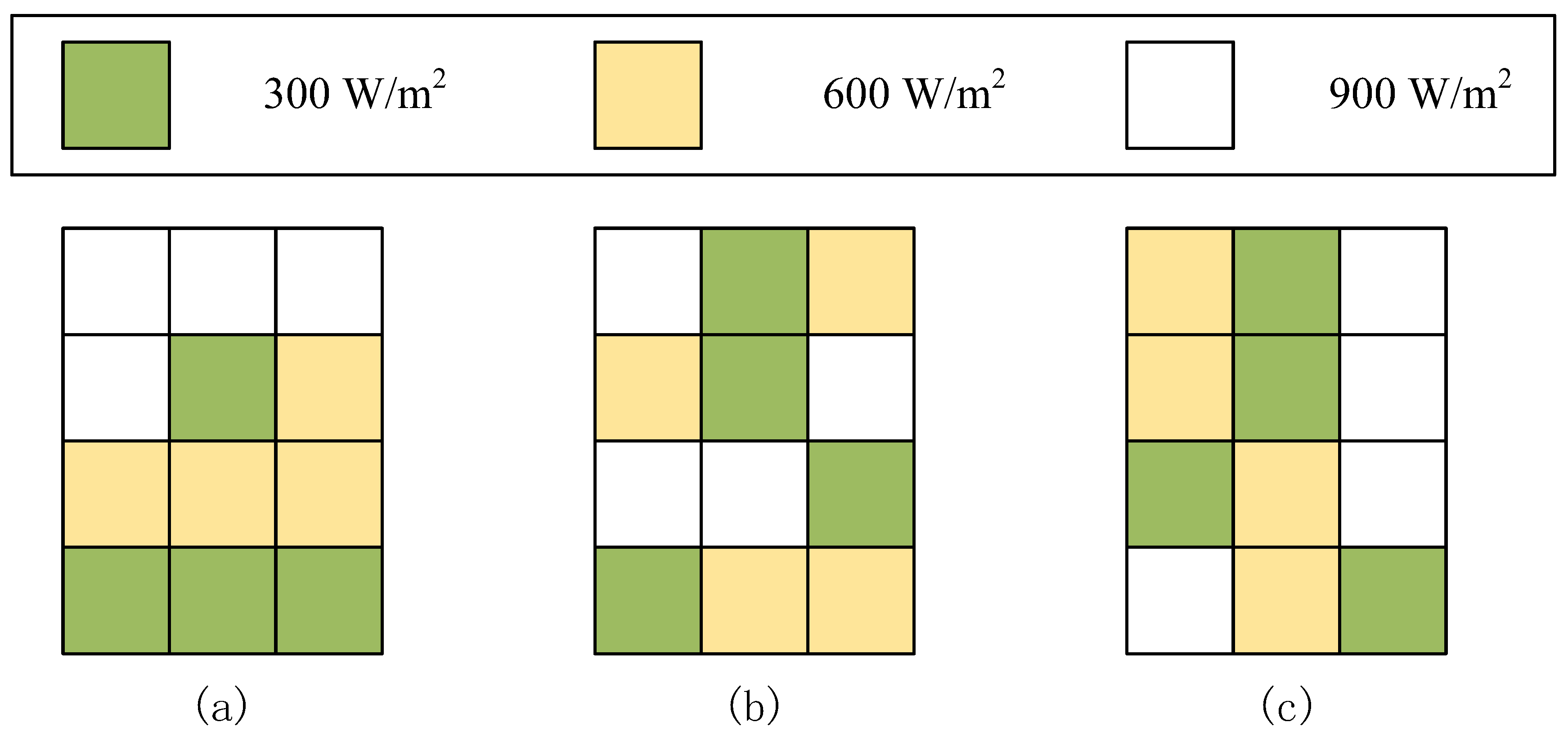
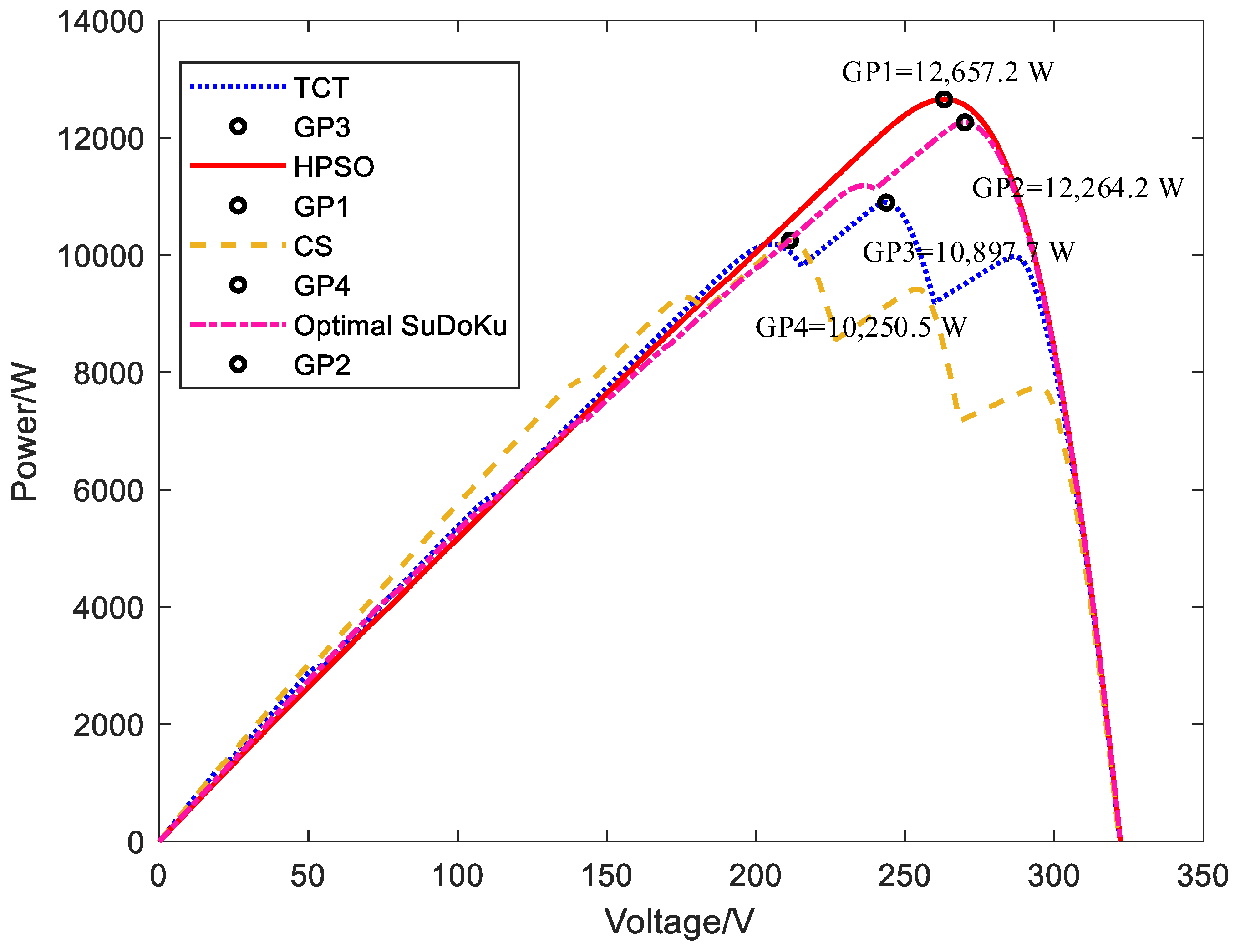
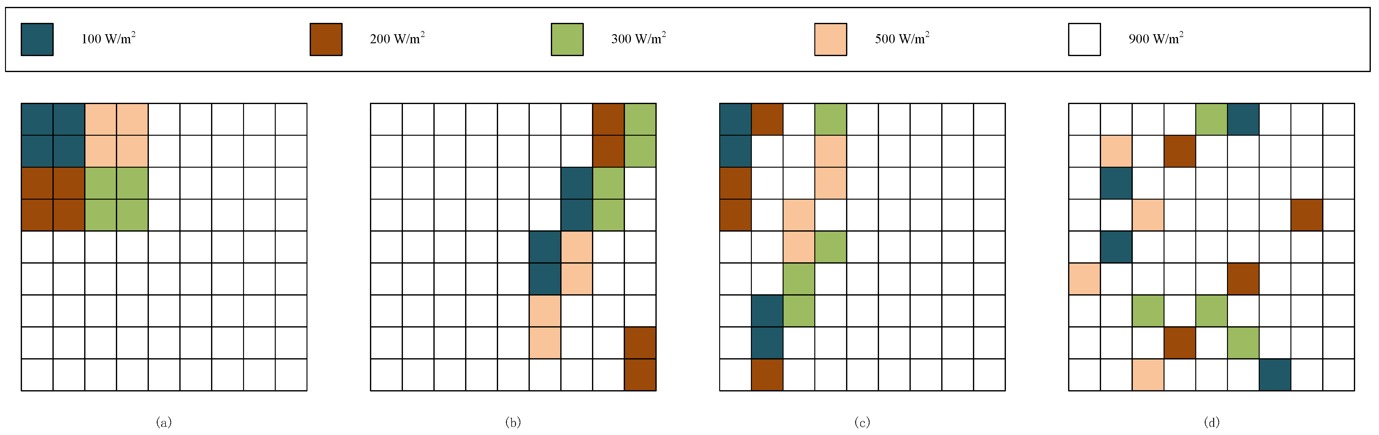
4.2. Simulation of Square Matrix

Shadow mode 3: Scattered and bottom-concentrated shadows
In this mode, the photovoltaic module is irradiated by 200 W/m2, 400 W/m2, 600 W/m2, and 900 W/m2. The three shadows form scattered shadows in the middle of the array and concentrated shadows in the lower left corner. The scattered shadow modes of the TCT scheme, CS scheme, improved SuDoKu scheme, and improved HPSO scheme are shown in Figure 10a–d.
According to Equation (4), the IR1~IR9 before reconfiguration are 8.1 Im, 7.4 Im, 6.9 Im, 6.6 Im, 6.6 Im, 6.6 Im, 4.5 Im, 5.8 Im, and 6.9 Im, respectively, and the IR1~IR9 after reconfiguration of the improved HPSO scheme are 6.6 Im, 6.9 Im, 6.5 Im, 6.6 Im, 6.8 Im, 6.4 Im, 6.4 Im, 6.7 Im, and 6.5 Im, respectively. The coefficient of variation C.V after reconfiguration is reduced from 14.39% to 2.47%, and the degree of row current dispersion is the smallest.
The P-V characteristic curve before and after reconfiguration is shown in Figure 11.
The simulation results show that the maximum output power of the proposed improved HPSO scheme is 12,657.2 W, which is 16.15% higher than the maximum output power of 10,897.7 W before reconfiguration, 23.48% higher than the maximum output power of 10,250.5 W of the CS scheme, and 3.2% higher than the maximum output power of 12,264.2 W of the improved SuDoKu scheme. The power curve before reconfiguration shows multiple peaks, and there is only one maximum peak in the power curve after reconfiguration.
Shadow mode 4: Short-width shadow
In this case, the array has five irradiances, as shown in Figure 12a–d giving the scattered shadow modes of the TCT scheme, CS scheme, improved SuDoKu scheme, and improved HPSO scheme, respectively.
According to Equation (4), IR1~IR9 before reconfiguration are 5.7 Im, 5.7 Im, 5.5 Im, 5.5 Im, 8.1 Im, 8.1 Im, 8.1 Im, and 8.1 Im, respectively. After the reconfiguration of the improved HPSO scheme, IR1~IR9 are 6.7 Im, 7 Im, 7.3 Im, 7 Im, 7.3 Im, 7 Im, 6.9 Im, 6.8 Im, and 6.9 Im, respectively. After reconfiguration, the coefficient of variation decreases from 17.80% to 2.74%, and the current becomes more balanced after reconfiguration. The P-V characteristic curves before and after reconfiguration are shown in Figure 13.
From the simulation results, the maximum output power of the improved HPSO scheme is the highest, which is 13,372.3 W, which is 15.42% higher than the maximum output power of the TCT scheme before reconfiguration (11,585.9 W), 0.54% higher than the maximum output power of the CS scheme (13,301.1 W), and 5.37% higher than the maximum output power of the improved SuDoKu scheme (12,690.6 W). After the reconfiguration of the improved HPSO scheme, the P-V characteristic curve of the array changes from multi-peak to single-peak.
Shadow mode 5: Long and narrow shadow
In this case, the right part of the array is exposed to 300 W/m2, 400 W/m2, and 700 W/m2 illumination, and the remaining modules in the array are exposed to 900 W/m2 irradiation. In this mode, the scattered shadow modes of the TCT scheme, CS scheme, improved SuDoKu scheme, and improved HPSO scheme are shown in Figure 14a–d, respectively.
According to Equation (4), the IR1~IR9 before reconfiguration are 8.1 Im, 8.1 Im, 7.7 Im, 7.7 Im, 7.7 Im, 7.7 Im, 6.6 Im, 6.6 Im, 6.6 Im, 6.3 Im, 6.3 Im, and 6.3 Im, respectively. The IR1~IR9 after reconfiguration of the improved HPSO scheme are 7.3 Im, 7.3 Im, 7.1 Im, 7.3 Im, 7.3 Im, 7.3 Im, 7 Im, 7.1 Im, 7.3 Im, and 7.4 Im, respectively. The coefficient of variation before and after reconfiguration is reduced from 9.99% to 1.72%, and the row current is more balanced. The P-V characteristic curve before and after reconfiguration is shown in Figure 15.
The simulation results show that the maximum output power of the proposed improved HPSO scheme reaches 13,894.7 W, which is 6.39% higher than the maximum output power of the TCT scheme before reconfiguration (13,060.7 W), 1.54% higher than the maximum output power of the CS scheme (13,684.2 W), and 1.18% higher than the maximum output power of the improved SuDoKu scheme (13,732.0 W). The curve of the improved HPSO scheme is smoother, and the reconfiguration effect is the best. The lower power increase in shadow mode 5 is because the initial row irradiance difference is not much different, the shadow mode is narrow, the range of reconfiguration is limited, and shadow mode 3 is wider. The benefits of array reconfiguration are more obvious.

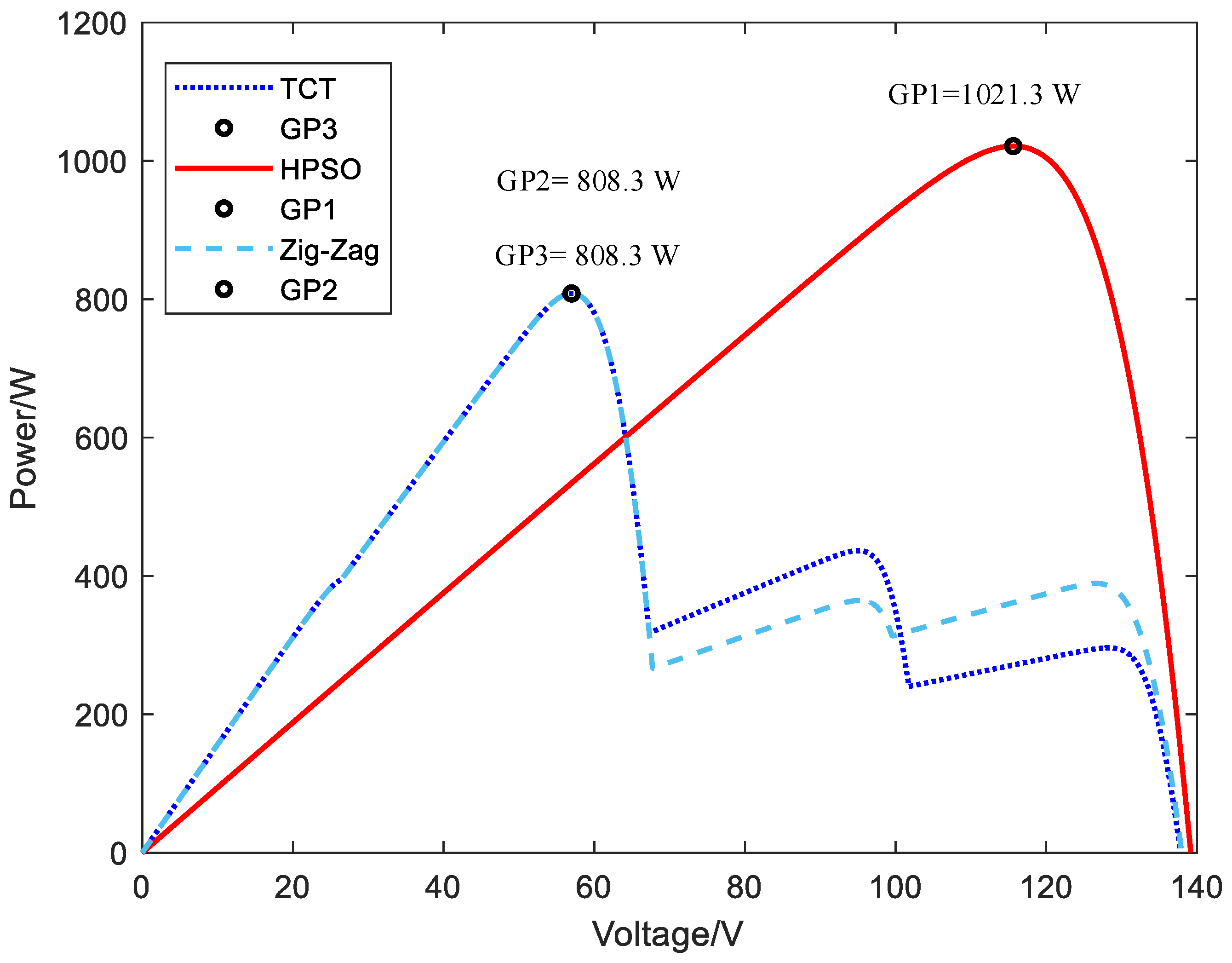
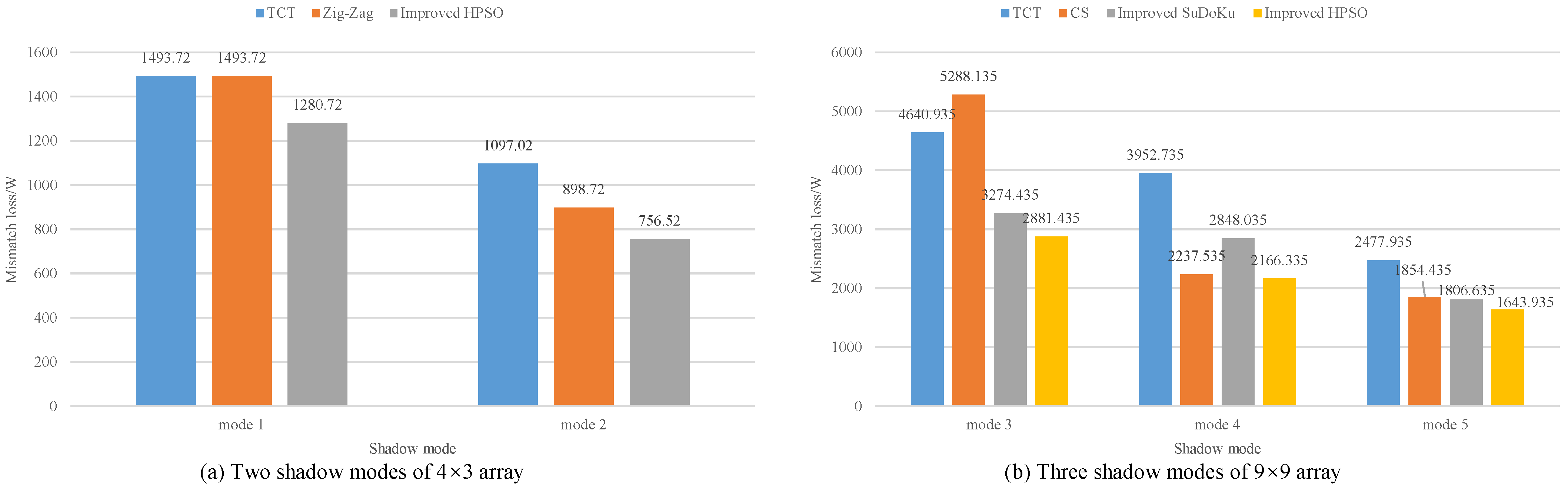
4.3. Performance Study

The advantages of the proposed scheme are evaluated from three aspects: mismatch loss, power increase percentage, and fill factor.
The mismatch loss is defined as the difference between the maximum power PGMPP (US) of the arrays without shadows array and the maximum power PGMPP (PS) of the partially shaded array.
P M = P GMPP ( US ) P GMPP ( PS )
The fill factor is an important parameter to measure the output performance of the array. The higher the value, the better the performance. It is defined as the ratio of the maximum power VM × IM of the array under shadow conditions to the product of the open circuit voltage VOC and the short circuit current ISC.
F F = V M × I M V OC × I SC
The power enhancement percentage is defined as the ratio of the difference between the maximum power before and after reconfiguration to the maximum power before reconfiguration.
P en = P after P TCT P TCT × 100 %
where PTCT and Pafter are the global maximum power of the array output before and after reconfiguration.
According to the analysis and calculation, the performance of the five shadow modes is shown in Table 2. It can be seen that the proposed scheme has the smallest mismatch loss, the highest fill factor, and the best performance.

4.4. Discussion on the Performance of Various Methods

Through theoretical evaluation and simulation of the electrical characteristic curve, the proposed improved HPSO scheme produces the highest power, showing effective dispersion ability to the shadow. In order to evaluate the overall performance improvement of the proposed improved HPSO reconfiguration scheme under partial shading conditions, it can be seen from Figure 16 that compared with TCT, Zig-Zag, CS, and improved Sudoku schemes, the improved HPSO reconfiguration scheme proposed in this paper has a lower mismatch loss and the highest output power in shadow modes 1–5, indicating that the reconfiguration scheme proposed in this paper has a better performance.
The orange bar in Figure 17 represents the FF evaluation value of the PV array after different reconfiguration methods under different pattern shadows. This shows that compared with other technologies, the fill factor of the PV array with improved HPSO scheme in shadow modes 1–5 are 77.8%, 76.9%, 72.4%, 72.1%, and 73.8%, respectively, which means that higher effectiveness is obtained.
In particular, compared with the TCT before reconfiguration, in shadow modes 1–5, the power increased by 26.35%, 28.26%, 16.15%, 15.42%, and 6.39%, respectively. For the CS scheme in shadow mode 3, the generation success rate of the improved HPSO scheme is significantly enhanced. Compared with the Zig-Zag scheme, the improved HPSO scheme has significantly higher power under shadow modes 1 and 2. In addition, in shadow mode 4, the power of the improved HPSO scheme is significantly higher than that of the improved SuDoKu technology. In summary, compared with the TCT, Zig-Zag, CS, and improved Sudoku schemes, the proposed improved HPSO scheme can generate more power in the five shadow modes.

4.5. The Strengths, Limitations, and Significance of the Proposed Method in Real-Life Scenarios

The strengths: The proposed method can effectively disperse the local shadows in actual operation and provide the optimal reconfiguration scheme for the switch matrix. This method takes a short time and can cope with real-time changing shadows in real scenes.
The limitations: The proposed method requires switches and sensors, which will increase some costs. If in the scene of uniform irradiance without reconfiguration, some hardware devices are idle.
The significance: The proposed method can effectively improve the maximum output power and reduce unnecessary energy waste. Through the proposed reconfiguration scheme, more energy can be saved, and more annual benefits can be obtained.

5. Conclusions

This paper proposes a method for reconfiguring photovoltaic arrays using an improved hybrid particle swarm optimization algorithm (HPSO) to minimize the impact of local shadows. The proposed scheme can effectively maximize the GMP extracted from the photovoltaic system and offers a simple solution to alleviate the limitations caused by complex physical array relocation methods such as total-cross-tied (TCT) and Sudoku.
  • The proposed method is suitable for square matrices and non-square matrices. Under the five shadow modes discussed, the multi-peak problem in P-V characteristics is effectively solved. The curve is smooth and tends to single peak characteristics.
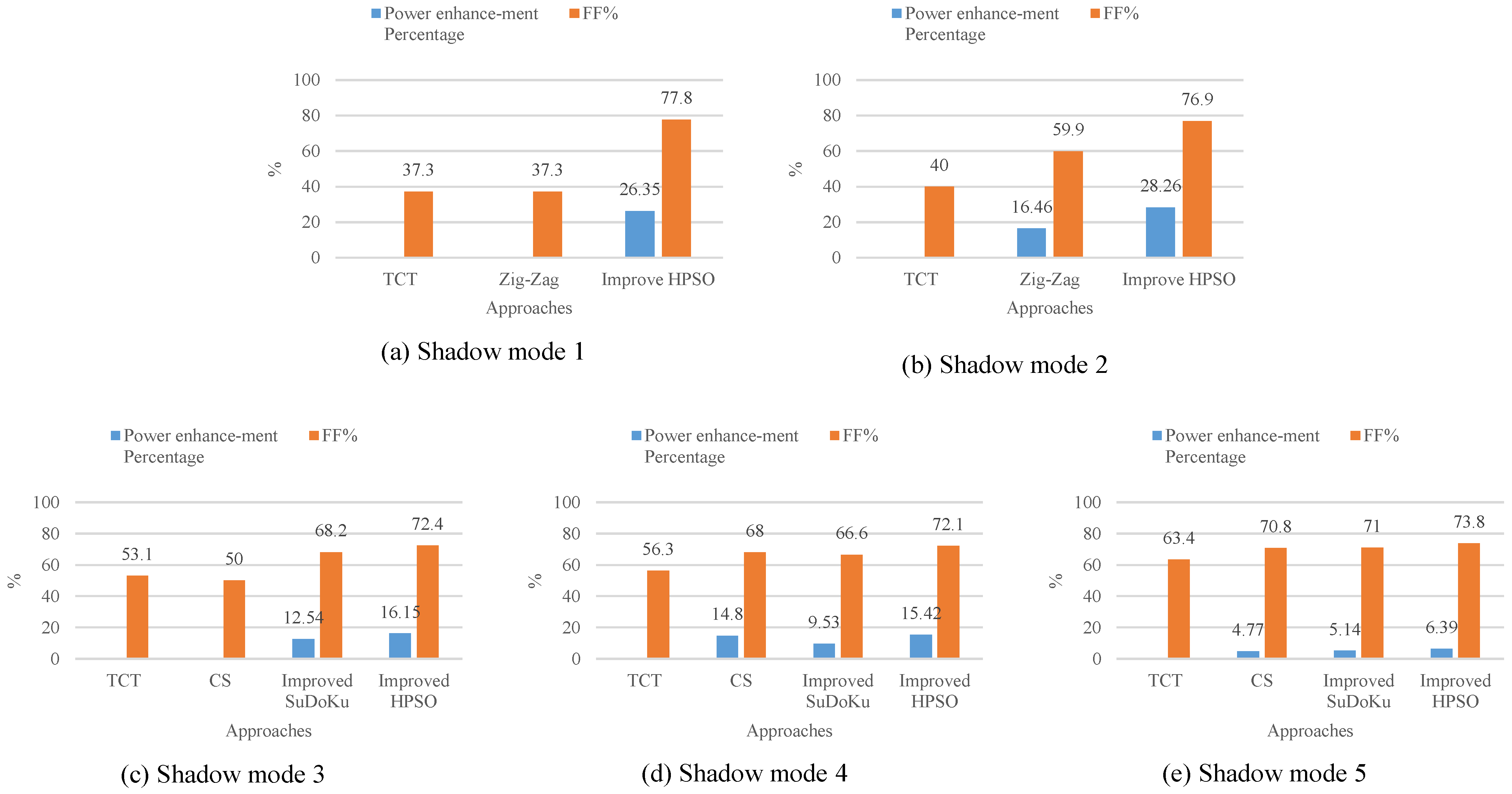
  • The maximum output power after reconfiguration is increased by 6.39%~28.26%, which is the best compared with other schemes in this paper. In terms of performance, the proposed reconfiguration scheme has a smaller mismatch loss and a higher fill factor.
  • In the 4 × 3 non-square matrix, the average mismatch loss is 1018.62 W, and the average fill factor is 0.7735, which is better than the Zig-Zag scheme. In the 9 × 9 square matrix, the average mismatch loss is 2230.568 W, and the average fill factor is 0.728, which is better than the CS scheme and the improved SuDoKu scheme.
Therefore, the obtained results confirm the ability and superiority of the proposed HPSO in the optimization and reconfiguration of shading PV arrays. The proposed reconfiguration scheme can effectively alleviate the impact of local shadows and can deal with complex shadow scenes and large photovoltaic arrays. It has practical value and facilitates maximum power point tracking in the later stage.
Future work will consider real-time changes in cloud movement and dust accumulation and the impact of larger PV arrays and maximum power point tracking after PV array reconfiguration. The authors intend to implement these considerations in future research.

Author Contributions

S.H. and W.Z. were involved in the full process of producing this paper, including conceptualization, methodology, modeling, validation, visualization, and preparing the manuscript. All authors have read and agreed to the published version of the manuscript.

Funding

This research was funded by the State Grid Shanghai Electric Power Company Science and Technology Project, grant number H2020-073.

Data Availability Statement

The data presented in this study are available upon request from the corresponding author.

Acknowledgments

This research was carried out within the photovoltaic array reconfiguration and improve the output power, H2020-073, State Grid Shanghai Electric Power Company—science and Technology Project.

Conflicts of Interest

The authors declare no conflict of interest.

References

  1. Li, G.; Li, C.; Wang, Y.; He, Y. Maximum power point tracking method for photovoltaic cells under partial shading conditions. Electr. Meas. Instrum. 2023, 60, 45–52. [Google Scholar] [CrossRef]
  2. Zhou, X.; Chen, S.; Lu, Z.; Huang, Y.; Ma, S.; Zhao, Q. Technology features of the new generation power system in China. Proc. CSEE 2018, 38, 1893–1904, 2205. [Google Scholar] [CrossRef]
  3. Zhuo, Z.; Zhang, N.; Xie, X.; Li, H.; Kang, C. Key technologies and developing challenges of power system with high proportion of renewable energy. Autom. Electr. Power Syst. 2021, 45, 171–191. [Google Scholar]
  4. Malathy, S.; Ramaprabha, R. Reconfiguration strategies to extract maximum power from photovoltaic array under partially shaded conditions. Renew. Sustain. Energy Rev. 2018, 81, 2922–2934. [Google Scholar] [CrossRef]
  5. Shi, M.; Yin, R.; Jiang, W.; Wang, Y.; Hu, P.; Hu, K. Overview of flexible grid-connected cluster control technology for distributed photovoltaic. Electr. Meas. Instrum. 2021, 58, 1–9. [Google Scholar] [CrossRef]
  6. Kang, C.; Du, E.; Li, Y.; Zhang, N.; Chen, Q.; Guo, H.; Wang, P. Key Scientific problems and research framework for carbon perspective research of new power systems. Power Syst. Technol. 2022, 46, 821–833. [Google Scholar] [CrossRef]
  7. Zhang, M.; Chen, Z. Reconfiguration scheme of photovoltaic array based on minimum equalization difference. Electr. Power Autom. Equip. 2021, 41, 33–38. [Google Scholar] [CrossRef]
  8. Belhachat, F.; Larbes, C. Modeling, analysis and comparison of solar photovoltaic array configurations under partial shading conditions. Sol. Energy 2015, 120, 399–418. [Google Scholar] [CrossRef]
  9. Guo, L.; Meng, Z.; Sun, Y.; Wang, L. A modified cat swarm optimization based maximum power point tracking method for photovoltaic system under partially shaded condition. Energy 2018, 144, 501–514. [Google Scholar] [CrossRef]
  10. Sen, T.; Pragallapati, N.; Agarwal, V.; Kumar, R. Global maximum power point tracking of PV arrays under partial shading conditions using a modified particle velocity-based PSO technique. IET Renew. Power Gener. 2018, 12, 555–564. [Google Scholar] [CrossRef]
  11. Kumar, N.; Hussain, I.; Singh, B.; Panigrahi, B.K. MPPT in Dynamic Condition of Partially Shaded PV System by Using WODE Technique. IEEE Trans. Sustain. Energy 2017, 8, 1204–1214. [Google Scholar] [CrossRef]
  12. Yang, B.; Yu, T.; Shu, H.; Zhu, D.; An, N.; Sang, Y.; Jiang, L. Energy reshaping based passive fractional-order PID control design and implementation of a grid-connected PV inverter for MPPT using grouped grey wolf optimizer. Sol. Energy 2018, 170, 31–46. [Google Scholar] [CrossRef]
  13. Yang, B.; Yu, T.; Shu, H.; Zhu, D.; An, N.; Sang, Y.; Jiang, L. Perturbation observer based fractional-order sliding-mode controller for MPPT of grid-connected PV inverters: Design and real-time implementation. Control Eng. Pract. 2018, 79, 105–125. [Google Scholar] [CrossRef]
  14. Guillermo, V.; Francesc, G.; Robert, P. Grid-connected PV systems energy extraction improvement by means of an Electric Array Reconfiguration (EAR) strategy: Operating principle and experimental results. In Proceedings of the 2008 IEEE Power Electronics Specialists Conference, Rhodes, Greece, 15–19 June 2008. [Google Scholar]
  15. Velasco-Quesada, G.; Guinjoan-Gispert, F.; Pique-Lopez, R. Electrical PV array reconfiguration strategy for energy extraction improvement in grid-connected PV systems. IEEE Trans. Ind. Electron. 2009, 56, 4319–4331. [Google Scholar] [CrossRef] [Green Version]
  16. Romano, P.; Candela, R.; Cardinale, M.; Li, V.; Musso, D.; Riva Sanseverino, E. Optimization of photovoltaic energy production through an efficient switching matrix. J. Sustain. Dev. Energy Water Environ. Syst. 2013, 1, 227–236. [Google Scholar] [CrossRef] [Green Version]
  17. Sanseverino, E.R.; Ngoc, T.N.; Cardinale, M.; Li, V.V.; Musso, D.; Romano, P.; Viola, F. Dynamic programming and Munkres algorithm for optimal photovoltaic arrays reconfiguration. Sol. Energy 2015, 122, 347–358. [Google Scholar] [CrossRef]
  18. Pillai, D.S.; Rajasekar, N.; Ram, J.P.; Chinnaiyan, V.K. Design and testing of two phase array reconfiguration procedure for maximizing power in solar PV systems under partial shade conditions (PSC). Energy Convers. Manag. 2018, 178, 92–110. [Google Scholar] [CrossRef]
  19. Vijay, L.M.; Yogesh, K.C.; Verma, K.S. A novel PV array reconfiguration approach to mitigate non-uniform irradiation effect. Energy Convers. Manag. 2022, 265, 115728. [Google Scholar] [CrossRef]
  20. Rani, B.; Ilango, G.; Nagamani, C. Enhanced Power Generation From PV Array Under Partial Shading Conditions by Shade Dispersion Using Su Do Ku Configuration. IEEE Trans. Sustain. Energy 2013, 4, 594–601. [Google Scholar] [CrossRef]
  21. Vijayalekshmy, S.; Bindu, G.R.; Iyer, R.S. Analysis of Various Photovoltaic Array Configurations under Shade Dispersion by Su Do Ku Arrangement during Passing Cloud Conditions. Indian J. Sci. Technol. 2015, 8, 1–7. [Google Scholar] [CrossRef]
  22. Horoufiany, M.; Ghandehari, R. Optimization of the Sudoku based reconfiguration technique for PV arrays power enhancement under mutual shading conditions. Sol. Energy 2018, 159, 1037–1046. [Google Scholar] [CrossRef]
  23. Malathy, S.; Ramaprabha, R. A Static PV Array Architecture to Enhance Power Generation under Partial Shaded Conditions. In Proceedings of the 2015 IEEE 11th International Conference on Power Electronics and Drive Systems (PEDS 2015), Sydney, Australia, 9–12 June 2015; pp. 341–346. [Google Scholar]
  24. Rakesh, N.; Madhavaram, T.V. Performance enhancement of partially shaded solar PV array using novel shade dispersion technique. Front. Energy 2016, 10, 227–239. [Google Scholar] [CrossRef]
  25. Samikannu, S.; Namani, R.; Kumar Subramaniam, S. Power enhancement of partially shaded PV arrays through shade dispersion using magic square configuration. J. Renew. Sustain. Energy 2016, 8, 063503. [Google Scholar] [CrossRef]
  26. Dhanalakshmi, B.; Rajasekar, N. Dominance square based array reconfiguration scheme for power loss reduction in solar PhotoVoltaic (PV) systems. Energy Convers. Manag. 2018, 156, 84–102. [Google Scholar] [CrossRef]
  27. Satpathy, P.R.; Sharma, R.; Dash, S. An efficient SD-PAR technique for maximum power generation from modules of partially shaded PV arrays. Energy 2019, 175, 182–194. [Google Scholar] [CrossRef]
  28. Venkateswari, R.; Rajasekar, N. Power enhancement of PV system via physical array reconfiguration based Lo Shu technique. Energy Convers. Manag. 2020, 215, 112885. [Google Scholar] [CrossRef]
  29. Vijayalekshmy, S.; Bindu, G.R.; Rama Iyer, S. A novel Zig-Zag scheme for power enhancement of partially shaded solar arrays. Sol. Energy 2016, 135, 92–102. [Google Scholar] [CrossRef]
  30. Dhanalakshmi, B.; Rajasekar, N. A novel Competence Square based PV array reconfiguration technique for solar PV maximum power extraction. Energy Convers. Manag. 2018, 174, 897–912. [Google Scholar] [CrossRef]
  31. Krishna, S.G.; Moger, T. Optimal SuDoKu Reconfiguration Technique for Total-Cross-Tied PV Array to Increase Power Output Under Non-Uniform Irradiance. IEEE Trans. Energy Convers. 2019, 34, 1973–1984. [Google Scholar] [CrossRef]
  32. Faiza, B.; Cherif, L. PV array reconfiguration techniques for maximum power optimization under partial shading conditions: A review. Sol. Energy 2021, 230, 558–582. [Google Scholar] [CrossRef]
  33. Roberto, C.; Eleonora, R.S.; Pietro, R.; Marzia, C.; Domenico, M. A Dynamic Electrical Scheme for the Optimal Reconfiguration of PV Modules under Non-Homogeneous Solar Irradiation. Appl. Mech. Mater. 2012, 197, 768–777. [Google Scholar] [CrossRef]
  34. Storey, J.; Wilson, P.; Bagnall, D. Improved Optimization Strategy for Irradiance Equalization in Dynamic Photovoltaic Arrays. IEEE Trans. Power Electron. 2013, 28, 2946–2956. [Google Scholar] [CrossRef] [Green Version]
  35. Jazayeri, M.; Jazayeri, K.; Uysal, S. Adaptive photovoltaic array reconfiguration based on real cloud patterns to mitigate effects of non-uniform spatial irradiance profiles. Sol. Energy 2017, 155, 506–516. [Google Scholar] [CrossRef]
  36. Dzung, N.; Lehman, B. An adaptive solar photovoltaic array using model-based reconfiguration algorithm. IEEE Trans. Ind. Electron. 2008, 55, 2644–2654. [Google Scholar] [CrossRef]
  37. Parlak, K.S. PV array reconfiguration method under partial shading conditions. Int. J. Electr. Power Energy Syst. 2014, 63, 713–721. [Google Scholar] [CrossRef]
  38. Cheng, Z.; Pang, Z.; Liu, Y.; Xue, P. An adaptive solar photovoltaic array reconfiguration method based on fuzzy control. In Proceedings of the World Congress on Intelligent Control and Automation (WCICA), Jinan, China, 7–9 July 2010; pp. 176–181. [Google Scholar] [CrossRef]
  39. Karakose, M.; Baygin, M.; Baygin, N. An Intelligent Reconfiguration Approach Based on Fuzzy Partitioning in PV Arrays. In Proceedings of the 2014 IEEE International Symposium on Innovations in Intelligent Systems and Applications (INISTA 2014), Alberobello, Italy, 23–25 June 2014; pp. 356–360. [Google Scholar]
  40. Mehmet, K.; Mehmet, B.; Kagan, M.; Nursena, B.; Erhan, A. Fuzzy Based Reconfiguration Method Using Intelligent Partial Shadow Detection in PV Arrays. Int. J. Comput. Intell. Syst. 2016, 9, 202–212. [Google Scholar] [CrossRef] [Green Version]
  41. Ramasamy, S.; Seenithangam, J.; Dash, S.S.; Chaitanya, K. A dodging algorithm to reconfigure photovoltaic array to negate partial shading effect. Prog. Photovolt. 2016, 24, 200–210. [Google Scholar] [CrossRef]
  42. Deshkar, S.N.; Dhale, S.B.; Mukherjee, J.S.; Babu, T.S.; Rajasekar, N. Solar PV array reconfiguration under partial shading conditions for maximum power extraction using genetic algorithm. Renew. Sustain. Energy Rev. 2015, 43, 102–110. [Google Scholar] [CrossRef]
  43. Babu, T.S.; Ram, J.P.; Dragicevic, T.; Miyatake, M.; Blaabjerg, F.; Rajasekar, N. Particle Swarm Optimization Based Solar PV Array Reconfiguration of the Maximum Power Extraction Under Partial Shading Conditions. IEEE Trans. Sustain. Energy 2018, 9, 74–85. [Google Scholar] [CrossRef]
  44. Fathy, A. Recent meta-heuristic grasshopper optimization algorithm for optimal reconfiguration of partially shaded PV array. Sol. Energy 2018, 171, 638–651. [Google Scholar] [CrossRef]
  45. Wang, L.; Chen, Z.; Huang, W.; Guo, Y.; Li, X.; Chang, X.; Yang, B. Bald eagle search based PV array reconfiguration technique under partial shading condition. Electr. Power Constr. 2022, 43, 22–30. [Google Scholar]
  46. Shao, R.; Yang, B.; Shu, H.; Zeng, K.; Zhang, H.; Chen, Y. Optimal reconfiguration method for photovoltaic arrays based on improved mayfly algorithm. Autom. Electr. Power Syst. 2022, 46, 142–150. [Google Scholar]
  47. Hegazy, R.; Ahmed, F.; Mokhtar, A. A robust photovoltaic array reconfiguration strategy based on coyote optimization algorithm for enhancing the extracted power under partial shadow condition. Energy Rep. 2021, 7, 109–124. [Google Scholar] [CrossRef]
  48. Yousri, D.; Allam, D.; Eteiba, M.B. Optimal photovoltaic array reconfiguration for alleviating the partial shading influence based on a modified harris hawks optimizer. Energy Convers. Manag. 2020, 206, 112470. [Google Scholar] [CrossRef]
  49. Dalia, Y.; Sudhakar, B.T.; Karthik, B.; Ahmed, O.; Ahmed, F. Multi-Objective Grey Wolf Optimizer for Optimal Design of Switching Matrix for Shaded PV array Dynamic Reconfiguration. IEEE Access 2020, 8, 159931–159946. [Google Scholar] [CrossRef]
  50. Zhen, Z.; Meiyi, H.; Lei, D.; Guofang, Z.; Zhaoyang, J. Optimal Photovoltaic Array Dynamic Reconfiguration Strategy Based on Direct Power Evaluation. IEEE Access 2020, 8, 210267–210276. [Google Scholar] [CrossRef]
  51. Xu, Y. Application of improved particle swarm optimization in distribution network reconfiguration with distributed generation. Electr. Meas. Instrum. 2021, 58, 98–104. [Google Scholar] [CrossRef]
  52. Qian, J.; Zhang, J.; Yao, D.; Li, Y.; Wang, Q. A Particle swarm optimization algorithm based on improved inertia weight. Comput. Digit. Eng. 2022, 50, 1667–1670. [Google Scholar]
Figure 1. TCT structure of M × N photovoltaic array.
Electronics 12 02744 g001
Figure 2. Three different levels of irradiance of photovoltaic modules in series.
Electronics 12 02744 g002
Figure 3. The block diagram of the proposed PV reconfiguration operation scheme.
Electronics 12 02744 g003
Figure 4. Global reconfiguration switch matrix structure diagram.
Electronics 12 02744 g004
Figure 5. Flow chart of array reconfiguration based on improved HPSO algorithm.
Electronics 12 02744 g005
Figure 6. Before and after reconfiguration of semi-enclosed shadow mode. (a) TCT scheme; (b) Zig-Zag scheme; (c) improved HPSO scheme.
Electronics 12 02744 g006
Figure 7. P-V characteristic curve of 4 × 3 array in shadow mode 1.
Electronics 12 02744 g007
Figure 8. Before and after the reconfiguration of the concentrated shadow pattern (a) TCT scheme; (b) Zig-Zag scheme; (c) improved HPSO scheme.
Electronics 12 02744 g008
Figure 9. P-V characteristic curve of the 4 × 3 array in shadow mode 2.
Electronics 12 02744 g009
Figure 10. Scattered and bottom concentrated shadow mode before and after reconfiguration (a) TCT scheme; (b) CS scheme; (c) improved SuDoKu scheme; (d) improved HPSO scheme.
Electronics 12 02744 g010
Figure 11. P-V characteristic curve of the 9 × 9 array in shadow mode 3.
Electronics 12 02744 g011
Figure 12. Short-width shadow mode before and after reconfiguration (a) TCT scheme; (b) CS scheme; (c) improved SuDoKu scheme; (d) improved HPSO scheme.
Electronics 12 02744 g012
Figure 13. P-V characteristic curve of 9 × 9 array in shadow mode 4.
Electronics 12 02744 g013
Figure 14. Before and after the reconfiguration of long and narrow shadow patterns, (a) TCT scheme; (b) CS scheme; (c) improved SuDoKu scheme; (d) improved HPSO scheme.
Electronics 12 02744 g014
Figure 15. P-V characteristic curve of 9 × 9 array in shadow mode 5.
Electronics 12 02744 g015
Figure 16. Comparison of mismatch loss performance under five shadow modes.
Electronics 12 02744 g016
Figure 17. Comparison of the FF% and power enhancement percentage under the five shadow modes.
Electronics 12 02744 g017
Table 1. Parameters of photovoltaic modules under STC.
Nominal ParameterValue
Photovoltaic module power213.15 W
Open circuit voltage36.3 V
Short circuit current7.84 A
Maximum power point current7.35 A
Maximum power point voltage29 V
Table 2. Performance comparison of different schemes in five shadow modes.
Shadow ModeSchemeMismatch Loss
PM/W
Packing Factor
FF
Power Enhancement
Percentage
1TCT1493.720.373-
Zig-Zag1493.720.373-
Improve HPSO1280.720.77826.35%
2TCT1097.020.400-
Zig-Zag898.720.59916.46%
Improve HPSO756.520.76928.26%
3TCT4640.9350.531-
CS5288.1350.5-
Improve SuDoKu3274.4350.68212.54%
Improve HPSO2881.4350.72416.15%
4TCT3952.7350.563-
CS2237.5350.68014.80%
Improve SuDoKu2848.0350.6669.53%
Improve HPSO2166.3350.72115.42%
5TCT2477.9350.634-
CS1854.4350.7084.77%
Improve SuDoKu1806.6350.715.14%
Improve HPSO1643.9350.7386.39%
Disclaimer/Publisher’s Note: The statements, opinions and data contained in all publications are solely those of the individual author(s) and contributor(s) and not of MDPI and/or the editor(s). MDPI and/or the editor(s) disclaim responsibility for any injury to people or property resulting from any ideas, methods, instructions or products referred to in the content.

