1. Introduction
Due to their rapid development, high-speed railways (HSRs) are now known for their speed, comfort, safety, and reliability, as well as their ability to carry heavy loads while consuming minimal energy [
1]. According to the International Union of Railways, the expansion of the global HSR network is expected to exceed 80,000 km by 2030–2035. This presents a significant challenge in meeting the demanding standards for quality service [
2]. In the wireless communication system design, coverage area plays a crucial role in determining the deployment of the communication infrastructure.
We are increasingly inseparable from HSR systems in our daily lives. This has resulted in the growing demand for broadband mobile communication services on trains. The low latency and high bandwidth requirements for network services in high mobility environments and complex suburban conditions may not be met by traditional wireless communication infrastructure.
Design and performance of multiple-input-multiple-output (MIMO) systems can be enhanced by utilizing unmanned aerial vehicles (UAVs) and intelligent reflective surfaces (IRS). UAVs have the potential to improve HSRs’ performance and support high-speed data transmission. Furthermore, integrating IRS with UAVs on a single platform can enhance spectrum efficiency and individual energy efficiency, extend network coverage, and provide flexible deployment options.
In recent years, the problems posed by broadband wireless communications in HSR systems have forced many new transmission technologies and architectures to be proposed [
3,
4,
5]. In order to ensure high-speed data transmission for passengers, wireless communication technology plays an important role in high-speed railway systems [
6]. On the one hand, the high loss of penetration caused by the rail car chassis has caused numerous problems for communication in high-speed rail systems [
7]. We have come up with a solution for this problem; namely, to use antennas mounted on top of railway vehicles in a two-step hierarchical configuration. All users contact the base station (BS) using an external antenna as a relay gateway. On the other hand, communication blackouts can occur within the system in complex HSR travel scenarios, such as mountainous areas, tunnels, U-grooves, etc. [
8]. In these areas where communication needs are pressing, UAVs can be rapidly deployed as air BSs to establish temporary data links with relay gateways.
An IRS consists of a set of intelligent reflective elements. Each of its original elements can independently perform the task of improving the quality of the initial received signal [
9]. Because it can intelligently change the propagation channel of wireless signals, it is considered a potential communication technology [
10]. Furthermore, combining IRS with UAVs and changing the signal transmission path through the IRS installed on the UAVs can create a stronger LoS path between the train and the BS, thus improving communications performance, which is the issue studied in this article.
1.1. Prior Work
Over the past few years, there has been increasing interest in developing massive MIMO UAV systems in cellular wireless networks aimed at improving the connectivity and coverage of HSR. A two-link configuration with a relay on the train makes the performance more efficient, and more antennas are expected to further improve the system performance [
11]. HSR communication uses MIMO systems. HSR communication system performance can be improved by multiplexing gain or diversity gain. Massive MIMO technology is particularly well-suited for HSR communications involving UAVs, base stations, and trains of large size. The authors in [
12] explored the vehicle-to-ground millimeter wave (mmWave) communication system and proposed a UAV and relay scheme, which effectively overcomes link-blocking and improves channel quality. In addition, applying UAVs to emergency communications is a innovative technology. The majority of these studies are centered on inter-UAV communication or the relay performance of UAVs. An application-based communication strategy for providing signaling services with the help of UAVs in case of emergency communication disruption in HSR is proposed to meet the communication needs in emergency communication scenarios [
13].
In the event of maintenance obstructing the LoS connection between the BS and train relay, the quality of service (QoS) deteriorates noticeably. To ensure broadband access support for passengers, the use of IRS in train communication systems holds great potential that enables high-spectrum, highly reliable signals. The IRS can expand its coverage area using methods that are inexpensive, simple, and consume minimal energy. To enhance the system’s robustness [
14,
15], dynamic phase adjustment is applied to each reflection unit on the intelligent reflecting surface (IRS), and an IRS-assisted mmWave downlink MIMO communication system in high-speed railway (HSR) scenarios is considered. Recent research has shown that in IRS-assisted HSR systems, a limited number of antennas on a base station can be utilized to achieve the desired QoS, while the IRS can be properly deployed by creating additional virtual LoS paths to combat blocking [
16]. Li et al. investigated a dual IRS for MIMO systems for HSR communication to obtain reliable channel state information and improve the performance gain of the system [
8].
Furthermore, for suburban environments, mounting IRS on UAVs becomes a promising solution [
17,
18,
19], and a UAV–IRS network architecture with IRS mounted on UAVs is proposed. Compared with fixed-mounted IRS, the UAV–IRS is capable of providing robust line-of-sight links to ground nodes by adjusting its altitude. The combination of IRS and UAV can facilitate the development of UAV networks [
20,
21]; for example, [
20] designed a hovering UAV-based multi-IRS model by considering both the IRS and UAV characteristics. Li et al. proposed using a UAV–IRS relay to enable performance between the BS and suburb access points by considering the weight of the IRS; to reduce the overall weight of the IRS, it is advisable to minimize the number of reflective elements employed [
21]. In [
22], the authors investigated the optimization problem of UAV altitude and element quantity in conjunction with a UAV–IRS system. This paper also delves into the application of UAV–IRS technology in HSR communications, aiming to enhance capacity performance between base stations and train passengers within suburban blind spots.
The linear topology of the HSR system enables the use of a combination of MIMO and DAS (distributed antenna system) technologies. This is achieved by using optical fibers to connect remote antenna units to the central unit in a linearly distributed manner. This can also be applied on trains [
23]. Furthermore, the intricate wireless propagation environment in HSR scenarios, including viaducts, tunnels, and plains, means that the UAV–IRS creates a strong LoS path and limited multi-path scatter, which is known as Rician fading [
24]. MIMO and DAS technologies can help overcome the challenges of Rician fading by using multiple antennas to improve signal quality and distributing antennas to cover a wider area. These technologies can improve the performance of HSR communication systems, increasing data rates and reliability of wireless links, especially in challenging environments, and will become increasingly important as demand for high-speed and reliable communication in HSR continues to grow.
1.2. Motivation and Contributions
As mentioned above, in this paper, we propose an IRS-assisted UAV–HSR network, where the IRS is mounted on the UAV and utilized to extend the communication range in case of HSR signal blockage, without building a new infrastructure. We consider the optimal design solution for the IRS-assisted UAV–HSR communication system with massive MIMO as well as a system with massive antennas at both the transceiver and the transmitter.
The objective of this paper is to design an optimal high-speed railway communication system and evaluate the capacity of the UAV–train communication link, based on the aforementioned issues. To achieve this, we consider a dual-link high-speed railway communication system in which both BS and train relays have a large number of antennas to achieve high data rates in high-speed railway systems. Our contributions are four-fold.
- (1)
This is the first study of how to use UAV–IRS systems to enhance scenes along high-speed railways. The system establishes LoS links through UAV–IRS to bypass environmental obstacles such as hills and trees to fill in the communication blind spots.
- (2)
The UAV–IRS HSR system, with either a DA or a CA layout, is calculated by taking into account various factors such as radio frequency power loss, small-scale fading, large-scale fading, and antenna geometry. This calculation involves averaging the up-link capacity over all locations within the whole cell.
- (3)
Our analysis shows that the mean value of the up-link capacity for the co-located layout exhibits a concave relationship with respect to the number of transmitting antennas. Hence, we can obtain an optimal quantity of antennas. It maximizes the mean value of the up-link capacity. This is obtained by finding the extreme value of this function. For the distributed antenna on the train, upper- and lower-bound functions were established for the mean value of up-link capacity, which enables the determination of the optimal or sub-optimal number of antennas.
- (4)
According to numerical and simulation results, the capacity of cells in a cellular network is higher on average in a CA layout. However, in a DA layout, the capacity is more evenly distributed across different cell locations.
1.3. Organization
The subsequent sections of this document are structured as follows.
Section 2 presents the system architecture based on UAV–IRS in detail;
Section 3 gives the up-link ergodic capacity of massive MIMO systems with a channel based on UAV–IRS; the optimum designs for systems with DA or CA layouts are identified in
Section 4; and
Section 5 gives the theoretical and simulation results, while
Section 6 provides concluding remarks for this paper. The notation used in this article is given in
Table 1.
The notation used in this paper follows a specific convention, where lowercase boldface notation denotes vectors and uppercase boldface denotes matrices. The identity matrix of dimension is n represented as ; the all-ones matrix with dimensions is denoted by ; and the conjugate transpose operation is indicated by . The complex Gaussian and Gaussian distributions are denoted as CN. The mean variance is . The expectation operator is .
2. System Model
Consider an unmanned aircraft-assisted railway communication system. This system uses a two-tier network architecture as shown in
Figure 1.
We set the UAV as a base station (BS). The position referred to is in the center of the cell with height
, which is intended to provide the ability to serve all users on the train. The train is furnished with a mobile gateway (MG), and this mobile gateway is furnished with some antennas [
11,
25] for communication. The value we assume for the height of the train relay is
meters. The value
represents the total length of the train under consideration. The train starts moving from the cell along the velocity direction. User equipment (UE) on the train that wants to connect to the BS has to use the mobile gateway, and the MG provides network coverage for the train passengers. Additionally, both the MG and the UE are not moving much relative to one another. Therefore, the optimal design of the UAV–MG link that limits the performance of the entire system is the focus of our attention. The train may operate on a distinct frequency band from that of the UAV–MG link, as long as the MG–UE link only provides coverage. To avoid interference between two levels of communication, we improve the capability of the UAV-MG. We use
UAV–IRS in the system.
In this paper, considering the complex train operating environment, we make the assumption that there exist obstacles along the direct path from BS to MG, thereby obstructing said path. In order to guarantee that the signal between the BS and the MG has a pathway, we look at the typical HSR communication system with the help of the IRS shown in
Figure 2. The UAV–IRS consists of some reflective elements mounted on the UAV. The equivalent channel of the communication links, BS → UAV–IRS → MG, channel 1 BS → UAV–IRS from BS to UAV–IRS, and then the other channel 2 UAV-IRS → MG from UAV–IRS to MG, are expressed as
,
. Assuming that the communication of channel 1 has the perfect link, we focus on the capacity of the data transmitted by channel 2. Furthermore, it is assumed that the UAV-IRS can reflect the channel perfectly, which makes it look like an LoS channel between the MG and the base station.
Assuming the base station’s (BS) horizontal coordinate is 0, the train’s tail-end horizontal coordinate is
x. When the train enters the cell, the tail coordinates of the train are 0. We can then obtain the equation
, where
v represents the speed of the train. Using this equation, the distance from the base station to the
m-th antenna can be calculated as:
In the previous equation, the m-th MG antenna’s position on the train can be described by its horizontal coordinate and, if the MG antennas are evenly spaced out along the length of the train, then , for .
The up-link signal from the mobile device to the base station (MG–BS system) is considered. The result of this processing is that the equivalent discrete-time signal received by the base station is:
The equation describes a communication system with a MIMO channel, where the output vector
. The input vector is
. The added additive white Gaussian noise (AWGN) is
. In this equation, the vector has a mean of zero and a covariance matrix
, and
is the channel coefficient matrix. It is set through the distance vector
. The input vector satisfies the power constraint for input
. In the previous equation,
,
represent the total transmit power available to the transmitter and the additional power loss used to simulate the transmit antenna, respectively. There are many factors that constitute additional power loss. The most prevalent issue in radio frequency (RF) circuits is power loss resulting from power consumption and amplifier inefficiency [
26].
is a channel coefficient matrix that takes into account the fading effects of small and large scales.
-th is an element of
and can be expressed as
The signal strength of the m-th relay station on a train, called the large-scale fading factor , depends on its location. The small-scale attenuation coefficient , which represents the signal loss between the n-th transmitting antenna and the m-th, is assumed to be independent and identically distributed (i.i.d).
We propose several models for the current air-to-ground channels. The radio signal suffers from free space propagation losses. Not only that, it also suffers losses due to shadows and scattering from the urban environment. Here we deal with some problems, including mean path loss and the random shading problem. The equation comprises two components: one denotes the path loss of an LoS link, while the other signifies the path loss of an NLoS link [
27]:
We can derive from (
1) that the carrier frequency and velocity of light are indicated by
and
c, and
is the distance between UAV–MG. In addition to this, the mean additional losses for LoS and NLoS are
and
, (10, 0.5), as given in [
28].
We must have knowledge of the terrain to determine whether it is an LoS link or an NLoS link. In summary, we look at the probability of the average path loss. The average value is established from the LoS and NLoS conditions and is expressed as:
where
and
represent the probabilities of establishing LoS and NLoS connections between the MG and UAV–IRS. The probability of LoS can be given by [
28]:
where parameter
and
are given in [
28] and
is the angle between UAV–IRS and MG. The shading is assumed to follow the log-normal distribution, i.e.,
.
We decompose the channel coefficient matrix, i.e.,
, as:
The given paragraph describes a small-scale fading matrix denoted by , where is an element in -th. is also referred to as a diagonal matrix, where the n-th element represents .
Let
denote the time correlation factor [
29]. It is determined by the Bessel function, shown as:
where
denotes a function that is a zero-third order Bessel function of the first class. The carrier frequency is
. The length of time between two sampled instances is
;
v is the speed of the train; and
c denotes the speed of light.
In a UAV-aided HSR system, the spectral efficiency performance of the conversion receiver is degraded. The reason is that it is in a highly mobile environment. A particularly important part of the communication bandwidth is the Doppler shift, especially in UAV-aided HSR systems. Thus, the channel can be modeled with the effective time correlation, and the fading coefficient matrix
can be expressed as:
where
is the
th channel matrix, and
is a complex Gaussian noise matrix that is independent at
.
The input vector satisfies . The total transmission power at the disposal of the transmitter is P. is then used to model the hardware power consumption of a transmitting antenna. There are many factors that can affect the value of ; for example, the power consumption of the RF circuit and the power dissipation caused by amplifier inefficiency.
The ergodic capacity of the MIMO system in the up-link channel is referred to [
30]:
where the expectation is not only fading on a small scale but also shading on a large scale. The variance of AWGN is
. A second equation can be derived from the determinant identity
.
3. Statistical Modeling of Up-Link Capacity in a Fading Channel
In the following, by analyzing the CA and DA designs on a train, we determine optimal M values to increase the mean value of cell capacity.
To make things easier to understand and evaluate, as a first step we have to precisely estimate the mean up-link capacity. In a massive multiple-input-multiple-output system
, the small scale fading can be modeled with Ricean fading. The coefficient matrix can be expressed as
where
and
. The matrix
and
are contributed by LoS and NLoS components, respectively. Thus, they are all-one matrix and i.i.d Gaussian distributed with zero mean and unit variance.
Based on the analysis in Ref. [
31], when
N is large, the product matrix can be approximated by
and the determinant of
can be given by
With the above results, the up-link capacity in (
11) can be represented as
the lognormal random variable (RV) is
, where the expectation is performed. We know that
,
and Jesen’s inequality is
, so the upper bound of
is the right-hand part of (
15).
In the condition of high signal-to-noise ratio, we can further simplify (
15) to:
We know that satisfies , which means that satisfies a log-normal distribution. The reason that large-scale shading has no effect on the traversal ability is that we have .
Subsequently, we can calculate the mean value of capacity within the cell, which is expressed as
The number of M antennas is inversely proportional to the and capacity. By increasing the system’s multiplexing gain, we can enhance its capacity as the number of M increases. If we blindly increase the number of M, it will cause greater circuit power consumption and overhead, thus losing power. Therefore, it is important to choose the correct M value for the HSR communication system.
5. Numerical and Simulation Results
In this section, we present numerical results that led to the development of antenna selection algorithms for both the co-located layout and the distributed layout. Furthermore, we have validated these findings through analytical verification.
Table 2 shows the parameters to be used. In an outdoor scenario, 2GHz carrier frequency can expanded coverage in this scene.
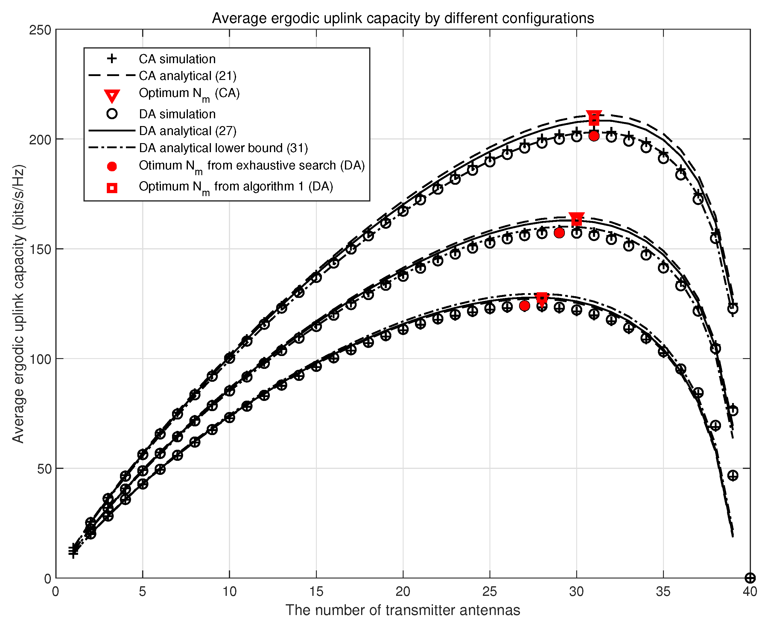
Figure 3 demonstrates the correlation between the mean value of cell capacity and number of transmitting antennas for systems employing CA and DA layouts with
m. We did not use any of the following approximations in our simulations: the high SNR approximation (
16) or the asymptotic orthogonal approximation (
13). The UAV at higher attitude means a stronger direct path, but the lower the diversity gain. Thus the capacity is lower with the bigger
. However, with these two approximations, we obtained analytical results from (
21), (
27), and (
31). For each system configuration, the simulation outcomes and the analytical results agree very well, particularly when
M is small. As the value of
M increases, the signal-to-noise ratio of each antenna decreases. This statement implies that the theoretical results reflect the lower bound of simulation results due to the high SNR approximation. It is very important that we conclude from the data outcomes that the mean value of cell capacity of all systems is concave. As conjectured in Proposition 1, the value of
is slightly lower than that of
, and the lower bound of
is used as a comparison with that of
, which is quite tight. The most desirable value for both DA and CA systems is 30, which is obtained via Algorithm 1; however, the best value for the DA system via exhaustive search is 29 with
. The existing solution is usually to install a single antenna on the train. As shown in
Figure 3, the optimal number of antennas scheme provides a much higher capacity than the single antenna scheme.
In
Figure 4,
indicates the attenuation of RF chain power. The mean value of cell capacity at different
is illustrated in the figure. `X’ marks the optimal operating point. For the DA system, the exhaustive search and Algorithm 1 are the sources of the optimal value of
M. If the power attenuation in the RF chain is greater, both the most advantageous value
M and the mean value cell capacity become smaller. When the most advantageous values of
M = 36,
M = 30, and
M = 25 for co-located antenna and distributed antenna layouts, with
,
, and
.
In
Figure 5, the ergodicity performance at a specific cellular location is depicted as a function of the train’s coordinate. We evaluated all system configurations using (
16) to obtain the analysis results. CAs have different ergodic capacities in different environments. One is strong when in the center of the cell, and the other one is strong when it is far away from BS. The DA has a property that is important for providing stable quality of service throughout the cell. CA and DA layouts show smaller ergodic capacity fluctuations at unique cell locations. Increasing the length of a train reduces its top ergodic capacity but also produces less fluctuation in ergodic capacity.
In
Figure 6, the effect of the UAV altitude on the channel capacity is depicted for the same antenna layout and number of antennas. We have taken
= 100, 200, and 300, respectively, at this point where
= 0.5 and
L = 200. As
becomes larger, the path loss decreases because the sum of the squares of distance
and height
becomes larger, resulting in both the direct and reflected paths becoming easier. As a result, the value of probability of LoS increases because direct paths are more likely to exist. As a result, the path loss dB decreases because more signals can reach the receiver directly. As a result, the cell radius increases because the signal strength can still exceed the signal threshold at greater distances. Additionally, it is easy to see that the average ergodic up-link capacity is smaller when
is larger.
Table 3 shows the optimal antenna number comparison for CA and DA layouts for different
K factors, with
. Furthermore, it provides the benefits of the two layouts.


