Article

Development of a Robot for Decontamination of High Places and Decommissioning Work That Can Cope with Slopes and Steps

National Institute of Technology, Asahikawa College, Asahikawa 071-8142, Japan
*
Author to whom correspondence should be addressed.
Electronics 2023, 12(11), 2403; https://doi.org/10.3390/electronics12112403
Submission received: 31 March 2023 / Revised: 6 May 2023 / Accepted: 12 May 2023 / Published: 25 May 2023

Abstract

:
In this study, a robot was created to compete in the “7th Decommissioning Creative Robot Contest. The “Decommissioning Creative Robot Contest” is a robot contest in which the fields and tasks are set based on the assumption of decommissioning work at TEPCO’s Fukushima Daiichi Nuclear Power Station. The theme of this year’s competition is 3D decontamination of a highly contaminated area inside a nuclear reactor building. To solve the competition problem, we propose a robot for decommissioning work equipped with “an undercarriage mechanism that can cope with slopes and steps”, “a decontamination mechanism with two types of rotation trajectories”, and “a lifting mechanism with a high deformation rate. The undercarriage mechanism uses a four-wheel drive with infinite orbit to cope with slopes and steps. The decontamination mechanism uses two different types of orbits for decontamination: a circular rotating orbit and a longitudinal rotating orbit for rotation. For the lifting mechanism, three pantograph mechanisms were used. This study realized a control and mechanism to overcome steps and slopes, a deployment mechanism to high places, and a mechanism with two types of orbits to carefully decontaminate a large area.

1. Introduction

In this research, a robot was created to compete in the “7th Decommissioning Creative Robot Contest. The “Decommissioning Creative Robot Contest” is a robot contest in which fields and tasks are set based on the assumption of decommissioning work at TEPCO’s Fukushima Daiichi Nuclear Power Station. The objective of the contest is to generate interest in decommissioning among the generation of students who are expected to play an active role in the future, as well as to foster creativity, problem-solving skills, and problem-finding abilities among students. The task of the 7th competition is the three-dimensional decontamination of a highly contaminated area in a nuclear reactor building (decontamination of a high position) as the subject of the competition. Robot development is required to consider issues and solutions and reflect them on the assumption of decommissioning work at TEPCO’s Fukushima Daiichi NPP, which is expected to last a long time. The competition field assumes an actual site, with a 2.7-m-high wall to be decontaminated at the end of a support pole where cables interfere with each other. The target task to be achieved by the robot developed in this research is the three-dimensional decontamination of a highly contaminated area in a nuclear reactor building (decontamination of a high position). The background of this competition is the Great East Japan Earthquake that occurred on 14 March 2011 and the subsequent accident at the Tokyo Electric Power Company, Incorporated Fukushima Daiichi Nuclear Power Station. The accident at the Fukushima Daiichi Nuclear Power Plant affected energy policies not only in the surrounding areas but also in countries around the world that were using nuclear power at the time, and some countries have shifted to energy policies that do not rely on nuclear power [1]. Nuclear power is one of the power generation methods that have various advantages such as a stable fuel supply, no carbon dioxide emissions during power generation, and stable electricity prices. Energy consumption is increasing with population and affluence in modern society, and it is important to consider energy production methods that take biodiversity and the natural environment into account. For this purpose, it is important to use power generation methods that do not emit carbon dioxide, such as nuclear power generation, instead of relying on resources such as coal, oil, and gas [2]. In the current world situation, European countries that have been dependent on natural gas from neighboring countries are reviewing their energy policies and returning to nuclear specifications. [3]. The demand for nuclear power is increasing due to the current situation described above, and technology and human resource development related to decommissioning is extremely important to ensure the safety of nuclear power generation. As for the status of decommissioning of the Fukushima Daiichi Nuclear Power Plant, preparations are underway to isolate groundwater flow from contaminated water leaking from the containment vessel by using a freezing wall, dilute treated tritium water and discharge it into seawater, and remove fuel debris using robot technology [4]. Since various operations are carried out inside the reactor building to remove the debris, it is essential to improve the environment through decontamination, concealment, and removal of radiation sources to reduce radiation levels [5]. In a high-radiation environment such as the inside of a nuclear reactor building, it is dangerous for people to work directly, and because of this limitation, the development of remote-control devices and robots for surveying and decontaminating the inside of nuclear reactor buildings is underway [6,7,8,9,10,11]. In addition, training for operating these remotely operated devices and remotely operated robots and the development of technologies to improve their operability are also underway [12]. In particular, the operation and development of decontamination robots for use at the Fukushima Daiichi Nuclear Power Plant was conducted immediately after the accident. In the development process, some existing remotely operated robots were tested after the accident, and new robots were designed, developed, and operated based on the findings from these tests [13]. Thus, although robotic systems are currently being developed for decommissioning work, the development of robotic systems has so far had a very limited practical application, with challenges that include serious technical difficulties and a lack of testing possibilities for such scenarios. However, there is an advantage that several challenges and scenarios can be addressed and examined through robot competitions, such as the Decommissioning Creation Robot Contest in which the robots developed in this study participate [14]. The purpose of this study is to develop a robot that can solve the tasks of the 7th Decommissioning Creation Robot Contest, which are decontamination of high places in the decommissioning building of the Fukushima Daiichi Nuclear Power Plant and an environment with slopes and steps, to accumulate knowledge about decommissioning and to develop creativity, problem-solving skills, and problem-finding skills.

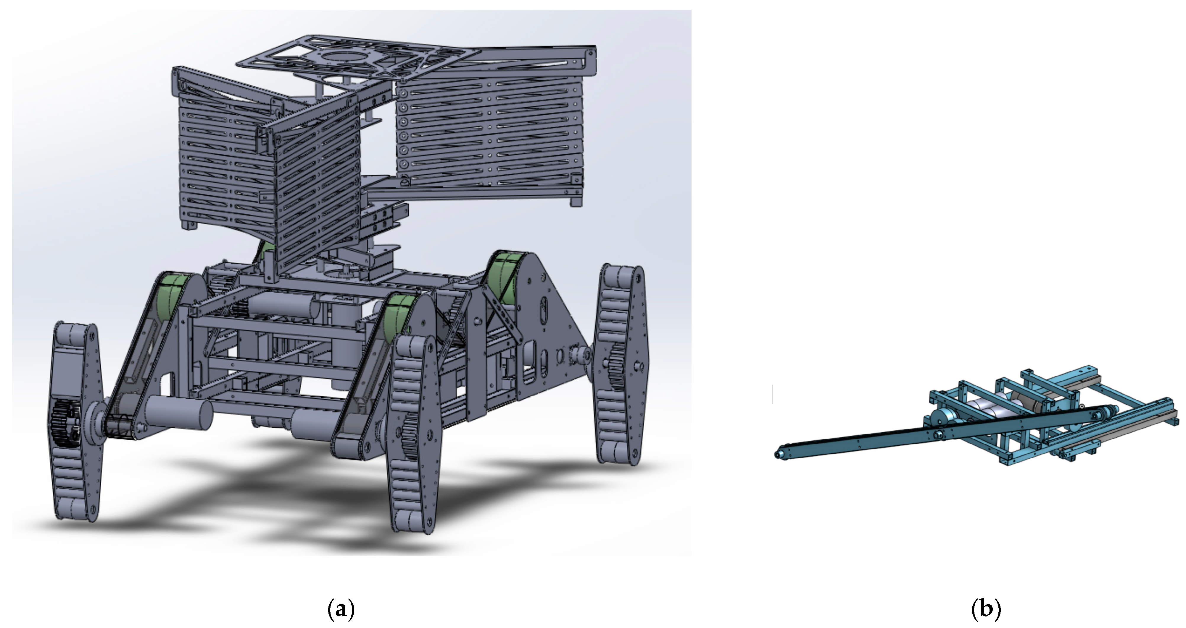
2. Robot System Configuration

2.1. Robot Development Process

The development process of the robot created in this study is shown in Figure 1, in the following order: idea sheet, CAD design, creation, test operation, competition, and redevelopment. In order to enter the 7th Decommissioning Creation Robot Contest, in which we participated in this study, it was necessary to submit an idea sheet as stipulated in the contest rules. The idea sheet describes the concept of the robot and how to solve the problem. The development concept of the robot defined by this development team is “smooth overcoming of steps”, “high deployment rate of the mechanism to reach high places”, and “careful and efficient decontamination”. The features of the mechanisms and controls used to solve the problems are described using figures. The second development process, CAD design, used the 3D CAD design tools SolidWorks and Onshape. Figure 2 shows a 3D CAD model of the robot developed in this study created with SolidWorks and a diagram of the decontamination mechanism created with Onshape. Two different design tools were used in this study because the robot was designed by multiple people: SlidWorks requires a license and requires the use of a specific computer, while Onshape is a free CAD tool that can be used online, making it possible for multiple people to edit the design and use it on multiple terminals. The third development process, the creation of the robot body, involved the use of a metal cutting saw, a tabletop drilling machine, a laser cutting machine, a 3D printer, a milling machine, and a lathe. The main frame of the robot developed in this study was made of aluminum square materials machined by a drilling machine and metal cutting saw, and duralumin plates machined by a laser cutting machine. The pulley for the belt used in the undercarriage mechanism and decontamination mechanism and the pen holding parts used in the decontamination mechanism were created using Acrylonitrile butadiene strene (ABS resin), which is one of the filament materials used in 3D printers. The fourth development process, “test operation”, confirms the operation of each mechanism of the robot created in this study. The final test run is conducted on the day before and the day of the contest in which the robot participates in this study to confirm the operation and safety of the robot, including communication, at the contest site. In the test operation, as a safety measure for the robot, we experimented with several people holding a string to physically stop the robot in case of a runaway in the operation check of the undercarriage mechanism. In the operation test of the deployment mechanism, a person holding a long stick was placed next to the robot in case the robot collapsed because the height of the robot after deployment would be high and unstable. In the fifth development process, “redevelopment”, based on the results of the competition, development was carried out for defects and functions that could not be realized by the competition date.

2.2. Robot Functions

The task to be accomplished by the robot created in this study is to “overcome slopes and steps and decontaminate high places. To accomplish this task, the robot developed in this study has three main mechanisms. The first mechanism is the undercarriage mechanism for overcoming slopes and steps, the second mechanism is the elevation mechanism for deploying the robot to high places, and the third mechanism is the decontamination mechanism for decontaminating the decontamination area.
The undercarriage mechanism consists of a crawler mechanism for the unstable site inside the decommissioned reactor and a mechanism that rotates the crawler mechanism to lift the robot body to overcome the slope and steps. Figure 3 shows the undercarriage mechanism viewed from the side, and Figure 4 shows the angle adjustment unit of the undercarriage mechanism. As shown in Figure 5, to overcome a slope, the angle of the unit in contact with the ground corresponds to the angle of the slope, and to overcome a step, the angle of the unit in contact with the ground is adjusted with respect to the step and the fuselage is lifted to overcome the step.
The elevating mechanism is responsible for raising the decontamination mechanism to a higher position. The elevation mechanism consists of a pantograph mechanism, as shown in Figure 6, combined with three units, as shown in Figure 7. When the robot climbs over a slope or a step, the height of the elevating mechanism is low. When the robot reaches the decontamination area, the elevating mechanism is used to bring the decontamination mechanism to a higher level. By using the lifting mechanism, the decontamination mechanism reaches a height of approximately 3200 mm. To reduce the impossibility due to the weight of the decontamination mechanism installed above the deployment mechanism when the elevating mechanism is deployed, we used multiple auxiliary springs, as shown in Figure 6. The entire mechanism of the lifting mechanism for operating the three pantograph mechanisms, as shown in Figure 7, is shown in Figure 8. A motor placed in the center transmits the power to rise using rack gears connected to each pantograph mechanism.
The decontamination mechanism is used to decontaminate the decontamination area. Current decontamination technologies in decommissioned reactor buildings include high-pressure water jet cleaning equipment, dry ice blast decontamination equipment, and buoy thrust and suction recovery decontamination equipment [5,14]. The robot developed in this study fills in high decontamination areas with a pen as a substitute for decontamination equipment in a competition task. The decontamination mechanism is shown in Figure 9. The decontamination mechanism consists of a rotation mechanism to decontaminate a wide area and a vertical rotation mechanism to paint the edges left unpainted by the rotation mechanism in order to paint the decontamination area efficiently. Figure 10 shows how the decontamination area is painted. As shown in Figure 10, the decontamination area is increased by moving horizontally across the decontamination area while rotating the decontamination mechanism. A large area in the center is decontaminated by the circular rotation orbit, and areas that are difficult to decontaminate by the circular rotation orbit, such as the edges of the decontamination area, are decontaminated by the vertical rotation orbit.

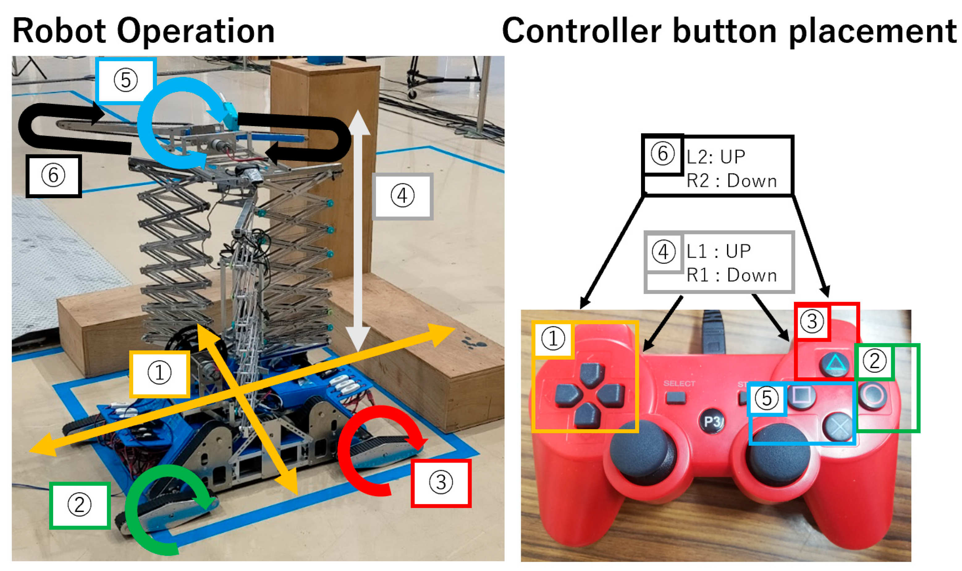
2.3. Electrical Circuits and Control Systems

The robot created in this study uses six motors for the undercarriage mechanism, two for the decontamination mechanism, two for the decontamination mechanism, and one for code management. Figure 11 shows the electrical circuit diagram around the motors of the robot. To use the motors six motor drivers are used that can run two motors. The motors used in the undercarriage mechanism to adjust the angle of the fuselage use four encoders, one for each unit, to control the angle. Raspberry Pi1 operates the drive, elevation, and decontamination mechanisms; Raspberry Pi2 controls the robot’s attitude. This machine uses the GPIO pins of the Raspberry Pi for all signals. During the development phase, the power supplied to the motor drivers was output from the GPIO, and since many motors were used, the signal voltage was insufficient, and the operation was not stable. The problem of insufficient voltage in operation was solved by applying 11.1 V to the control power supply of the motor driver circuit.
When debugging the programming using Raspberry Pi, the robot was connected to a desktop PC with a LAN cable, and SSH communication was used. When actually operating the robot, signals sent to the PC were sent to the Raspberry Pi via serial communication. Four cameras are used to check the surroundings when operating the robot. Figure 12 shows the images acquired by the four cameras. The cameras are used to check the front of the robot, the rear of the robot, the lifting mechanism, and the decontamination by the decontamination mechanism, respectively.
Figure 13 shows a connection diagram of the control system for the robot created in this study. The motor, encoder, and camera used were controlled using three Raspberry Pi units. The Raspberry Pi used was for adjusting the angle of the undercarriage, controlling the motors for the elevation and decontamination mechanism, and acquiring images from the camera, respectively. The motors for adjusting the angle of the undercarriage mechanism were controlled by PID control to control the attitude of the robot; the control quantity for PID control is the rotation angle of the motor for adjusting the angle for controlling the attitude of the robot; Figure 14 shows the control procedure for the simplified PID control. A home-use game controller, as shown in Figure 15, was used to control the robot. The reason for using a home-use game controller is that the controller is familiar to the operator, so the robot can be controlled smoothly and is easily accessible. The robot in this study was operated in five main areas: forward/backward movement, forward angle adjustment, backward angle adjustment, elevation movement, decontamination of a circular rotating orbit, and decontamination of a vertical rotating orbit. Of the numbers shown in Figure 15, number 1 corresponds to the back-and-forth movement, numbers 2 and 3 to the posture adjustment of the robot, number 4 to the vertical movement of the elevator, number 5 to the circular rotation orbit of the decontamination mechanism, and number 6 to the vertical rotation mechanism of the decontamination mechanism. The cable take-up mechanism was installed at the rear of the robot but was not used on the day of the competition because it was not adjusted in time.

2.4. Robot Performance and Comparison with Existing Similar Robots

Table 1 shows the features of the robot fabricated in this study. The elements that are important for a hydraulic cleaning type decontamination robot are water resistance to withstand water work and robustness to withstand high-pressure water splashes, and it is important to utilize existing equipment as much as possible in terms of development efficiency and reliability. The water resistance of the robot fabricated in this study was not considered because it was not included in the requirements for the competition. The decontamination robots actually used at the Fukushima Daiichi Nuclear Power Plant so far have various characteristics. The suction and blast decontamination system (MEISTeR) developed by Mitsubishi Heavy Industries, Ltd, in Tokyo, Japan. is capable of decontaminating by shot blasting and collecting dust that needs to be collected by a collection system and has proven effective in decontaminating floor surfaces in demonstration tests. The same is true for the high-pressure water rinsing system and the dry ice blast decontamination system, which have been shown to be capable of decontamination in demonstration tests. For the development of decontamination equipment for high places, an elevating work platform that uses a pantograph mechanism, which has a proven track record in general industry, is being considered for the high-place deployment mechanism used for dry ice blasting. For robustness, the pantograph mechanism used in the lifting mechanism to access high places was designed based on the concept of using three pantograph mechanisms to cope with shaking after the lifting mechanism is deployed instead of using a structure similar to the conventionally used lifting work platform with two pantograph mechanisms in a pair. The concept was designed to cope with the shaking after the deployment of the lifting mechanism by using three pantograph mechanisms. For the decontamination mechanism, we have improved the decontamination using a circular rotating orbit, which was capable of decontaminating a wide area in the 6th Decommissioning Robot Contest in 2021, and added a longitudinal rotating orbit to address the problem of the four corners of the decontamination area that was a problem in the previous year.

3. Results

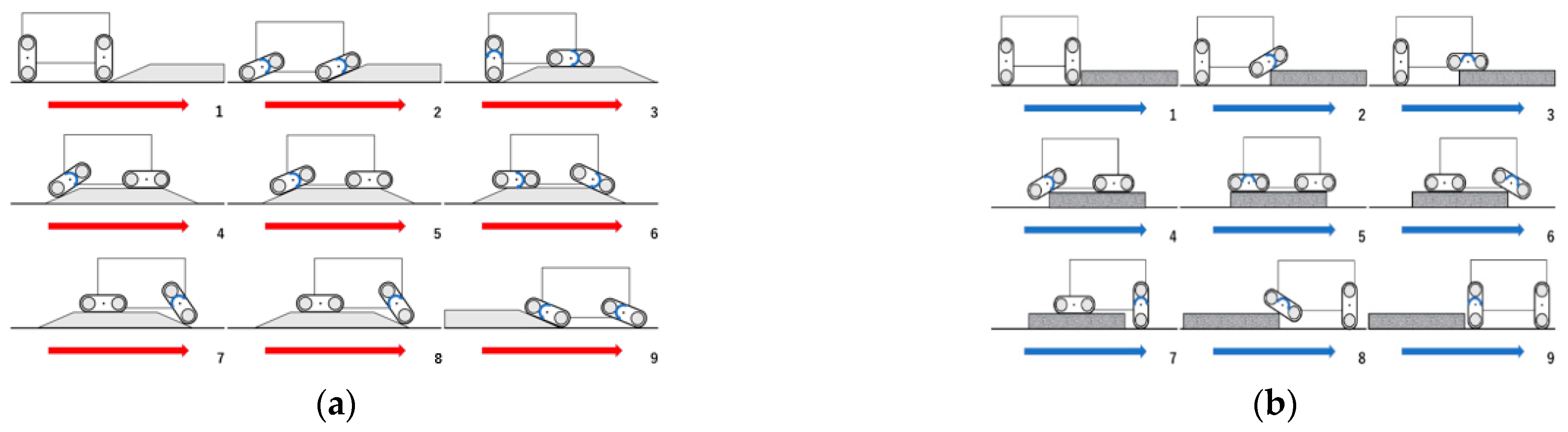
3.1. Overcoming Hills and Steps

A robot created in this study participated in the 7th Decommissioning Creative Robot Contest held on 10 December 2022, at the Narahaa Remote Technology Development Center of the Japan Atomic Energy Agency. In the competition, the robot was unable to accomplish the competition tasks due to a malfunction in the robot’s control system, as shown in Figure 16. Therefore, a demonstration was conducted in the second half of the competition. Figure 17 shows the demonstration conducted in the second half of the competition. In the demonstration, the robot demonstrated the operation of the deployment mechanism and the decontamination mechanism. During the test run on the previous day, the pulley used in the undercarriage mechanism was damaged, so it was not possible to perform the expected operation in the main event. The orange pulley in the middle of the undercarriage mechanism in Figure 18 is the location of the damaged pulley. The damaged pulley is responsible for transmitting drive power to the belts of the front and rear attitude control units, and two pulleys are installed for moving the belts on the left and right sides. As for the decontamination mechanism, the planned decontamination mechanism with two different rotations was not completed by the day of the competition, so it was rebuilt and reexamined after the competition.
A crawler-based undercarriage mechanism with four robot attitude control units was created to overcome steps and hills. To control the attitude of the robot, the angle of rotation of the motor was read by an encoder, and the read value was fed back by PID control to adjust the angle of the motor to the target angle. There are two external forces that affect the attitude control of the robot in the undercarriage mechanism: the first is the weight of the robot itself, and the second is the force of the angle adjustment unit rotating when the moving belt is in motion. In order to confirm that the above two external forces can be suppressed by PID control and that the robot’s posture can be controlled, motion experiments were conducted for each of these external forces.
The first experiment was to suppress the effect of the robot’s own weight. Figure 19 shows the robot in motion before angle adjustment by PID control. The robot’s posture is not stable due to its own weight and cannot be kept in a constant posture. Figure 20 shows the result of the robot’s movement after angle control by PID control.
The second movement experiment is to control the rotation of the angle adjustment unit, which occurs simultaneously with the movement of the belt for movement. When the rotation of the angle adjustment unit is not controlled, the four angle adjustment units rotate simultaneously with the movement of the moving belt, as shown in Figure 21. By controlling the rotation of the angle adjustment units, the angle of the angle adjustment units can be kept constant while the moving belt moves, as shown in Figure 22.

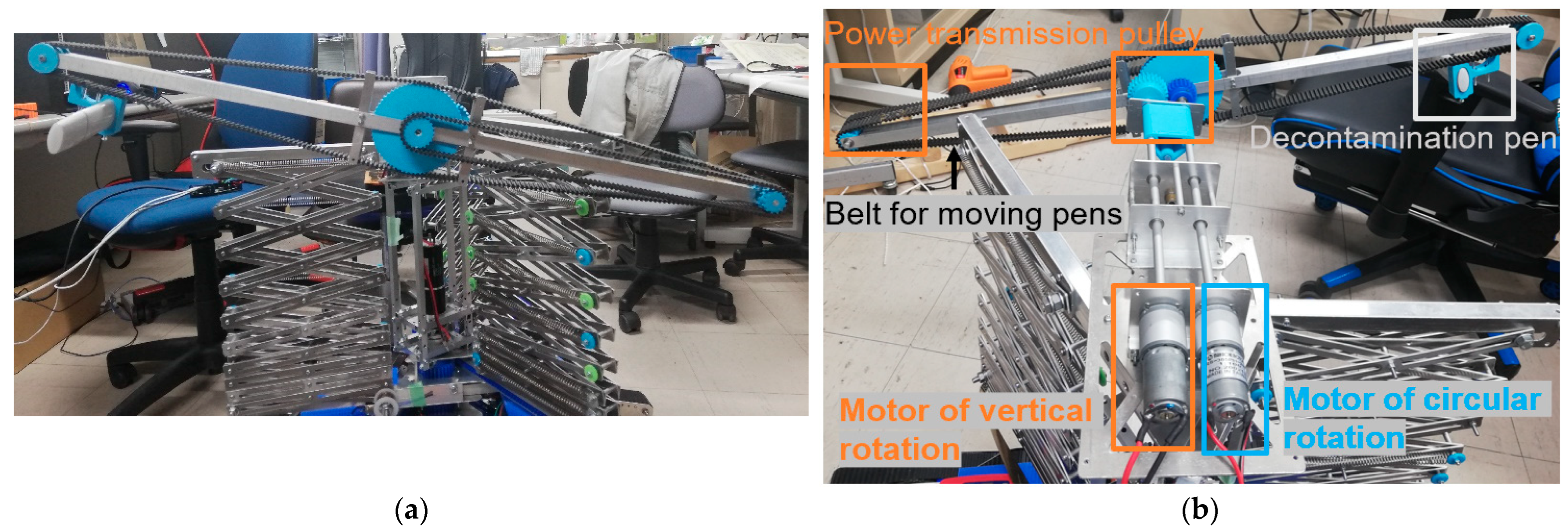
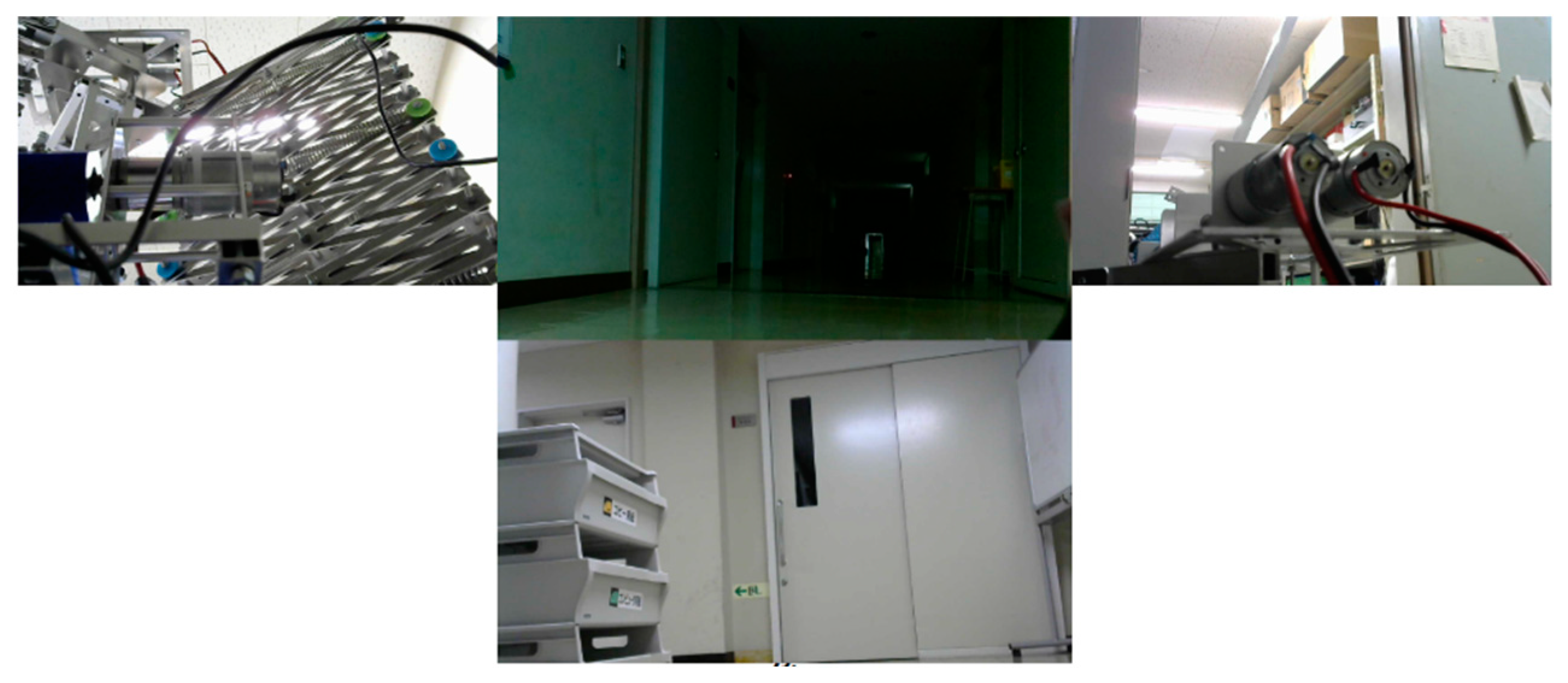
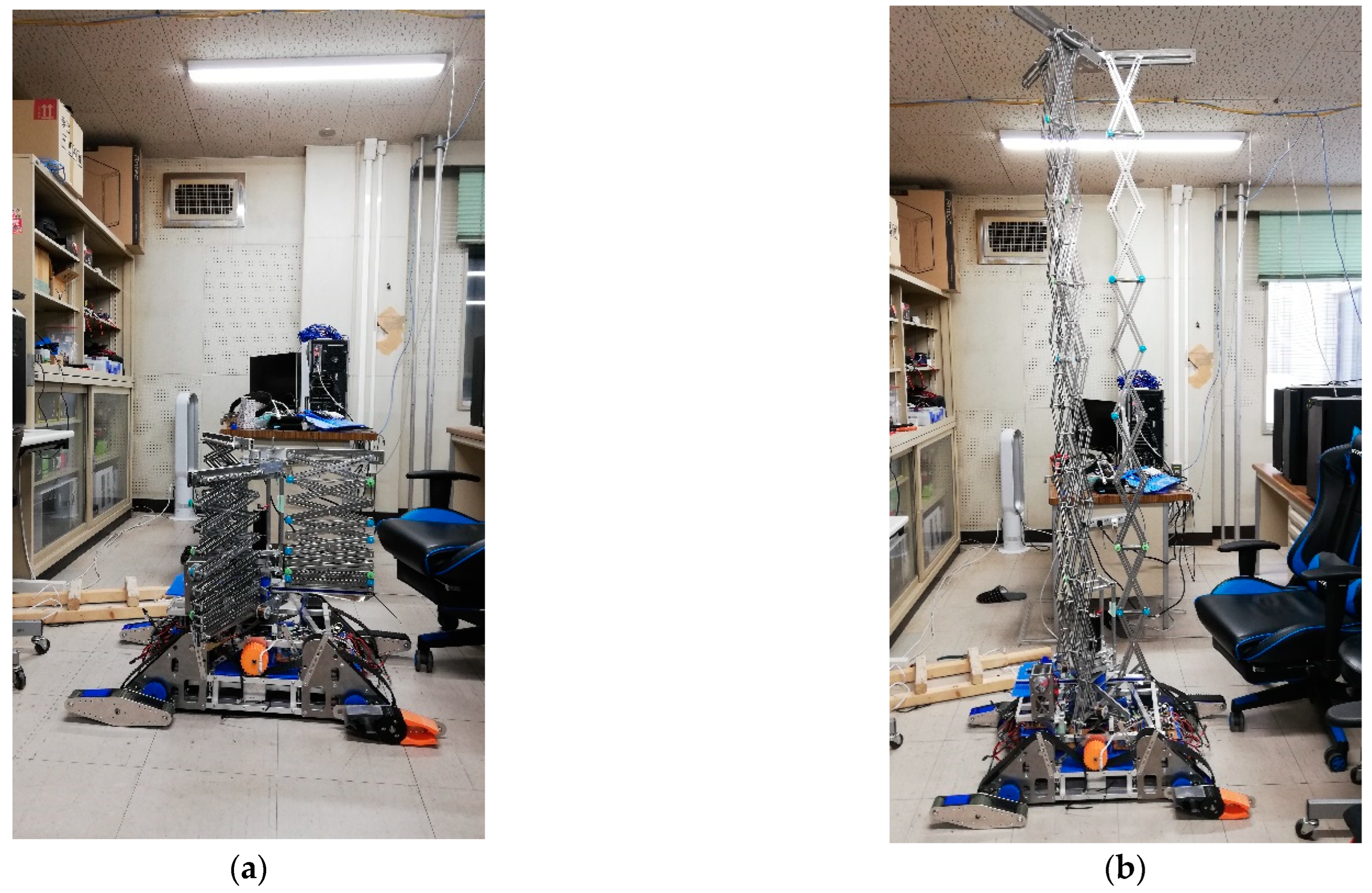
3.2. Deployment to High Altitudes

The created deployment mechanism is shown in Figure 23; the elevation mechanism was created by combining three pantograph mechanisms. The height of the elevating mechanism before deployment is about 800 mm, and the height after deployment is about 3200 mm. Since the decontamination mechanism is installed at the top of the elevating mechanism, a constant load spring and a pull spring are used to support the pantograph mechanism. The three pantograph mechanisms are powered by gears and rack gears directly connected to two motors located in the center of the elevating mechanism.

3.3. Results of Decontamination Mechanism Operation

Since the originally planned decontamination mechanism with two types of rotational orbits was not completed for implementation on the robot on the day of the competition, the robot participated in the competition with a decontamination mechanism for circular rotational orbits only. After the competition, a mechanism for a vertical rotation orbit was added to realize the two types of rotation orbits in the development concept. There were two reasons for not being able to implement vertical rotation before the competition. The first was that the belt used to transmit power for vertical rotation was a single belt, which was spinning, and the second was the heavy weight of the decontamination mechanism. To solve these two causes, two belts were used to transmit power for vertical rotation, and to reduce weight, the material used for the rotating shaft was changed from iron material to aluminum material.
The decontamination mechanism realized by the post-convention improvements uses two types of rotating orbits for decontamination. Figure 24 shows decontamination using a circular rotating orbit, and Figure 25 shows decontamination using a vertical rotating orbit. Figure 26 shows the results of decontamination using the circular orbit. Figure 27 shows the results of decontamination using the circular and vertical rotation orbits. Figure 27 shows that the vertical rotary orbit can cover the four corners of the decontamination area that could not be decontaminated by the circular rotary orbit.

4. Discussion

4.1. Evaluation of the Undercarriage Mechanism

Two motion experiments confirmed that the undercarriage mechanism created in this study can perform the movements necessary to overcome hills and steps. On the other hand, we confirmed that the pulley that transfers the drive power to the belt was damaged when the machine was turning. This was because the pulley was created using a 3D printer and was made of ABS material. In actual decontamination work of decommissioned nuclear reactors, the undercarriage mechanism, which is necessary for robot movement, is a particularly important component of the robot. Therefore, parts that are subject to loads, such as transmitting driving power, must be made of high-strength materials. By solving the problem of the strength of these components, a more stable undercarriage mechanism can be realized.

4.2. Evaluation of Deployment Mechanisms

The objective of this study was to develop a robot with functions to overcome steps and slopes and to decontaminate high places, which are necessary for the decontamination of decommissioned nuclear reactors. We realized a control and mechanism to overcome steps and slopes, a mechanism to deploy to high places, and a mechanism with two types of activation to carefully decontaminate a wide area. From the discussion based on the results, it is necessary to increase the strength of the load-bearing parts in order for the undercarriage mechanism to operate stably. Since the undercarriage mechanism in this study had problems with the strength of pulleys created by a 3D printer, metal parts should be prioritized for use in actual applications rather than prototypes. In the deployment mechanism, a lightweight mechanism such as the decontamination mechanism used in this study can be raised, but it is necessary to devise a power transmission method when the weight to be raised increases. Regarding the stability of the deployment mechanism, although there was a decrease in stability due to the increase in the number of parts used in the pantograph mechanism, the use of three pantographs can accommodate changes in the center of gravity due to the deployment of the decontamination mechanism, and an increase in stability can be expected by increasing the number of connection points for each of the three pantographs. The stability is expected to be increased by increasing the number of connection points for each of the three pantographs. In the decontamination mechanism, the four corner areas of the rectangular decontamination area could be painted by using an additional longitudinal rotational track rather than only a circular rotational track. Of the two types of decontamination orbits, it was found necessary to improve the fixing method of the decontamination end-effector for the longitudinal rotational orbit to be stronger and more stable than the method of fixing the end-effector directly to the power transmission belt. The robot created in this research participated in the 7th Decommissioning Creation Robot Contest and failed to operate as expected due to malfunctions in the undercarriage and communication system. By solving these problems, it will be possible to realize and operate a decontamination robot that can help solve the problem of decontamination work at high places, which has become an issue in decommissioning work.

Author Contributions

Conceptualization, S.O., Y.Y., S.K., S.M. and N.I.; methodology, S.O., Y.Y., S.K., K.I., K.K. and S.M.; software, Y.Y. and K.I.; writing—original draft preparation, S.O. and N.I.; writing—review and editing, S.O., T.S. and N.I.; supervision, K.K., S.M., T.S. and N.I.; project administration, N.I. All authors have read and agreed to the published version of the manuscript.

Funding

This research received no external funding.

Institutional Review Board Statement

Not applicable.

Informed Consent Statement

Not applicable.

Conflicts of Interest

The authors declare no conflict of interest.

References

  1. Wittneben, B.B.F. The impact of the Fukushima nuclear accident on European energy policy. Environ. Sci. Policy 2012, 15, 1–3. [Google Scholar] [CrossRef]
  2. Brook, B.W.; Bradshaw, C.J.A. Key role for nuclear energy in global biodiversity conservation. Conserv. Biol. 2014, 29, 702–712. [Google Scholar] [CrossRef] [PubMed]
  3. Osička, J.; Černoch, F. European energy politics after Ukraine: The road ahead. Energy Res. Soc. Sci. 2022, 91, 102757. [Google Scholar] [CrossRef]
  4. Narabayashi, T. Fukushima Daiichi nuclear power plant accident and analysis evaluation, Boiling Water Reactors. In JSME Series in Thermal and Nuclear Power Generation; Elsevier: Amsterdam, The Netherlands, 2023; Volume 4, pp. 335–406. [Google Scholar]
  5. Tetsuo, K. Robot challenges for nuclear decommissioning of Fukushima Daiichi Power Station. In Proceedings of the International Conference on Advancing the Global Implementation of Decommissioning and Environmental Remediation Programmes, Madrid, Spain, 23–27 May 2016; International Atomic Energy Agency (IAEA): Vienna, Austria, 2017. [Google Scholar]
  6. Hideaki, O. R&D outline for decommissioning of the Fukushima Daiichi Nuclear Power Station. In Proceedings of the International Conference on Advancing the Global Implementation of Decommissioning and Environmental Remediation Programmes, Madrid, Spain, 23–27 May 2016; International Atomic Energy Agency: Vienna, Austria, 2017. [Google Scholar]
  7. Okada, S.; Hirano, K.; Kobayashi, R.; Kometani, Y. Development and application of robotics for decommissioning of Fukushima Daiichi nuclear power plant. Hitachi Rev. 2020, 69, 556–557. [Google Scholar]
  8. Yamada, T.; Abe, H.; Kawabata, K. Development of Testing Method Considering Tasks with Remotely Controlled Robots in Fukushima Daiichi Nuclear Power Station. In Proceedings of the 2021 IEEE International Conference on Intelligence and Safety for Robotics (ISR), Tokoname, Japan, 4–6 March 2021; pp. 131–134. [Google Scholar]
  9. Asama, H. Plenary talk III: Robot & remote-controlled machine technology for response of disasters and accidents of nuclear power plants. In Proceedings of the 2012 Proceedings of SICE Annual Conference (SICE), Akita, Japan, 20–23 August 2012. [Google Scholar]
  10. Petereit, J.; Beyerer, J.; Asfour, T.; Gentes, S.; Hein, B.; Hanebeck, U.D.; Kirchner, F.; Dillmann, R.; Götting, H.H.; Weiser, M.; et al. ROBDEKON: Robotic Systems for Detain in Danger Environment. In Proceedings of the 2019 IEEE International Symposium on Safety, Security, and Rescue Robotics (SSRR), Wurzburg, Germany, 2–4 September 2019; pp. 249–255. [Google Scholar]
  11. Michal, V. Remote operation and robotics technologies in nuclear decommissioning projects. In Nuclear Decommissioning; Woodhead Publishing Series in Energy; Elsevier: Amsterdam, The Netherlands, 2012; pp. 346–374. [Google Scholar]
  12. Kawabata, K.; Suzuki, K. Development of a Robot Simulator for Remote Operations for Nuclear Decommissioning. In Proceedings of the 2019 16th International Conference on Ubiquitous Robots (UR), Jeju, Republic of Korea, 24–27 June 2019; pp. 501–504. [Google Scholar]
  13. Yokokohji, Y. The Use of Robots to Respond to Nuclear Accidents: Applying the Lessons of the Past to the Fukushima Daiichi Nuclear Power Station. Annu. Rev. Control Robot. Auton. Syst. 2021, 4, 681–710. [Google Scholar] [CrossRef]
  14. Schneider, F.E.; Wildermuth, D. Real-World Robotic Competitions for Radiological and Nuclear Inspection Tasks. In Proceedings of the 2019 20th International Carpathian Control Conference (ICCC), Kraków, Poland, 26–29 May 2019; pp. 1–6. [Google Scholar]
Figure 1. Transition diagram of the development process.
Electronics 12 02403 g001
Figure 2. Overall view of the created robot: (a) CAD design of robots; (b) Robot created based on CAD design.
Electronics 12 02403 g002
Figure 3. Undercarriage mechanism viewed from the side.
Electronics 12 02403 g003
Figure 4. Unit for angle adjustment of undercarriage mechanism: (a) Parts related to belt power transmission; (b) Parts related to gear power transmission.
Electronics 12 02403 g004
Figure 5. Imagery of Overcoming Slopes and Steps: (a) Overcoming a hill; (b) Overcoming Steps.
Electronics 12 02403 g005
Figure 6. Operating Principle of Pantograph Mechanism for Elevating Mechanism.
Electronics 12 02403 g006
Figure 7. Mechanism deployment viewed from above.
Electronics 12 02403 g007
Figure 8. Central part of deployment mechanism: (a) Three pantograph mechanisms and supporting springs; (b) Location of power transmission components and motors.
Electronics 12 02403 g008
Figure 9. Decontamination mechanism: (a) Decontamination mechanism viewed from the front; (b) Decontamination mechanism viewed from behind at an angle.
Electronics 12 02403 g009
Figure 10. Diagram of decontamination method.
Electronics 12 02403 g010
Figure 11. Electrical circuit connection diagram: (a) Electrical connection diagram of the lifting mechanism and drive; (b) Electrical connection diagram of angle adjustment mechanism.
Electronics 12 02403 g011
Figure 12. Camera image displayed on the robot operator’s control screen.
Electronics 12 02403 g012
Figure 13. Control system connection diagram.
Electronics 12 02403 g013
Figure 14. Control system connection diagram.
Electronics 12 02403 g014
Figure 15. Controllers used for maneuvering.
Electronics 12 02403 g015
Figure 16. Robots in the first half of the competition.
Electronics 12 02403 g016
Figure 17. Demonstration of the second half of the competition.
Electronics 12 02403 g017
Figure 18. Damaged pulleys in the undercarriage mechanism.
Electronics 12 02403 g018
Figure 19. Result of robot operation before PID control.
Electronics 12 02403 g019
Figure 20. Control results to target angle using PID control.
Electronics 12 02403 g020
Figure 21. Results of moving belt operation before using PID control.
Electronics 12 02403 g021
Figure 22. Results of moving belt operation using PID control.
Electronics 12 02403 g022
Figure 23. Deployment of lifting mechanism: (a) Elevation mechanism before deployment; (b) Elevation mechanism after deployment.
Electronics 12 02403 g023
Figure 24. Decontamination by circular rotating orbit of decontamination mechanism.
Electronics 12 02403 g024
Figure 25. Decontamination by vertical rotation orbit of decontamination mechanism.
Electronics 12 02403 g025
Figure 26. Results of decontamination by circular rotational orbit.
Electronics 12 02403 g026
Figure 27. Decontamination results including longitudinal rotation orbit.
Electronics 12 02403 g027
Table 1. Robot mechanisms and features.
ConfigurationFunctions and RolesMechanisms Comprising the FunctionFeature
Undercarriage mechanismRobot movement, overcoming steps and slopesFour crawler mechanisms with adjustable anglesMaintaining and moving posture
Deployment mechanismDeploy decontamination mechanisms at high elevations.Three pantograph mechanismsHigh deployment rate
Decontamination mechanismPaint the decontamination areaTwo types of rotating mechanismsCareful and fast decontamination
Disclaimer/Publisher’s Note: The statements, opinions and data contained in all publications are solely those of the individual author(s) and contributor(s) and not of MDPI and/or the editor(s). MDPI and/or the editor(s) disclaim responsibility for any injury to people or property resulting from any ideas, methods, instructions or products referred to in the content.

