
Ultra-Wideband Graphene-Based Micro-Sized Circular Patch-Shaped Yagi-like MIMO Antenna for Terahertz Wireless Communication


Abstract
:1. Introduction
- Microstrip technology is used to design the graphene-based circular patch-shaped Yagi-like ultra-wideband MIMO antenna. Thus, it is smaller, lighter, easier to build, and more cost effective than other THz antennas.
- The suggested antenna has a substantially broader bandwidth (10.96 THz).
- The proposed MIMO structure offers better diverse performance parameters: DG ≈ 10 dB, CCL < 0.5 bps/Hz/s, TARC ≤ −10.0 dB, MEG ≤ −3.0 dB, and ECC < 0.01). This helps to overcome the challenges associated with short-distance communication such as signal fading, multipath propagation, and increased interference.
2. Graphene-Based Circular Patch-Shaped Yagi-like MIMO Antenna
3. Results and Discussion
4. Conclusions
Author Contributions
Funding
Data Availability Statement
Conflicts of Interest
Appendix A

| Types of Antenna | Types of Antenna | Configuration |
|---|---|---|
| Type 1 | 2 × 2 |  |
| Type 2 | 1 × 2 |  |
| Type 3 | 2 × 1 |  |
| Type 4 | 1 × 1 |  |
| Type 5 | All patch, one side |  |


Appendix B
References
- Cisco: Cisco Visual Networking Index (VNI) Global Mobile Data Traffic Forecast Update, 2017–2022 White Paper. 2019. Available online: https://www.gsma.com/spectrum/wp-content/uploads/2013/03/Cisco_VNI-global-mobile-data-traffic-forecast-update.pdf (accessed on 10 March 2022).
- Ying, Z. Antennas in Cellular Phones for Mobile Communications. Proc. IEEE 2012, 100, 2286–2296. [Google Scholar] [CrossRef]
- Rappaport, T.S.; Sun, S.; Mayzus, R.; Zhao, H.; Azar, Y.; Wang, K.; Wong, G.; Schulz, J.K.; Samimi, M.; Gutierrez, F. Millimeter Wave Mobile Communications for 5G Cellular: It Will Work! IEEE Access 2013, 1, 335–349. [Google Scholar] [CrossRef]
- He, Y.; Chen, Y.; Zhang, L.; Wong, S.-W.; Chen, Z.N. An overview of terahertz antennas. China Commun. 2020, 17, 124–165. [Google Scholar] [CrossRef]
- Singh, R.; Lehr, W.; Sicker, D.; Huq, K.M.S. Beyond 5G: The Role of THz Spectrum. SSRN Electron. J. 2019. [Google Scholar] [CrossRef]
- Formanek, F.; Brun, M.-A.; Umetsu, T.; Omori, S.; Yasuda, A. Aspheric silicon lenses for terahertz photoconductive antennas. Appl. Phys. Lett. 2009, 94, 021113. [Google Scholar] [CrossRef]
- Saurabh, L.; Bhatnagar, A.; Kumar, S. Design and performance analysis of bow-tie photoconductive antenna for THz application. In Proceedings of the 2017 International Conference on Intelligent Computing and Control (I2C2), Coimbatore, India, 23–24 June 2017; Volume 2018, pp. 1–3. [Google Scholar]
- Gonzalez, A.; Kaneko, K.; Kojima, T.; Asayama, S.; Uzawa, Y. Terahertz Corrugated Horns (1.25–1.57 THz): Design, Gaussian Modeling, and Measurements. IEEE Trans. Terahertz Sci. Technol. 2017, 7, 42–52. [Google Scholar]
- Devapriya, A.T.; Robinson, S. Investigation on Metamaterial Antenna for Terahertz Applications. J. Microwaves Optoelectron. Electromagn. Appl. 2019, 18, 377–389. [Google Scholar] [CrossRef]
- Mak, K.-M.; So, K.-K.; Lai, H.-W.; Luk, K.-M. A Magnetoelectric Dipole Leaky-Wave Antenna for Millimeter-Wave Application. IEEE Trans. Antennas Propag. 2017, 65, 6395–6402. [Google Scholar] [CrossRef]
- Khamaisi, B.; Jameson, S.; Socher, E. A 210–227 GHz Transmitter With Integrated On-Chip Antenna in 90 nm CMOS Technology. IEEE Trans. Terahertz Sci. Technol. 2013, 3, 141–150. [Google Scholar] [CrossRef]
- Varshney, G. Tunable Terahertz Dielectric Resonator Antenna. Silicon 2021, 13, 1907–1915. [Google Scholar] [CrossRef]
- Zhou, M.M.; Cheng, Y.J. D-Band High-Gain Circular-Polarized Plate Array Antenna. IEEE Trans. Antennas Propag. 2018, 66, 1280–1287. [Google Scholar] [CrossRef]
- Dhillon, A.S.; Mittal, D.; Sidhu, E. THz rectangular microstrip patch antenna employing polyimide substrate for video rate imaging and homeland defence applications. Optik 2017, 144, 634–641. [Google Scholar] [CrossRef]
- Sirmaci, Y.D.; Akin, C.K.; Sabah, C. Fishnet based metamaterial loaded THz patch antenna. Opt. Quantum Electron. 2016, 48, 168. [Google Scholar] [CrossRef]
- Paul, L.C.; Islam, M. Proposal of wide bandwidth and very miniaturized having dimension of μm range slotted patch THz microstrip antenna using PBG substrate and DGS. In Proceedings of the 20th International Conference of Computer and Information Technology (ICCIT), Dhaka, Bangladesh, 22–24 December 2017; Volume 2018, pp. 1–6. [Google Scholar] [CrossRef]
- Vettikalladi, H.; Sethi, W.; Bin Abas, A.F.; Ko, W.; Alkanhal, M.A.; Himdi, M. Sub-THz Antenna for High-Speed Wireless Communication Systems. Int. J. Antennas Propag. 2019, 2019, 9573647. [Google Scholar] [CrossRef] [Green Version]
- Geim, A. Graphene—The perfect atomic lattice. Uspekhi Fiz. Nauk 2011, 181, 1283. [Google Scholar]
- Patel, S.K.; Sorathiya, V.; Nguyen, T.K.; Dhasarathan, V. Numerical investigation of tunable metasurface of graphene split-ring resonator for terahertz frequency with reflection controlling property. Phys. E Low-Dimens. Syst. Nanostruct. 2019, 118, 113910. [Google Scholar] [CrossRef]
- Anand, S.; Kumar, D.S.; Wu, R.J.; Chavali, M. Graphene nanoribbon based terahertz antenna on polyimide substrate. Optik 2014, 125, 5546–5549. [Google Scholar] [CrossRef]
- Thampy, A.S.; Darak, M.S.; Dhamodharan, S.K. Analysis of graphene based optically transparent patch antenna for terahertz communications. Phys. E Low-Dimens. Syst. Nanostruct. 2015, 66, 67–73. [Google Scholar] [CrossRef]
- Babu, K.V.; Anuradha, B. Design of inverted L-shape & ohm symbol inserted MIMO antenna to reduce the mutual coupling. AEU—Int. J. Electron. Commun. 2019, 105, 42–53. [Google Scholar] [CrossRef]
- Sree, G.N.J.; Nelaturi, S. Design and experimental verification of fractal based MIMO antenna for lower sub 6-GHz 5G applications. AEU—Int. J. Electron. Commun. 2021, 137, 153797. [Google Scholar] [CrossRef]
- Babu, K.V.; Anuradha, B.; Das, S. Design & analysis of a dual-band MIMO antenna to reduce the mutual coupling. J. Instrum. 2019, 14, P09023. [Google Scholar] [CrossRef]
- Nasir, J.; Jamaluddin, M.H.; Khalily, M.; Kamarudin, M.R.; Ullah, I.; Selvaraju, R. A reduced size dual port MIMO DRA with high isolation for 4G applications. Int. J. RF Microw. Comput. Eng. 2015, 25, 495–501. [Google Scholar] [CrossRef] [Green Version]
- Sharawi, M.S. Printed Multi-Band MIMO Antenna Systems and Their Performance Metrics [Wireless Corner]. IEEE Antennas Propag. Mag. 2013, 55, 218–232. [Google Scholar] [CrossRef]
- Azarbar, A.; Masouleh, M.S.; Behbahani, A.K. A new terahertz microstrip rectangular patch array antenna. Int. J. Electromagn. Appl. 2014, 4, 25–29. [Google Scholar]
- Mahmud, R.H. Terahertz Microstrip Patch Antennas For The Surveillance Applications. Kurd. J. Appl. Res. 2020, 5, 16–27. [Google Scholar] [CrossRef]
- Nejati, A.; Sadeghzadeh, R.A.; Geran, F. Effect of photonic crystal and frequency selective surface implementation on gain enhancement in the microstrip patch antenna at terahertz frequency. Phys. B Condens. Matter 2014, 449, 113–120. [Google Scholar] [CrossRef]
- Sharma, A.; Singh, G. Rectangular Microstirp Patch Antenna Design at THz Frequency for Short Distance Wireless Communication Systems. J. Infrared Millim. Terahertz Waves 2008, 30, 1. [Google Scholar] [CrossRef]
- Hocini, A.; Temmar, M.; Khedrouche, D.; Zamani, M. Novel approach for the design and analysis of a terahertz microstrip patch antenna based on photonic crystals. Photonics Nanostruct.-Fundam. Appl. 2019, 36, 100723. [Google Scholar] [CrossRef]
- Kushwaha, R.K.; Karuppanan, P.; Malviya, L. Design and analysis of novel microstrip patch antenna on photonic crystal in THz. Phys. B Condens. Matter 2018, 545, 107–112. [Google Scholar] [CrossRef]
- Younssi, M.; Jaoujal, A.; Yaccoub, M.D.; El Moussaoui, A.; Aknin, N. Study of a Microstrip Antenna with and Without Superstrate for Terahertz Frequency. Int. J. Innov. Appl. Stud. 2013, 2, 369–371. [Google Scholar]
- Jha, K.R.; Singh, G. Dual-band rectangular microstrip patch antenna at terahertz frequency for surveillance system. J. Comput. Electron. 2010, 9, 31–41. [Google Scholar] [CrossRef]
- Krishna, C.M.; Das, S.; Nella, A.; Lakrit, S.; Madhav, B.T.P. A Micro-Sized Rhombus-Shaped THz Antenna for High-Speed Short-Range Wireless Communication Applications. Plasmonics 2021, 16, 2167–2177. [Google Scholar] [CrossRef]
- Sharma, A.; Dwivedi, V.K.; Singh, G. THz rectangular microstrip patch antenna on multilayered substrate for advance wireless communication systems. In Proceedings of the Progress in Electromagnetics Research Symposium, Beijing, China, 23–27 March 2009; Volume 1, pp. 617–621. [Google Scholar]
- Johansson, J.; Whyborn, N. The diagonal horn as a sub-millimeter wave antenna. IEEE Trans. Microw. Theory Tech. 1992, 40, 795–800. [Google Scholar] [CrossRef]
- Chattopadhyay, G.; Alonso-Delpino, M.; Chahat, N.; González-Ovejero, D.; Lee, C.; Reck, T. Terahertz Antennas and Feeds. In Aperture Antennas for Millimeter and Sub-Millimeter Wave Applications; Signals and Communication Technology; Springer: Cham, Switzerland, 2018; pp. 335–386. [Google Scholar] [CrossRef]
- Reck, T.J.; Jung-Kubiak, C.; Gill, J.; Chattopadhyay, G. Measurement of Silicon Micromachined Waveguide Components at 500–750 GHz. IEEE Trans. Terahertz Sci. Technol. 2013, 4, 33–38. [Google Scholar] [CrossRef]
- Krishna, C.M.; Das, S.; Lakrit, S.; Lavadiya, S.; Madhav, B.T.P.; Sorathiya, V. Design and analysis of a super wideband (0.09−30.14 THz) graphene based log periodic dipole array antenna for terahertz applications. Optik 2021, 247, 167991. [Google Scholar] [CrossRef]


| a1 | a2 | a3 | a4 | r1 | r2 | r3 | r4 | h | l | t | g1 | g2 |
|---|---|---|---|---|---|---|---|---|---|---|---|---|
| 50 | 140 | 180 | 180 | 15 | 25 | 35 | 45 | 40 | 350 | 70 | 100 | 350 |
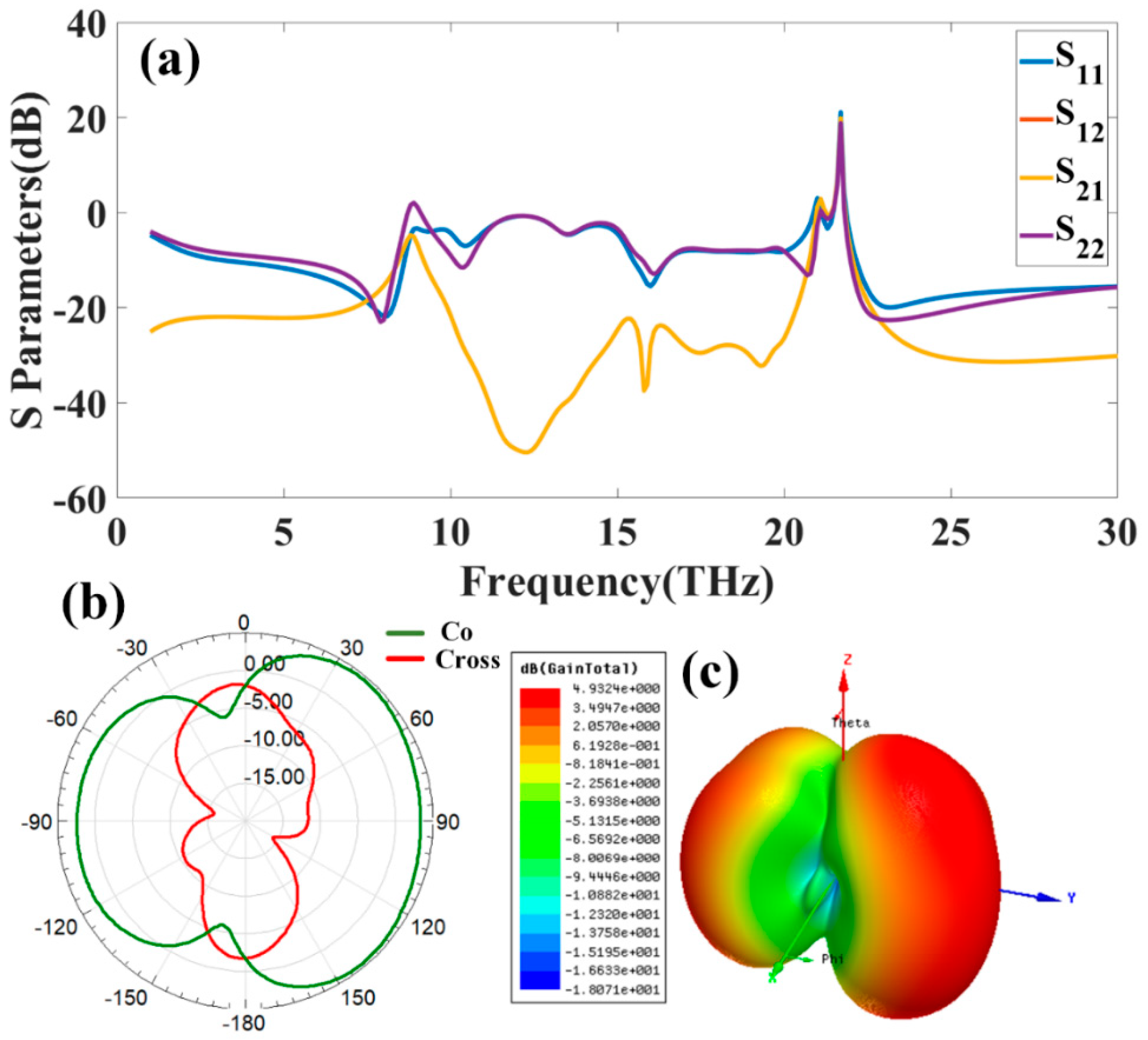
| Port Excitation | Number of Bands | Minimum and Maximum Frequency (THz) | Bandwidth (THz) | Maximum Return Loss (dB) |
|---|---|---|---|---|
| Port 1 | 1 | 3.05–11.01 | 7.96 | −15.31 |
| 2 | 15.85–16.47 | 0.63 | −12.49 | |
| 3 | 19.98–30 | 10.02 | −23.44 | |
| Port 2 | 1 | 2.26–10.04 | 7.78 | −28.67 |
| 2 | 15.63–16.61 | 0.98 | −15.38 | |
| 3 | 18.84–27.96 | 9.12 | −22.55 | |
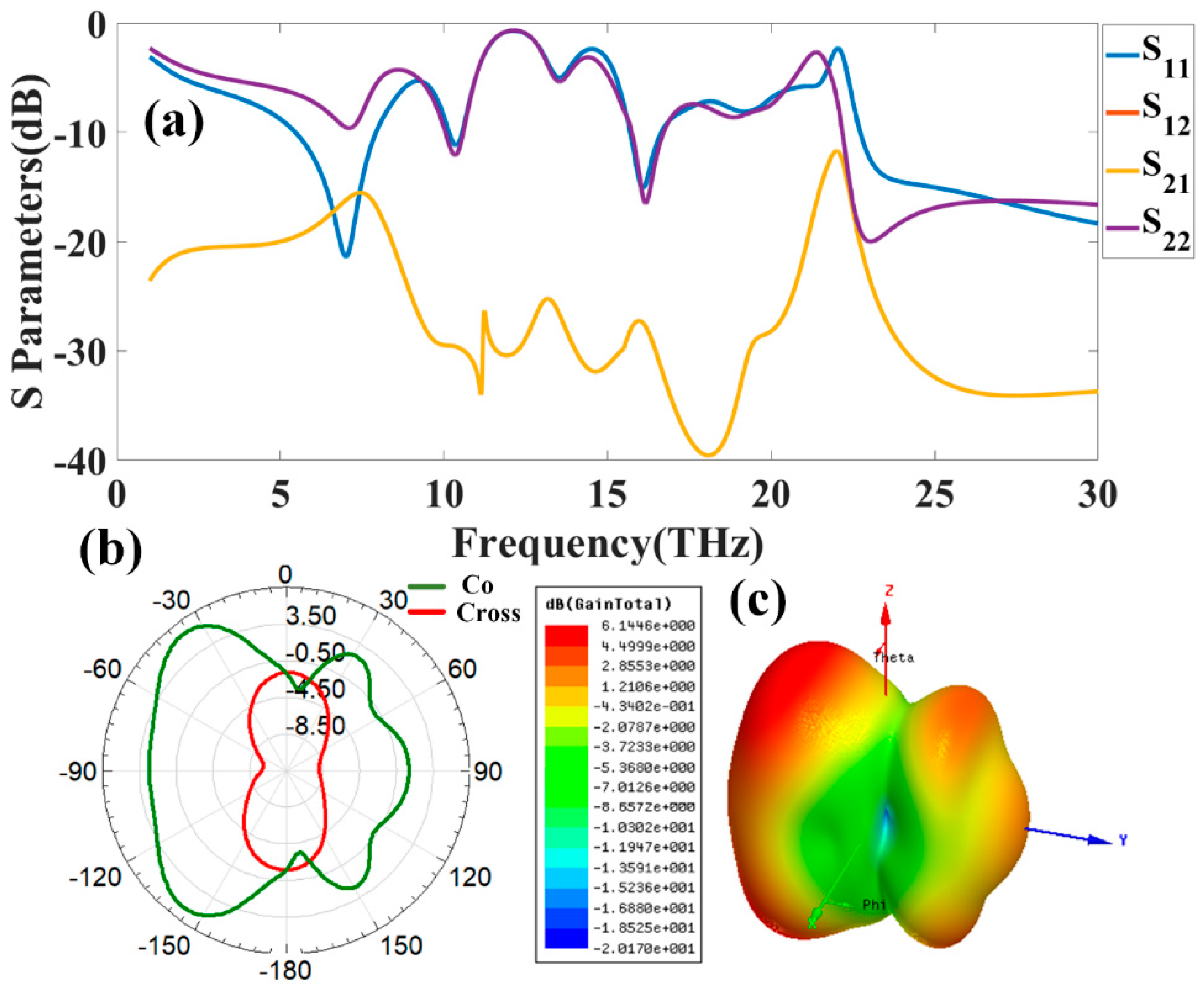
| Port 3 | 1 | 3.51–11.43 | 7.92 | −14.13 |
| 2 | 15.82–16.51 | 0.69 | −13.19 | |
| 3 | 19.14–30 | 10.86 | −26.59 | |
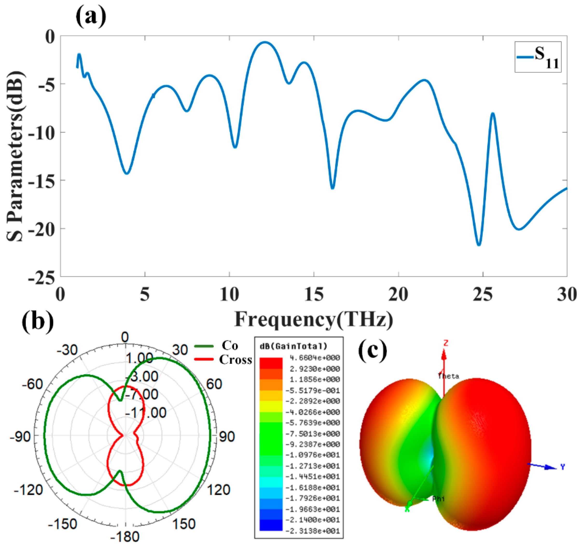
| Port 4 | 1 | 3.68–10.52 | 6.84 | −13.29 |
| 2 | 15.88–16.24 | 0.36 | −11.93 | |
| 3 | 19.04–30 | 10.96 | −18.85 |
| Reference | Substrate | Gain (dB) | Dimension (µm × µm) | Bandwidth (THz) |
|---|---|---|---|---|
| This work | Polyimide | ~7 | (620, 800) | 10.96 |
| [27] | Tetrafluoroethylene | - | (109.76, 150.93) | 0.13 |
| [28] | RT/Duroid 6006 | 9.7 | (600, 700) | 0.15 |
| [29] | Pyrex | 7.3 | (500, 500) | - |
| [30] | RT/Duroid 6006 | 3.09 | (1000, 1000) | 0.15 |
| [31] | Polyimide | 9.19 | (600, 600) | 0.2 |
| [32] | Polyimide | 8 | (600, 800) | 0.0364 |
| [28] | RT/Duroid 6006 | 9.7 | (600, 700) | 0.15 |
| [33] | RT/Duroid 6006 | 10.43 | (1000, 1000) | 0.155 |
| [28] | RT/Duroid 6006 | 9.7 | (600, 700) | 0.15 |
| [34] | Photonic crystal | 10.7 | (500, 500) | - |
| [29] | Pyrex | 7.3 | (500, 500) | - |
| [27] | Tetraflouroethilen | - | (109.76, 150.93) | 0.13 |
| [35] | Polyimide | 5.7 | (300, 300) | 0.269 |
| [36] | Triethylamine | 9.70 | (400, 400) | 0.119 |
Publisher’s Note: MDPI stays neutral with regard to jurisdictional claims in published maps and institutional affiliations. |
© 2022 by the authors. Licensee MDPI, Basel, Switzerland. This article is an open access article distributed under the terms and conditions of the Creative Commons Attribution (CC BY) license (https://creativecommons.org/licenses/by/4.0/).
Share and Cite
Alharbi, A.G.; Sorathiya, V. Ultra-Wideband Graphene-Based Micro-Sized Circular Patch-Shaped Yagi-like MIMO Antenna for Terahertz Wireless Communication. Electronics 2022, 11, 1305. https://doi.org/10.3390/electronics11091305
Alharbi AG, Sorathiya V. Ultra-Wideband Graphene-Based Micro-Sized Circular Patch-Shaped Yagi-like MIMO Antenna for Terahertz Wireless Communication. Electronics. 2022; 11(9):1305. https://doi.org/10.3390/electronics11091305
Chicago/Turabian StyleAlharbi, Abdullah G., and Vishal Sorathiya. 2022. "Ultra-Wideband Graphene-Based Micro-Sized Circular Patch-Shaped Yagi-like MIMO Antenna for Terahertz Wireless Communication" Electronics 11, no. 9: 1305. https://doi.org/10.3390/electronics11091305