Article

Very Low-Noise Figure HTSC RF Front-End

1
Department of Mechanical Engineering and Mechatronics, Ariel University, Ariel 40700, Israel
2
Department of Electrical and Electronic Engineering, Ariel University, Ariel 40700, Israel
3
Department of Physics, Ariel University, Ariel 40700, Israel
*
Author to whom correspondence should be addressed.
Electronics 2022, 11(8), 1270; https://doi.org/10.3390/electronics11081270
Submission received: 30 March 2022 / Revised: 14 April 2022 / Accepted: 15 April 2022 / Published: 17 April 2022
(This article belongs to the Section Microwave and Wireless Communications)

Abstract

:
A very low noise figure radio frequency (RF) front-end for the cellular realm is presented. The front-end is composed of two planar YBCO high critical temperature superconductor (HTSC) bandpass filters (BPFs) and a low temperature, low noise amplifier. Using advanced HTSC growth techniques, 8-pole hairpin BPFs are implemented in a YBCO thin film grown on both sides of a sapphire substrate. The front-end is designed and implemented based on the optimal configuration of the filters derived from advanced electromagnetic simulations. Measured performance at 77 K shows a high-frequency response and very low losses, with an insertion loss of 0.15 dB and a rejection ratio of −93 dBc. The integration of HTSC filters with the low noise amplifier results in a system with superior performance, with a low noise figure of around 0.5 dB. Low insertion loss and the compact dimensions of the filter, along with low total system noise, make the designed superconducting RF front-end highly attractive for radio receivers.

1. Introduction

There is an ever-increasing demand for a larger number of simultaneous users of wireless communication resources. Therefore, extensive effort is directed towards improving the technology of communication components [1,2] and digital elements algorithm methods [3,4]. High critical temperature superconductor (HTSC) devices for radio and communications have been extensively investigated for these applications due to their low loss characteristics, as well as ease of operation, as compared with low critical temperature superconductors [5,6,7,8,9,10,11]. High-performance bandpass filters (BPFs) can be implemented in HTSCs [12,13]. At frequencies of up to ~100 GHz, the surface resistance of the superconducting material is much smaller than that of conventional conductors, such as copper [14]. Previous studies have shown that HTSC filters enable minimizing filter dimensions without compromising the quality of the devices [15,16].
Recent advances in radio frequency (RF) communication have introduced state-of-the-art, high-performance front-end receivers [17,18,19,20,21]. However, to transmit high-power signals with low losses and high-frequency selectivity, the development of a specific dedicated communication system is required. HTSC RF front-ends have been demonstrated as frequency selective systems, with a high stopband rejection and a low noise figure (NF) [22,23,24,25].
Du et al. presented an MMIC X-band HTSC front-end, operating on a commercial mini cryocooler [22]. Although their reported results show relatively high system losses, they demonstrate the potential of producing a portable receiver front-end for application in wireless communications with all components implemented in HTSCs. Akasegawa et al. reported the development of YBCO 9-pole and 15-pole microstrip hairpin S-band BPFs, yielding noise figure values of 0.6–0.8 dB at 70 K [23]. Bian et al. introduced a miniaturized HTSC 10-poles S-band receiver front-end, with a 0.8 dB NF value at 71 K [25].
We present a low-noise superconducting RF front-end. It consists of a low-temperature, low-noise amplifier (LNA) and two 8-pole HTSC filters, designed for 2 GHz. These devices are assembled in a cascade chain connection. The selected frequency is commonly used for cellular devices and is particularly suitable for modern telecommunication networks, such as 5G, New Radio (5 GNR), and Long-Term Evolution (LTE). The front-end was designed using advanced electromagnetic simulations, as detailed in Section 2. The front-end was implemented based on the optimal dimensions obtained from the simulations. The experimental results of the front-end, measured at 77 K, are presented in Section 3.

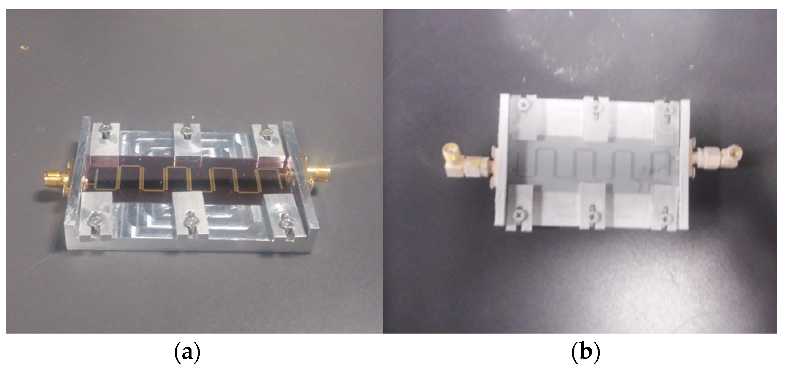
2. Filter Design, Simulations, Implementation, and Packaging Optimization

The critical components of front-ends are filters. Since HTSCs have the advantage of very low resistivity, we chose to implement the filters in an HTSC material, YBa2Cu3O7-x, to obtain a high-performance front-end. YBa2Cu3O7-x, also known as YBCO or Y-123, is a ceramic layer of Yttrium and Barium combined with copper-oxide. The YBCO critical temperature, i.e., the temperature in which it enters the superconducting state, is around 92 K. The high critical current density of YBCO, i.e., the maximum current allowed in the superconducting phase, around 3 MA/cm2, enables handling high-transmission power in relatively narrow lines [26].
The geometry and dimensions of the filter were investigated by simulations using the ANSYS HFSS software. We compared two types of filters: a conventional one made out of copper (Cu), and a superconducting filter, based on YBCO thin films. Both types of filters were implemented on sapphire substrates. For the ground plane, the other side of the substrates was fully coated with uniform layers of 1 µm-thick Cu (for the conventional filter) and 330 nm-thick perfect conductor (for the superconducting filter). Increasing the number of poles narrows the transition realm of both types of filters. Clearly, the losses of conventional filters increase significantly with the increased number of poles, whereas the losses of superconducting filters remain unchanged. However, we chose a rather small number of poles, an 8-order filter geometry, to produce a compact configuration.
To obtain high-quality coupling, along with a high Q factor, we selected the hairpin microstrip structure for the filters of the RF front-end. Figure 1 shows the geometry of the 8-order filter. For the substrate, we used a sapphire with a dielectric constant of 11.6 and a tan loss (tan δ) of 2∙10−8 [27]. The substrate was 0.43 mm-thick and had lateral dimensions of 71.4 × 25.4 mm2. Low dielectric loss and high permittivity of the sapphire substrate make it attractive for RF applications. In addition, this substrate is very suitable for YBCO thin layers deposition. In order to achieve a uniform critical current density, the surface of the sapphire dielectric substrate was polished to a roughness of 0.5 nm, and the R-plane was cut with a tolerance of ±2° and a flatness of 4–5 waves per inch. As a result, the minimal critical current density was 3.23 MA/cm2. This result should be compared to a minimal critical current density of ~1 MA/cm2 and a larger non-uniformity of the critical current density for a roughness of 2 nm [28]. The physical parameters of the filter are summarized in Table 1.
We performed extensive electromagnetic simulations of the filter’s performance to obtain the optimal dimensions of the microstrip. Figure 2 shows the transmission coefficient, S21, as a function of frequency, as derived from the simulations for the superconducting YBCO filter. The transmission coefficient is defined as the ratio of the square root of the output power to the input power. We set conductor selection as “perfect conductor” (PEC) to imitate the resistance superconductor. The filter characteristic shows a mid-frequency of ~2 GHz and a bandwidth of around 0.3 GHz. According to the results presented in Figure 2, we estimate a transmission coefficient of around 0.13 dB.
Based on the results of the optimized configuration derived from the simulations, we implemented two filters: a conventional Cu filter and a superconducting YBCO filter. The fabrication process was performed by Ceraco GmbH, Germany. It includes a wet etching and the deposition of Cu and YBCO on the wafers. In addition, the fabrication process includes growing layers on both sides of the substrate, a 330 nm-thin layer of YBCO (superconducting filter), and a 1 um-thick Cu layer (conventional filter). In both configurations, the upper-side conductors were implemented as the hairpin filters’ geometry, and the bottom side served as a uniform layer for the filters’ ground plane. Both filters were placed inside an aluminum package (Figure 3). To form high-quality contacts, the tips of the filter feedlines were coated with gold (Figure 1) [29]. The SMA connectors were attached to these tips using an indium–silver alloy and silver paint.
Following preliminary measurements, filter packaging was optimized to improve integration between the filters and the LNA. The package optimization includes three main steps: adding a packaging top cover, introducing silver paint between the filter ground plane and packaging, and mechanical reinforcement of the filter to the substrate. The reinforcement was conducted by screwing aluminum pieces placed on the filter (Figure 3), thus strengthening coupling between the filter and the package. Figure 4 shows the measured transmission coefficients S21 of the filter before and after repackaging. At the center frequency, the value of S21 remains unchanged, around 0.15 dB throughout the filter bandwidth. After package optimization, the out-of-band frequency rejection was improved by up to 28 dB. One can see that the mid-frequency of the fabricated filter is shifted by ~0.1 GHz as compared with the simulated filter module, for both packages. This ~5% difference can be attributed to production tolerances and to the fact that the material defined in simulations was PEC and not YBCO [30]. With the copper-based filter, we measured a maximum transmission coefficient of around 1.7 dB only.

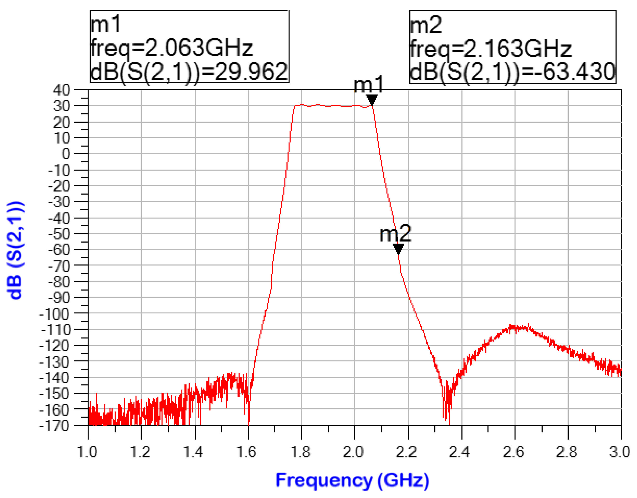
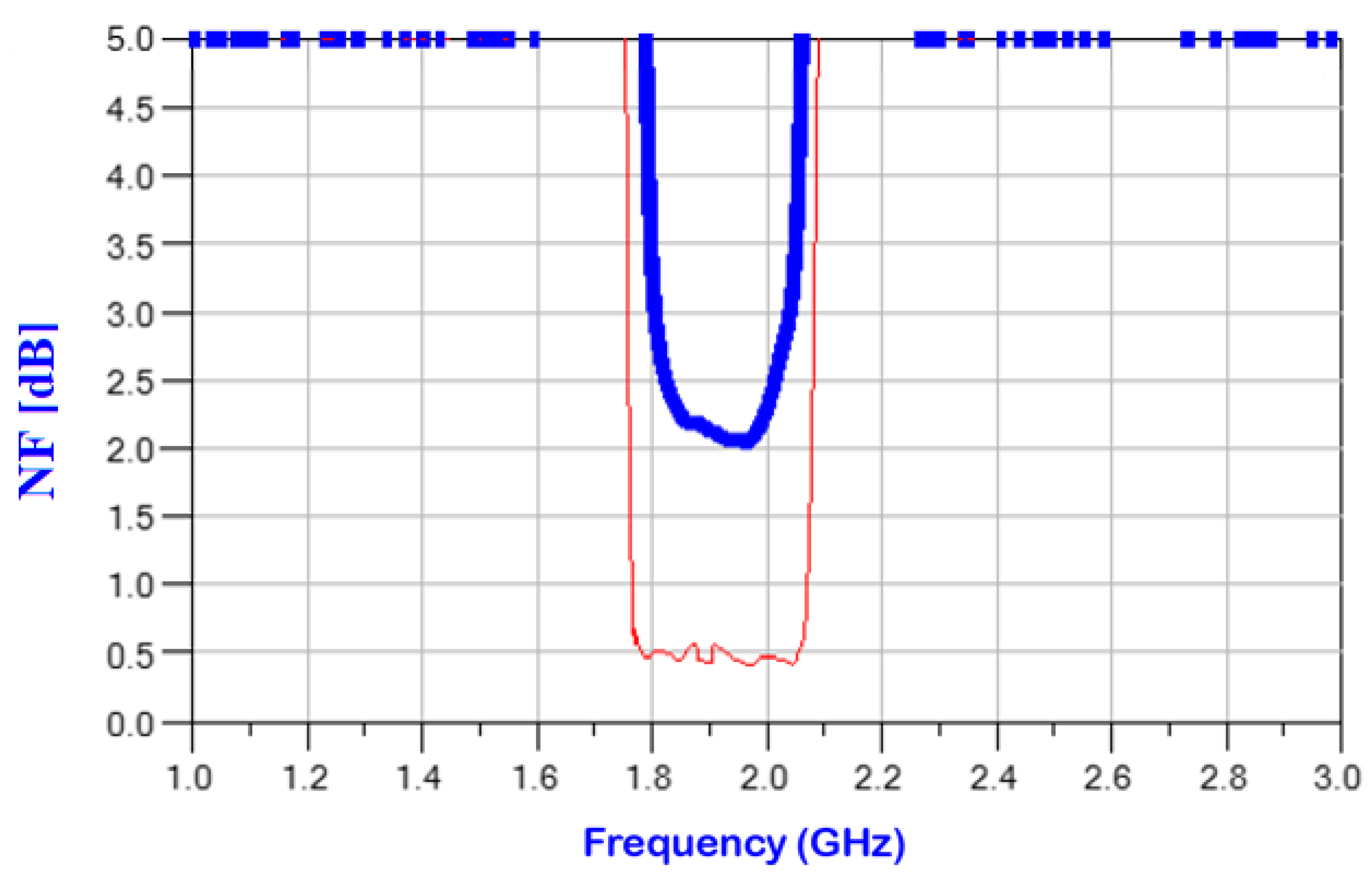
3. RF Front-End Experimental Results

To experimentally evaluate the performance of the radio head under real temperature conditions, we measured its transmission coefficient. The experimental investigation was performed with the front-end cooled to liquid nitrogen temperature (~77 K). We calibrated the measurement setup for the low-temperature operation. The cryogenic measurement setup is described in Appendix A. We used the Cosmic Microwave Technology CITLF4 amplifier as the LNA, intended for operation at low temperatures. Its specified NF is less than 1.5 dB at 300 K, and down to ~0.12 dB at 20 K.
A block diagram of the RF front-end, consisting of two HTSC BPFs and the CITLF4 LNA, is shown in Figure 5. We added the first HTSC BPF, located in front of the LNA, to improve stopband rejection.
Figure 6 presents the measured transmission coefficient of the superconducting RF head. The measured central frequency is around 2 GHz. The RF head rejection capability, for a channel 100 MHz away from the central channel, at m2, is at least −93 dBc. High rejection improves the operation of farther frequency channels.
A comparison between the measured NFs of the RF heads, with filters implemented in YBCO (thin red line) and copper (thick blue line), is presented in Figure 7. In the band of 1.8 GHz to 2.1 GHz, the measured NF for the YBCO-based system is 0.5 dB. For the copper-based system, NF = 2 dB is obtained. Moreover, in the copper head, the noise is large at the edges of the domain due to high ohmic losses leading to a low Q factor.

4. Conclusions

We have implemented an RF front-end incorporating very high-performance HTSC BPF. The implementation of the filters in superconducting materials renders superior results due to extremely low impedance. We used advanced growth techniques of the YBCO filters, replacing the gold coating with a dielectric coating. Gold coating is frequently used to protect the superconducting layer. However, electromagnetic interaction between the gold and the propagating microwaves may cause losses.
We implemented the two filters on either side of the substrate, thus obtaining superior performance in a compact configuration with superconducting 8-pole filters. As a result of the optimal design, based on extensive simulations, we measured losses of only 0.15 dB at around 2 GHz, a frequency range used extensively for cellular communication. The transmission coefficient drops very rapidly outside the central frequency range. Moreover, the front-end size is compact, using a relatively small number of poles, making its applicability more attractive despite the cryogenic requirements. Combining two optimized HTSC filters, one at the input of the LNA and one at the output, we were able to obtain excellent performance of around 2 GHz, with a low noise figure of 0.5 dB.

Author Contributions

Conceptualization, M.M. and E.H.; methodology, E.H. and M.M.; software, M.M.; validation, S.E.S., E.H., and E.F.; investigation, N.C., M.M., and E.H.; writing—original draft preparation, E.H.; writing—review and editing, S.E.S., N.C. and E.H.; experiments were performed by, M.M. and E.H.; supervision, E.H. and E.F.; funding acquisition, E.F. and S.E.S. All authors have read and agreed to the published version of the manuscript.

Funding

This research received no external funding.

Data Availability Statement

The data presented in this study are available on request from the corresponding author.

Conflicts of Interest

The authors declare no conflict of interest.

Appendix A

The cryogenic measurement system is illustrated in Figure A1. The system is composed of three main elements: a Vector Network Analyzer (VNA), a computing system, and a polystyrene liquid-nitrogen container [30,31]. The S-Parameters were measured using the VNA, and the Device Under Test (DUT) was immersed in liquid nitrogen. The VNA was calibrated using a standard calibration procedure, using through connections and three loads: open (high impedance), short, and 50 Ohms (matched), eliminating the effects of all components beside the DUT from the measured data. Since the VNA has two inputs and the device has three ports, several measurements are required to obtain all the S-Parameters. While testing the scattering coefficients of two out of three ports, the third was connected to a matching impedance, which was a load of 50 Ohms.
Figure A1. Illustration of the S-Parameter measurement setup.
Electronics 11 01270 g0a1

References

  1. Zhan, C.; Yao, G. Optimizing Caching Placement for Mobile Users in Heterogeneous Wireless Network. In Proceedings of the 2017 IEEE 42nd Conference on Local Computer Networks (LCN), Singapore, 9–12 October 2017; pp. 175–178. [Google Scholar]
  2. Barazzetta, M.; Micheli, D.; Bastianelli, L.; Diamanti, R.; Totta, M.; Obino, P.; Lattanzi, R.; Moglie, F.; Primiani, V.M. A comparison between different reception diversity schemes of a 4G-LTE base station in reverberation chamber: A deployment in a live cellular network. IEEE Trans. Electromagn. Compat. 2017, 59, 2029–2037. [Google Scholar] [CrossRef]
  3. Stavrou, V.N.; Tsoulos, I.G.; Mastorakis, N.E. Transformations for FIR and IIR filters’ design. Symmetry 2021, 13, 533. [Google Scholar] [CrossRef]
  4. Tsoulos, I.G.; Stavrou, V.; Mastorakis, N.E.; Tsalikakis, D. GenConstraint: A programming tool for constraint optimization problems. SoftwareX 2019, 10, 100355. [Google Scholar] [CrossRef]
  5. Reza, A.; Vatsa, V.; Pose, M.S.; Mazumdar, A.; Garai, A.; Krishnamoorthy, H.; Gupta, G.; Nanal, V.; Pillay, R.G.; Shrivastava, A. A cryogenic front-end preamplifier operating at 120 K for bolometric detector. J. Low Temp. Phys. 2020, 199, 200–205. [Google Scholar] [CrossRef]
  6. Mazierska, J. Superconducting cryogenic front end receivers. In Proceedings of the 15th International Conference on Microwaves, Radar and Wireless Communications, Phoenix, AZ, USA, 17–19 May 2004; pp. 351–354. [Google Scholar]
  7. Lancaster, M.J. Passive Microwave Device Applications of High-Temperature Superconductors, 1st ed.; Cambridge University Press: Cambridge, UK, 1997; Chapter 1, pp. 36–40; Chapter 2, pp. 50–55; Chapter 3, pp. 105–117. [Google Scholar]
  8. Kawaguchi, T.; Ikeuchi, H.; Kayano, H.; Sawahara, Y.; Shiokawa, N. High-sensitivity HTS multi-channel receiver front-end for 900 MHz band mobile base station. In Proceedings of the 2017 European Radar Conference (EURAD), Nuremberg, Germany, 11–13 October 2017; pp. 449–452. [Google Scholar]
  9. Holdengreber, E.; Mizrahi, M.; Glassner, E.; Dahan, Y.; Castro, H.; Farber, E. Design and implementation of an rf coupler based on YBCO superconducting films. IEEE Trans. Appl. Superconduct. 2015, 25, 1–5. [Google Scholar] [CrossRef]
  10. Holdengreber, E.; Mizrahi, M.; Farber, E. Quasi-dynamical multi-channel coupler based on high temperature superconducting films. In Proceedings of the 2012 IEEE 27th Convention of Electrical and Electronics Engineers in Israel, Eliat, Israel, 14–17 October 2012; pp. 1–4. [Google Scholar]
  11. Huhtinen, H.; Ulriksson, J.; Malmivirta, M.; Järvinen, J.; Jha, R.; Awana, V.P.S.; Vasiliev, S.; Paturi, P. Deposition of YBCO thin films in view of microwave applications. IEEE Trans. Appl. Superconduct. 2017, 27, 1–5. [Google Scholar] [CrossRef]
  12. Jasim, S.E.; Jusoh, M.A.; Yeow, Y.K.; Jose, R. A high return loss of microwave bandpass filter using superconducting electrospun YBCO nanostructures. Prog. Electromagn. Res. C 2018, 81, 63–75. [Google Scholar] [CrossRef] [Green Version]
  13. Collado, C.; Mateu, J.; Menendez, O.; O’Callaghan, J.M. Nonlinear distortion in a 8-pole quasi-elliptic bandpass HTS filter for CDMA system. IEEE Trans. Appl. Supercond. 2005, 15, 992–995. [Google Scholar] [CrossRef]
  14. Gurevich, A.; Kubo, T. Surface impedance and optimum surface resistance of a superconductor with an imperfect surface. Phys. Rev. B 2017, 96, 184515. [Google Scholar] [CrossRef] [Green Version]
  15. Abu-Hudrouss, A.M.; Jayyousi, A.B.; Lancaster, M.J. Triple-band HTS filter using dual spiral resonators with capacitive-loading. IEEE Trans. Appl. Supercond. 2008, 18, 1728–1732. [Google Scholar] [CrossRef]
  16. Zhang, T.; Yang, K.; Luo, Z. Development of integration HTSC linear phase filter with external equalization. IEEE Trans. Appl. Supercond. 2013, 23, 1501805. [Google Scholar] [CrossRef]
  17. Wang, K.; Otis, B.; Wang, Z. A 580-μ W 2.4-GHz ZigBee receiver front end with transformer coupling technique. IEEE Microw. Wirel. Compon. Lett. 2018, 28, 174–176. [Google Scholar] [CrossRef]
  18. Han, J.; Kwon, K. RF receiver front-end employing IIP2-enhanced 25% duty-cycle quadrature passive mixer for advanced cellular applications. IEEE Access 2020, 8, 8166–8177. [Google Scholar] [CrossRef]
  19. Kim, Y.; Han, J.; Lee, J.S.; Jin, T.; Jang, P.; Shin, H.; Lee, J.; Cho, T.B. Power-efficient CMOS cellular RF receivers for carrier aggregation according to RF front-end configuration. IEEE Trans. Microw. Theory Tech. 2021, 69, 452–468. [Google Scholar] [CrossRef]
  20. Ginzberg, N.; Regev, D.; Tsodik, G.; Shilo, S.; Ezri, D.; Cohen, E. A full-duplex quadrature balanced RF front end with digital pre-PA self-interference cancellation. IEEE Trans. Microw. Theory Tech. 2019, 67, 5257–5267. [Google Scholar] [CrossRef]
  21. Son, K.Y.; Kim, T.; Kwon, K. A dual-band CMOS tunable duplexer employing a switchable autotransformer for highly integrated RF front ends. IEEE Microw. Wirel. Compon. Lett. 2019, 29, 495–497. [Google Scholar] [CrossRef]
  22. Du, J.; Wang, J.; Zhang, T.; Bai, D.; Guo, Y.J.; He, Y. Demonstration of a portable HTS MMIC microwave receiver front-end. IEEE Trans. Appl. Supercond. 2015, 25, 1–4. [Google Scholar] [CrossRef]
  23. Akasegawa, A.; Yamanaka, K.; Nakanishi, T.; Kai, M. 4 GHz band HTS receiving-filters for a compact cryogenic receiver front-end. In Proceedings of the 2005 Asia-Pacific Microwave Conference Proceedings, Shuzou, China, 4–7 December 2005; p. 4. [Google Scholar]
  24. Liu, B.; Xu, M.; Yin, Y.; Song, K.; Yang, Y. Design of HTS microstrip filters for mobile communications application. In Proceedings of the 2011 China-Japan Joint Microwave Conference, Hangzhou, China, 20–22 April 2011; pp. 1–4. [Google Scholar]
  25. Bian, Y.; Guo, J.; Gao, C.; Li, C.; Li, H.; Wang, J.; He, Y. A miniaturized HTS microwave receiver front-end subsystem for radar and communication applications. Phys. C Supercond. 2010, 470, 617–621. [Google Scholar] [CrossRef]
  26. Komashko, V.A.; Popov, A.G.; Svetchnikov, V.L.; Pronin, A.V.; Melnikov, V.S.; Yu Galkin, A.; Pan, V.M.; Snead, C.L.; Suenaga, M. Critical current density of thin YBCO films on buffered sapphire substrates. Supercond. Sci. Technol. 2000, 13, 209–214. [Google Scholar] [CrossRef]
  27. Krupka, J.; Derzakowski, K.; Tobar, M.; Hartnett, J.; Geyer, R.G. Complex permittivity of some ultralow loss dielectric crystals at cryogenic temperatures. Meas. Sci. Technol. 1999, 10, 387–392. [Google Scholar] [CrossRef]
  28. Dahan, Y.; Holdengreber, E.; Mizrahi, M.; Schacham, S.; Farber, E. Multichannel transmitting system based on high-temperature superconducting phase shifter. IEEE Trans. Appl. Supercond. 2020, 30, 1–6. [Google Scholar] [CrossRef]
  29. Yang, W.I.; Lee, S.; Jung, H.S.; Kim, H.R.; Lee, S.Y. Homogeneity in the microwave surface resistance of large YBa2Cu3O7−δ superconductor films coated with Au. Electron. Mater. Lett. 2020, 16, 216–223. [Google Scholar] [CrossRef]
  30. Dahan, Y.; Holdengreber, E.; Glassner, E.; Sorkin, O.; Schacham, S.E.; Farber, E. Measurement of electrical properties of superconducting YBCO thin films in the VHF range. Materials 2021, 14, 3360. [Google Scholar] [CrossRef] [PubMed]
  31. Citron, N.; Holdengreber, E.; Sorkin, O.; Schacham, S.E.; Farber, E. High-Performance RF Balanced Microstrip Mixer Configuration for Cryogenic and Room Temperatures. Electronics 2022, 11, 102. [Google Scholar] [CrossRef]
Figure 1. The 8-order hairpin line microstrip geometry of YBCO filter.
Electronics 11 01270 g001
Figure 2. Simulation results of the transmission coefficient, S21, vs. frequency, of YBCO filter.
Electronics 11 01270 g002
Figure 3. Two packaged filters: (a) conventional Cu; (b) superconducting YBCO thin film.
Electronics 11 01270 g003
Figure 4. Measured S21 for the preliminary package (thick blue) and improved packaging (thin red) vs. frequency.
Electronics 11 01270 g004
Figure 5. RF front-end block diagram with HTSC filters.
Electronics 11 01270 g005
Figure 6. Transmission coefficient of the HTSC radio head.
Electronics 11 01270 g006
Figure 7. Comparison of noise figures of a superconductor-based (thin red) and a copper-based (thick blue) RF head.
Electronics 11 01270 g007
Table 1. Geometric dimensions of the HTSC filter.
ParameterValue
Sapphire width (substrate) 0.43 mm
YBCO width 0.625 mm
YBCO thickness330 nm
Pole width8.25 mm
Pole length10.125 mm
Publisher’s Note: MDPI stays neutral with regard to jurisdictional claims in published maps and institutional affiliations.

