Article

Modeling of Multiscale Wave Interactions Based on an Iterative Scheme of MoM-PO-EPA Algorithm

1
Beijing National Research Center for Information Science and Technology (BNRist), Department of Electronic Engineering, Tsinghua University, Beijing 100084, China
2
Theory Lab, Huawei Company, Hong Kong, China
*
Author to whom correspondence should be addressed.
Electronics 2022, 11(7), 990; https://doi.org/10.3390/electronics11070990
Submission received: 24 February 2022 / Revised: 22 March 2022 / Accepted: 22 March 2022 / Published: 23 March 2022

Abstract

:
Electromagnetic modeling of multiscale wave interactions is a challenging task. This is because wave physics exhibit different characteristics at different length scales that require suitable modeling algorithms. Combining these algorithms to model multiscale wave physics requires careful design and tuning. In this study, we investigated a hybrid algorithm based on the method of moment (MoM), iterative physical optics (IPO) approximation, and the equivalence principle algorithm (EPA). EPA modeled targets with details, MoM modeled targets with moderate scales, and IPO modeled electrically large scatterers. The virtual equivalence surfaces in EPA worked as interfaces between relatively large and small scatterers. An iterative scheme is used to solve the targets instead of a matrix equation with large dimensions. This algorithm achieved a good balance between accuracy and efficiency. Numerical examples of modeling the plane-wave scattering of multiscale targets verify its performance for 2D and 3D problems. The iterative scheme can become faster and need less memory usage when solving the multiscale scatterers.

1. Introduction

The modeling of multiscale targets using electromagnetic wave scattering is important for computational electromagnetic fields. It has wide applications in modeling wave propagation in complex environments [1,2]. Domain decomposition schemes are often adopted so that targets with different scales can be modeled separately [3,4]. Several innovative algorithms have been developed for improving the efficiency [5,6]. Among these algorithms, based on the Huygens principle, the equivalence principle algorithm (EPA) provides a flexible framework for solving multiscale problems. In this algorithm, virtual equivalence surfaces are introduced, and the interactions between targets are substituted with interactions between the equivalence surfaces [7,8,9,10,11]. With the EPA, the number of unknowns can be reduced and the matrix equations are better conditioned, compared to solving multiscale problems directly.
Domain decomposition allows each subdomain to be solved using suitable solvers. Hybridized algorithms based on the EPA have been studied [12,13,14]. For models with both electrically large and small features, high-frequency solvers can be used for large targets, such as geometric optics (GO) [15,16], physical optics (PO) [17,18], physical theory of diffraction (PTD) [19,20], and shooting and bouncing ray (SBR) techniques [21,22]. They can efficiently compute the scattered field for a large smooth surface. PO directly computes the current on the surface of the scatterers, assuming that the surface is infinite and flat [23,24]. It is easy to implement and is sufficiently accurate for electrically large and smooth surfaces. For scatterers with complex geometries and inhomogeneous dielectrics, PO can be hybridized with method of moments (MoM) to maintain its accuracy [25,26]. Electrically large and smooth subdomains can be solved by PO, while electrically small subdomains can be solved by full-wave solvers such as MoM [14], the finite element method (FEM) [27], or the finite difference time domain (FDTD) method [15].
In this study, we investigate an iterative scheme to hybridize the MoM, PO, and EPA. In this scheme, the entire domain was partitioned into subdomains based on their electrical scales. Moderate scale parts were modeled by MoM, Electrically large and smooth parts were modeled with PO, and the EM scattering of small parts with fine details was computed using the EPA. The mutual couplings among the subdomains was computed through an iterative process to accelerate this process. This scheme can improve the efficiency of multiscale modeling while maintaining a reasonable accuracy. The remainder of this paper is organized as follows: a formulation based on integral equations is presented in Section 2. In Section 3, the numerical examples are discussed to verify the accuracy and efficiency of the proposed scheme. Conclusions and discussion are presented in Section 4 and Section 5.

2. Formulation

2.1. Scattering by Multiple PEC Targets

The radiation of the surface electric current on perfect electric conductors (PECs) in a homogeneous background can be modeled using integral operators as [28,29]
E ( r ) = L ( J ¯ ( r ) )
H ¯ ( r ) = K ( J ¯ ( r ) )
Here we normalize the electric current and magnetic field with wave impedance η 0 such that the operators are more symmetric, which are
J ¯ = η 0 J , H ¯ = η 0 H
The integral operators are defined as
L ( X ) = j k 0 S X ( r ) G 0 ( r , r ) + 1 k 0 2 · X ( r ) G 0 ( r , r ) d r K ( X ) = S X ( r ) × G 0 ( r , r ) d r
Here X ( r ) is the electric current or magnetic current. G 0 ( r , r ) is the free space Green function, k 0 is the wavenumber.
To compute EM scattering by multiple PEC targets, as shown in Figure 1, we can discretize the surface electric current with basis functions and apply the MoM to establish the matrix equation of the current coefficient. For the three-target model, as shown in Figure 1, the electric field integral equation (EFIE) can be written as [29]
Z 11 Z 12 Z 13 Z 21 Z 22 Z 23 Z 31 Z 32 Z 33 · j 1 j 2 j 3 = v 1 v 2 v 3
In the above equation, Z m n represents the EM interaction between targets m and n (when m = n , which is the self-interaction of target m). It is a discrete version of the integral operator L (or K ) [5]. j m and v m ( m = 1 , 2 , 3 ) represent the discrete electric current and excitating voltage on target m, respectively. The dimension of Equation (5) is proportional to the number of basis functions on the target after discretization. When the electrical size of the targets increases or the targets contain fine features, the dimension of the matrix equation increases and the matrix becomes more ill-conditioned. All these factors make the matrix equation difficult to solve.

2.2. Physical Optics

The PO can be used to compute the surface electric current on large and smooth surfaces. Considering the propagation of EM waves as rays, the target can be split into illuminated and dark regions. The induced current under the incident field E i n c , H i n c can be approximated as [30]
J P O ( r ) = 2 n ^ × H i n c ( r ) r Illuminated region 0 r Dark region
Definition of the illuminated and dark regions can be found in [23]. This process can also be written in matrix form as
I 0 0 I · j i P O j d P O = 2 n ^ × H i n c 0
where I is the identity operator. j i P O and j d P O represent the discrete current in the illuminated and dark regions, respectively.

2.3. Equivalence Principle Algorithm

The EPA is based on the equivalence principle algorithm and can be used to improve the computational efficiency of multiscale modeling. In EPA, virtual equivalence surfaces are introduced to enclose targets with fine details (Figure 2). The EM characteristics of the target can be described using the scattering operator of the equivalent surface. Given the incident equivalent electric current J ¯ i n c = n ^ × H ¯ i n c = η 0 n ^ × H i n c and the magnetic current M i n c = n ^ × E i n c , the scattered equivalent currents on the equivalent surface can be computed as [7,8,9,10,11]
j ¯ s c a m s c a = S · j ¯ i n c m i n c
where the scattering operator S is defined as
S = n ^ × K o i n ^ × L o i · L i i 1 · L i o K i o
The subscripts o i and i o define the inside-out and outside-in operators, respectively, which describe the interaction between the current on the equivalence surface and the target inside. L i i represents the MoM matrix used to solve for the current on the target. [ · ] 1 means the matrix inverse. Details of the EPA operators can be found in [7].

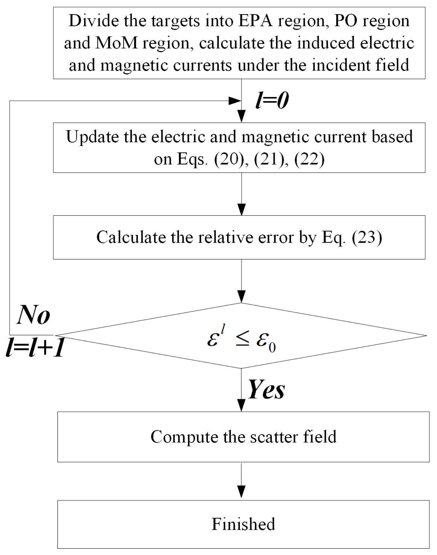
2.4. Hybrid MoM-PO-EPA and the Iterative Scheme
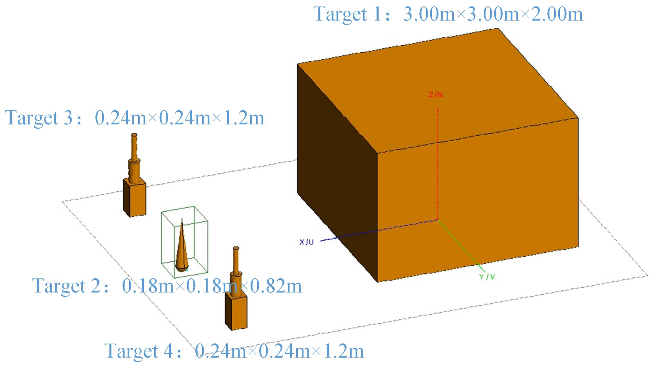
For three separate targets, as shown in Figure 1, EM scattering can be computed using a hybrid algorithm of MoM, PO, and EPA. In this example, Target 1 is solved by the MoM, Target 2 is solved by the PO because it is electrically large and smooth, and Target 3 is solved by the EPA with an equivalent surface S. The matrix equation can then be set as
Z M M Z M P Z M E Z P M Z P P Z P E Z E M Z E P Z E E · j 1 M j 2 P jm ¯ 3 E = v 1 M v 2 P v 3 E
where M, P and E are the abbreviations of MoM, PO, and EPA, respectively. The superscript “ij” means the coupling interaction from the target solved by “j” to the target solved by “i” ( i , j = M , P , E ). For example, Z M P means the coupling interaction from Target 2 solved by PO to Target 1 solved by MoM; when i = j , the matrix block in Equation (10) represents the self-interaction. This scheme is used for the separate scatterers. j 1 M and j 2 P represent the discrete electric current on target 1, target 2. v 1 M and v 2 P represent the excitating voltage on target 1, target 2. They are the same to the right hands of Equations (5) and (6). jm ¯ 3 E denotes the scattering electric and magnetic current and v 3 E represents the incident components in the equivalent surface of Target 3, they are written as
jm ¯ 3 E = j ¯ s c a m s c a v 3 E = S 3 · j ¯ i n c m i n c
Details in Equation (10) are calculated in the discrete forms (the Galerkin method) as
Z m n M M = Λ m M , L ( Λ n M )
Z m n M P = Λ m M , L ( Λ n P )
Z M E = Z M E j Z M E m , Z m n M E j = Λ m M , L ( Λ n E j ) , Z m n M E m = Λ m M , K ( Λ n E m )
Z m n P M = 2 n ^ m , I l × K ( Λ n M )
Z m n P P = Z m n E E = δ m n
Z P E = Z P E j Z P E m , Z m n P E j = 2 n ^ m , I l × K ( Λ n E j ) , Z m n P E m = 2 n ^ m , I l × L ( Λ n E m )
Z E M = S 3 · Z E j M Z E m M , Z m n E j M = n ^ m × K ( Λ n M ) , Z m n E m M = n ^ m × L ( Λ n M )
Z E P = S 3 · Z E j P Z E m P , Z m n E j P = n ^ m × K ( Λ n P ) , ; Z m n E m P = n ^ m × L ( Λ n P )
In the equations above, Λ M and Λ P represent the basis (testing) functions of the electric current on targets 1 and 2, respectively. Λ E j and Λ E m denote the basis (testing) functions of electric and magnetic currents on the equivalent surface. m and n represent the indices of the testing and basis functions (the Galerkin method is used). n ^ m is the unit normal vector of the m-th testing function. n ^ m , I l represent the unit normal vector of the basis functions in the illuminated regions of target 2. The value could be set as zero in dark regions. Note that the illuminated regions vary along the incident field [31]. S ¯ 3 is the discrete form of the scattering operator S of Target 3 [7].
When the dimensions of the targets are large, solving Equation (10) directly becomes difficult. Here, we adopted an iterative scheme to reduce the computational bottleneck. In this scheme, by solving Equation (10), it could be decomposed into an iterative process by solving the following equations
Z M M · j 1 M , l + 1 = v 1 M Z M P · j 2 P , l Z M E · jm ¯ 3 E , l
j 2 P , l + 1 = v 2 P Z P M · j 1 M , l + 1 Z P E · jm ¯ 3 E , l
jm ¯ 3 E , l + 1 = v 3 E Z E M · j ¯ 1 M , l + 1 Z E P · j 2 P , l + 1
In the equations above, l denotes the iteration count. The first part on the right-hand side of Equations (20)–(22) represent the exciting voltages of the incident wave. The second and third parts represent the radiation from other targets. Note that the illuminated and dark regions in Target 2 vary with the radiation source. To determine the illuminated and dark regions, we applied the z-buffer technique [19] for illumination by the incident plane wave, and the near-field z-buffer technique [31] for radiation from other targets.
In every iteration, Equations (20)–(22) were solved sequentially. The relative error of the current coefficients at the l-th iteration is computed as
ε l = i = 1 M j i l j i l 1 j i l 1 l = 1 , 2 ,
Here, · is the L 2 -norm, j i l means the electric and magnetic current coefficients of the targets, and M represents the total target numbers. The iteration stops when the relative error is less than a threshold, or the iteration step reaches a predefined maximum. In one iteration, Equation (20) should be solved by an iterative solver with a large dimension. Equations (21) and (22) describe the updated solution of targets 2 and 3 with the matrix-vector multiplications. This iterative scheme can be extended directly to multiple targets. Figure 3 shows the flowchart of this algorithm. For a target with smooth surface and large-scale dimension, PO is used; for a target with complex structures and moderate dimensions, MoM is used; for target with fine details, EPA is used. All the targets can be solved by one solver in the iterative process depending on the scales of the targets. The scheme uses different algorithms to solve different targets to satisfy the accuracy and efficiency at the same time for multiscale modelings.

3. Results

A numerical example of 2D EM scattering by multiple targets was presented to demonstrate the effectiveness and accuracy of the proposed method. The computation was executed on a computer (Intel® i5-9600K CPU @3.7GHz with 6 cores) with OpenMP parallelization. The equivalence surface was a circle enclosing the object 1 λ away from the internal target, and its mesh size was 0.125 λ ( λ represents the wavelength of the incident wave). The stopping threshold was 0.1 and the results computed by the MoM were used as benchmarks.
Two targets positioned 2.5 m above an undulating PEC surface were considered, as shown in Figure 4. Target 1 is the outer contour of a pentagram with side length 2.0 m, and the center is at (0.0 m, 2.5 m), Target 2 is an undulating line segment created randomly with length 14.0 m and height 0.5 m, Target 3 is created by rotating a U-shaped structure with a size of 1.0 m × 1.4 m at (2.5 m, 2.5 m) and wall thickness of 0.1 m (Rotating angle is 30 ) in the counter-clockwise direction. The distance between Targets 1 and 2 is 2.5 m. Five algorithms were used to solve the problem, These algorithms include MoM, EPA-PO [32], MoM-PO [30], IPO [24], and the proposed scheme. MoM solves the entire system by GMRESE, EPA-PO uses EPA to solve the upper targets, and PO solves the lower surface, and MoM-PO uses MoM to solve the upper targets with LU decomposition in Equation (20), and PO solves the lower surface, IPO uses PO to solve all the targets, and the proposed scheme uses MoM to solve Target 1 with LU decomposition in Equation (20), PO to solve Target 2, and EPA to solve Target 3.
The incident frequency was 8.0 GHz and the angle of incidence was ϕ = 60 . The radar cross section (RCS) was computed. The angle of observation ranged from 10 to 170 in steps of 0 . 5 .
The RCS values computed using different algorithms are plotted in Figure 5. The root mean square error (RMS) defined in Equation (24) ( R i is the calculating result in dB format, and R b i is the benchmark) is used to quantify the accuracy of different solvers. Figure 6 shows the error convergence of the proposed scheme. The relative error is less than 0.1 after four iterations in the proposed scheme. A comparison of CPU time, memory usage and accuracy (marked as RMS) are listed in Table 1 to validate the efficiency. The iterative scheme runs 2.3 times faster than traditional MoM with LU decomposition.
R M S = 1 N i = 1 N ( R i R b i ) 2
Figure 7 shows the 3D simulation model. Target 1 is a PEC box with size 3.00 m × 3.00 m × 2.00 m and centered at (0.00 m, 0.00 m, 0.00 m). Target 2 is a PEC cone-sphere with size 0.18 m × 0.18 m × 0.82 m and centered at (3.82 m, 0.00 m, 0.36 m). Target 3 is created by three objects, the size of the lower cube is 0.30 m × 0.30 m × 0.60 m, the middle cylinder has size 0.20 m × 0.20 m × 0.40 m, and the upper cylinder has size 0.10 m × 0.10 m × 0.50 m. The center of Target 3 is (3.82 m, −1.78 m, 0.60 m). The size of Target 4 is the same as that of Target 3, and the center position is (3.82 m, 2.02 m, 0.60 m).
The incident frequency is 0.5 GHz and the angle of incident field is ( θ , ϕ ) = ( 90 , 20 ) with HH polarization. The RCS was computed to verify the accuracy and efficiency with a scan angle ( θ , ϕ ) = ( 90 , 0 ) ( 90 , 360 ) , and the step angle is 0 . 5 . These algorithms include the MoM, IPO, and the proposed scheme. MoM is accelerated by MLFMA and solved by GMRES; IPO uses PO in every target in the iterative scheme. The proposed scheme uses PO solves target 1, EPA solves target 2, and MoM to solve targets 3 and 4 with GMRES in Equation (20). Table 2 shows the time consumption and RCS RMS (Traditional MoM is the benchmark).
The RCS values computed using different algorithms are plotted in Figure 8. The proposed scheme gives a better accuracy than IPO and a faster speed than traditional MoM. In this example, MoM took 227.0 s, IPO took 24.0 s, and MoM-IPO-EPA took 60.0 s to complete the calculation (not including the time of calculating the scattering operator).

4. Discussion

In this study, we proposed an iterative scheme for solving the multiscale scatterers with MoM, PO, and EPA hybridization. Two advantages were obtained by the scheme with high efficiency for multiscale problems. Targets can be solved with apposite algorithms based on the structures and scales. The coupling interactions were treated as the second excitation. Small matrix equations were used to model the physical mechanism to get the induced current. We can accelerate the speed with an accurate result.
PO is good at solving large-scale problems with a fast speed but with poor accuracy, while MoM has the best accuracy but encounters difficulties in the speed. The performance of EPA is between PO and MoM. The hybridization of MoM, PO, and EPA can satisfy the simulation of the multiscale scatterers. Since the PO current can be calculated timely in the simulation, the complexity depends on the MoM and EPA regions, which have lower unknowns, fortunately.
Numerical examples verify the performance of the proposed scheme. RMS was used to quantify the accuracy. The proposed method can give an accurate RCS result compared with the reference algorithm, and the efficiency was obtained as expected. In the 2D numerical examples, the RMS of the proposed scheme was 6.5 dBm, and 32.0 s was used; it was more accurate than IPO (13.1 dBm) and faster than EPA-PO (42.0 s). The accuracy is better than IPO, and the efficiency is better than EPA-PO. This phenomenon was verified in 3D scatterers too.
Although the proposed scheme shows a good performance for the multiscale scatterers, The coupling interactions among separate targets may have large dimensions (if the target has significant unknowns), and compressing the matrix blocks deserves deep research to elevate the efficiency further.

5. Conclusions

In this study, we investigated an iterative scheme for solving the EM interactions of multiple scatterers with multiscale features. Based on the hybrid MOM-EPA-PO algorithm, the interactions between different regions can be modeled using appropriate algorithms. An iterative scheme was adopted in modeling EM interactions between different targets. The coupling interactions between different targets are treated as the second excitations in an iterative process to reduce the complexity, then only a matrix equation with a small dimension needs to be solved to get a high efficiency. The proposed scheme converges to a fairly accurate solution within a few iterations. The numerical example shows that the proposed scheme can achieve a good balance between accuracy and efficiency compared to the conventional MoM.

Author Contributions

L.G. and M.L. conceived of the presented idea. L.G. developed the theory and performed of the computations. S.X. and F.Y. verified the analytical methods. J.L. encouraged L.G. to investigate the simulation model 3D by the proposed method. All authors discussed the results and contributed to the final manuscript. M.L. developed the theoretical formalism, L.G. performed the numerical calculations and performed the numerical simulations. Both L.G. and M.L. contributed to the final version of the manuscript. L.G., M.L., S.X., F.Y. and J.L. contributed to the design and implementation of the research, and to the analysis of the results of the manuscript. All authors have read and agreed to the published version of the manuscript.

Funding

This research was funded in part by the National Natural Science Foundation of China under Grant 61971263, in part by the National Key Research and Development Program of China under Grant 2018YFC0603604.

Acknowledgments

This work was supported in part by the National Natural Science Foundation of China under Grant 61971263, in part by the National Key Research and Development Program of China under Grant 2018YFC0603604, in part by HuaWei Tech. Investment Co., Limited, in part by the BirenTech Research Center, and in part by the Institute for Precision Medicine, Tsinghua University, Beijing, China.

Conflicts of Interest

The authors declare no conflict of interest.

References

  1. Zhao, J.S.; Chew, W.C. Integral equation solution of Maxwell’s equations from zero frequency to microwave frequencies. IEEE Trans. Antennas Propag. 2000, 48, 1635–1645. [Google Scholar] [CrossRef]
  2. Arvas, E.; Harrington, R.; Mautz, J. Radiation and scattering from electrically small conducting bodies of arbitrary shape. IEEE Trans. Antennas Propag. 1986, 34, 66–77. [Google Scholar] [CrossRef]
  3. Brezzi, F.; Marini, L.D. A three-field domain decomposition method. Contemp. Math. 1994, 157, 27. [Google Scholar]
  4. Hou, Y.; Xiao, G.; Tian, X. A Discontinuous Galerkin Augmented Electric Field Integral Equation for Multiscale Electromagnetic Scattering Problems. IEEE Trans. Antennas Propag. 2017, 65, 3615–3622. [Google Scholar] [CrossRef]
  5. Li, W.D.; Hong, W.; Zhou, H.X. Integral equation-based overlapped domain decomposition method for the analysis of electromagnetic scattering of 3D conducting objects. Microw. Opt. Technol. Lett. 2007, 49, 265–274. [Google Scholar] [CrossRef]
  6. Peng, Z.; Wang, X.C.; Lee, J.F. Integral Equation Based Domain Decomposition Method for Solving Electromagnetic Wave Scattering From Non-Penetrable Objects. IEEE Trans. Antennas Propag. 2011, 59, 3328–3338. [Google Scholar] [CrossRef]
  7. Li, M.K.; Chew, W.C. Multiscale simulation of complex structures using equivalence principle algorithm with high-order field point sampling scheme. IEEE Trans. Antennas Propag. 2008, 56, 2389–2397. [Google Scholar] [CrossRef]
  8. Lu, C.C.; Chew, W.C. The use of Huygens’ equivalence principle for solving 3-D volume integral equation of scattering. IEEE Trans. Antennas Propag. 1995, 43, 500–507. [Google Scholar]
  9. Li, M.K.; Chew, W.C. Using tap basis to implement the equivalence principle algorithm for domain decomposition in integral equations. Microw. Opt. Technol. Lett. 2006, 48, 2218–2222. [Google Scholar] [CrossRef]
  10. Shao, H.; Hu, J.; Nie, Z.P.; Han, G.; He, S. Hybrid tangential equivalence principle algorithm with MLFMA for analysis of array structures. Prog. Electromagn. Res. 2011, 113, 127–141. [Google Scholar] [CrossRef] [Green Version]
  11. Li, M.K.; Chew, W.C. Wave-field interaction with complex structures using equivalence principle algorithm. IEEE Trans. Antennas Propag. 2007, 55, 130–138. [Google Scholar] [CrossRef]
  12. Li, M.; Zhuang, T.; Chen, R. Volume integral equation equivalence principle algorithm domain decomposition with body of revolution equivalence surface. IET Microw. Antennas Propag. 2018, 12, 375–379. [Google Scholar] [CrossRef]
  13. Zhang, K.; Zhang, J.; Ouyang, J.; Yang, F. A novel hybrid method with equivalence principle algorithm and physical optics for antenna problems on electrically large platform. In Proceedings of the 2011 IEEE International Symposium on Antennas and Propagation (APSURSI), Spokane, WA, USA, 3–8 July 2011; pp. 2530–2532. [Google Scholar]
  14. Liu, Z.L.; Wang, C.F. Efficient iterative method of moments—Physical optics hybrid technique for electrically large objects. IEEE Trans. Antennas Propag. 2012, 60, 3520–3525. [Google Scholar] [CrossRef]
  15. Yang, P.; Liou, K. Light scattering by hexagonal ice crystals: Comparison of finite-difference time domain and geometric optics models. J. Opt. Soc. Am. A Opt. Image Sci. Vis. 1995, 12, 162–176. [Google Scholar] [CrossRef]
  16. Thompson, D.R.; Elfouhaily, T.M.; Garrison, J.L. An improved geometrical optics model for bistatic GPS scattering from the ocean surface. IEEE Trans. Geosci. Remote Sens. 2005, 43, 2810–2821. [Google Scholar] [CrossRef]
  17. Perez, J.; Catedra, M. Application of physical optics to the RCS computation of bodies modeled with NURBS surfaces. IEEE Trans. Antennas Propag. 1994, 42, 1404–1411. [Google Scholar] [CrossRef]
  18. Knott, E.F. A progression of high-frequency RCS prediction techniques. Proc. IEEE 1985, 73, 252–264. [Google Scholar] [CrossRef]
  19. Rius, J.M.; Ferrando, M.; Jofre, L. GRECO: Graphical electromagnetic computing for RCS prediction in real time. IEEE Antennas Propag. Mag. 1993, 35, 7–17. [Google Scholar] [CrossRef] [Green Version]
  20. Ufimtsev, P.Y. Elementary edge waves and the physical theory of diffraction. Electromagnetics 1991, 11, 125–160. [Google Scholar] [CrossRef]
  21. Tao, Y.; Lin, H.; Bao, H. GPU-based shooting and bouncing ray method for fast RCS prediction. IEEE Trans. Antennas Propag. 2009, 58, 494–502. [Google Scholar]
  22. Ling, H.; Chou, R.C.; Lee, S.W. Shooting and bouncing rays: Calculating the RCS of an arbitrarily shaped cavity. IEEE Trans. Antennas Propag. 1989, 37, 194–205. [Google Scholar] [CrossRef]
  23. Weinmann, F. Ray tracing with PO/PTD for RCS modeling of large complex objects. IEEE Trans. Antennas Propag. 2006, 54, 1797–1806. [Google Scholar] [CrossRef]
  24. Obelleiro-Basteiro, F.; Rodriguez, J.L.; Burkholder, R.J. An iterative physical optics approach for analyzing the electromagnetic scattering by large open-ended cavities. IEEE Trans. Antennas Propag. 1995, 43, 356–361. [Google Scholar] [CrossRef]
  25. Chen, M.; Zhao, X.W.; Zhang, Y.; Liang, C.H. Analysis of antenna around NURBS surface with iterative MoM-PO technique. J. Electromagn. Waves Appl. 2006, 20, 1667–1680. [Google Scholar] [CrossRef]
  26. Ma, J.; Gong, S.X.; Wang, X.; Liu, Y.; Xu, Y.X. Efficient wide-band analysis of antennas around a conducting platform using MoM-PO hybrid method and asymptotic waveform evaluation technique. IEEE Trans. Antennas Propag. 2012, 60, 6048–6052. [Google Scholar] [CrossRef]
  27. Fernández-Recio, R.; García-Castillo, L.; Gómez-Revuelto, I.; Salazar-Palma, M. Fully coupled multi-hybrid FEM-PO/PTD-UTD method for the analysis of radiation problems. IEEE Trans. Magn. 2007, 43, 1341–1344. [Google Scholar] [CrossRef]
  28. Peterson, A.F.; Ray, S.L.; Mittra, R.; Institute of Electrical and Electronics Engineers. Computational Methods for Electromagnetics; IEEE Press: New York, NY, USA, 1998; Volume 351. [Google Scholar]
  29. Jin, J.M. Theory and Computation of Electromagnetic Fields, 2nd ed.; Wiley-IEEE Press: New York, NY, USA, 2015. [Google Scholar]
  30. Liu, Z.L.; Wang, C.F. An efficient iterative MoM-PO hybrid method for analysis of an onboard wire antenna array on a large-scale platform above an infinite ground. IEEE Antennas Propag. Mag. 2013, 55, 69–78. [Google Scholar] [CrossRef]
  31. Bourlier, C.; Pouliguen, P. Useful analytical formulae for near-field monostatic radar cross section under the physical optics: Far-field criterion. IEEE Trans. Antennas Propag. 2009, 57, 205–214. [Google Scholar] [CrossRef]
  32. Zhang, K.; Yang, J.O.; Yang, F.; Zhang, J.; Li, Y. Analysis of multi-scale problem about antenna mounted on electrically large platform by using connected EPA-PO. Prog. Electromagn. Res. 2012, 126, 169–183. [Google Scholar] [CrossRef] [Green Version]
Figure 1. Scattering model of three targets.
Electronics 11 00990 g001
Figure 2. Huygens’ principle with an enclosing surface.
Electronics 11 00990 g002
Figure 3. The flow chart of the iterative scheme of MoM-PO-EPA.
Electronics 11 00990 g003
Figure 4. Simulating model of the two targets above a PEC surface.
Electronics 11 00990 g004
Figure 5. Comparison of RCS with different methods.
Electronics 11 00990 g005
Figure 6. The relative error v s iteration step by the proposed scheme.
Electronics 11 00990 g006
Figure 7. Simulating model of four targets in 3D.
Electronics 11 00990 g007
Figure 8. RCS by different algorithms.
Electronics 11 00990 g008
Table 1. The summary of CPU time and memory usage (‘/’ means no memory usage in IPO).
AlgorithmUnknownsMemoryTime CostRMS
MoM7544868.4.4.3 Mb1042.0 s0.0 dBm
EPA-PO3862194.9 Mb42.0 s8.12 dBm
IPO//2.0 s13.1 dBm
MoM-PO-EPA3638186.2 Mb32.0 s6.5 dBm
Table 2. The summary of CPU time and memory usage by different algorithms.
AlgorithmUnknownsMemoryTime CostRMS
MoM17,8224846.6 Mb2419.0 s0.0 dBsm
IPO//38.0 s4.8 dBsm
MoM-PO-EPA46741154.7 Mb347.0 s4.1 dBsm
Publisher’s Note: MDPI stays neutral with regard to jurisdictional claims in published maps and institutional affiliations.

