Article

Fully Implantable Neural Stimulator with Variable Parameters

College of Biomedical Engineering, Sichuan University, Chengdu 610065, China
*
Author to whom correspondence should be addressed.
Electronics 2022, 11(7), 1104; https://doi.org/10.3390/electronics11071104
Submission received: 4 March 2022 / Revised: 29 March 2022 / Accepted: 29 March 2022 / Published: 31 March 2022

Abstract

:
Neural implantable systems have promoted the development of neurosurgery research and clinical practice. However, traditional tethered neural implants use physical wires for power supply and signal transmission, which have many restrictions on implant targets. Therefore, untethered, wireless, and controllable neural stimulation has always been widely recognized as the engineering goal of neural implants. In this paper, magnetically coupled resonant wireless power transfer (MCR-WPT) technology is adopted to design and manufacture a wireless stimulator for the electrical stimulation experiment of nerve repair. In the process of device development, SCM technology, signal modulation, demodulation, wireless power supply, and integration/packaging are used. Through experimental tests, the stimulator can output single-phase pulse signals with a variable frequency of (1–20 Hz), a duty cycle of (1–50%), and voltage. The average power is approximately 25 mW. The minimum pulse width of the signal is 200 μs and the effective distance of transmission is 1–4 cm. The stimulator can perform low-frequency, safe and controllable wireless stimulation.

1. Introduction

Peripheral nerve injury is a major problem in public health, accounting for 2–5% of all trauma cases [1]. Peripheral nerve injury can lead to sensory, nutritional, and motor disturbances in the innervated area.
At present, the common repair methods for nerve injury include cell therapy [2], molecular therapy [3], and catheter therapy [4]. Additionally, studies have proved that electrical stimulation therapy can accelerate nerve regeneration after injury and promote the recovery of corresponding motor functions [5], which is characterized by good effects, small side effects, and clear action sites. Electrical stimulation can be widely used in clinical and neurological therapy and rehabilitation, and experimental electrical stimulation in animal models can be used for the preclinical evaluation of the safety and effectiveness of implantable neural prostheses, as well as for basic research on neural function and behavior. The stimulator designed in this study is modeled on rats and other small animals.
In animal model experimental studies, methods of wired percutaneous connections between arrays and external stimulators is common and convenient [6,7,8,9,10]. However, those methods have many disadvantages: (1) they restrict movement and natural behavior; (2) the wound has a high risk of potential infection; (3) the mechanical failure due to mechanical stress of exposed equipment and impact of animals. Current studies have proposed remote control neural stimulators for the movement control of small animals [11,12,13,14]. These devices can eliminate binding lines and enable animals to move unrestricted. However, there is still a percutaneous connection between the implanted cortical array and the stimulator. Battery-powered implantable stimulators can solve the problem [15], although their power capacity is limited and the use of fully implantable wireless stimulators have been demonstrated through research. The electronic components are inserted into the subcutaneous space around the scapula or head without any components outside the body [16,17]. The implant is small, light in weight, and long in life, but the frequency and intensity of the pulse stimulation are not effectively controlled.
Fortunately, the past decade has witnessed significant technical advancement on how to achieve wireless neural implants. The research of electric stimulation in animal experiments has made breakthroughs in the fields of motor control, neural decoding, and neural therapy. For example, the movement of some living insects can be controlled by implantable electrical nerve stimulation, and the speed can be adjusted by varying the frequency of stimulation [18,19,20,21]. The robotic insects could be used for search and rescue in complex environments. Moreover, Ho, J. S. et al. [22] demonstrated a wirelessly powered method for powering tiny implants almost anywhere in the body. Kate et al. [23] developed a miniature wireless stimulator to achieve photo genetic manipulation of neural circuits in the nervous system. A tiny LED was implanted into mice, and optical stimulation with blue light in the spinal cord and cerebral cortex elicited circling behavior and increased the speed of locomotion. Thanks to technological advances and the success of clinical trials, fully implantable solutions have become a reality and are now available for the treatment of nerve injury [24]. These studies provide references for our design.
Based on the above discussion, the design criteria can be proposed as follows: (1) meet the basic requirements of bioelectric stimulation; (2) precise and adjustable stimulus parameters; (3) wireless control and drive; (4) miniaturization; (5) long-term power supply capability.
Given these objectives, a novel wireless, fully implantable small neural electrical stimulator has been designed to deliver long-term, variable parameter pulse stimulation to experimental targets under natural conditions (Figure 1). This work can overcome the above technical shortcomings.
Table 1 shows the comparisons between existing research results with our work in stimulus parameters. Lu et al. [25] and Chen et al. [26] show that the stimulation current at low frequency and milliampere-level have a significant effect on promoting nerve fiber regeneration. The optimal frequency they used was below 20 Hz, and our stimulator is designed to achieve a frequency regulation of 1–20 Hz. As for single-phase stimulation and dual-phase stimulation, Chen et al. [26] show that the difference in waveform characteristics can be ignored.
The stimulator transmission distance is set to a few centimeters and the coupling frequency is set to 3 MHz. At this frequency, the energy loss associated with bioliquid absorption can be reduced [28].
In the following chapters, we introduce the circuit model manufacturing method and conduct simulation analyses and experimental verifications.

2. Materials and Methods

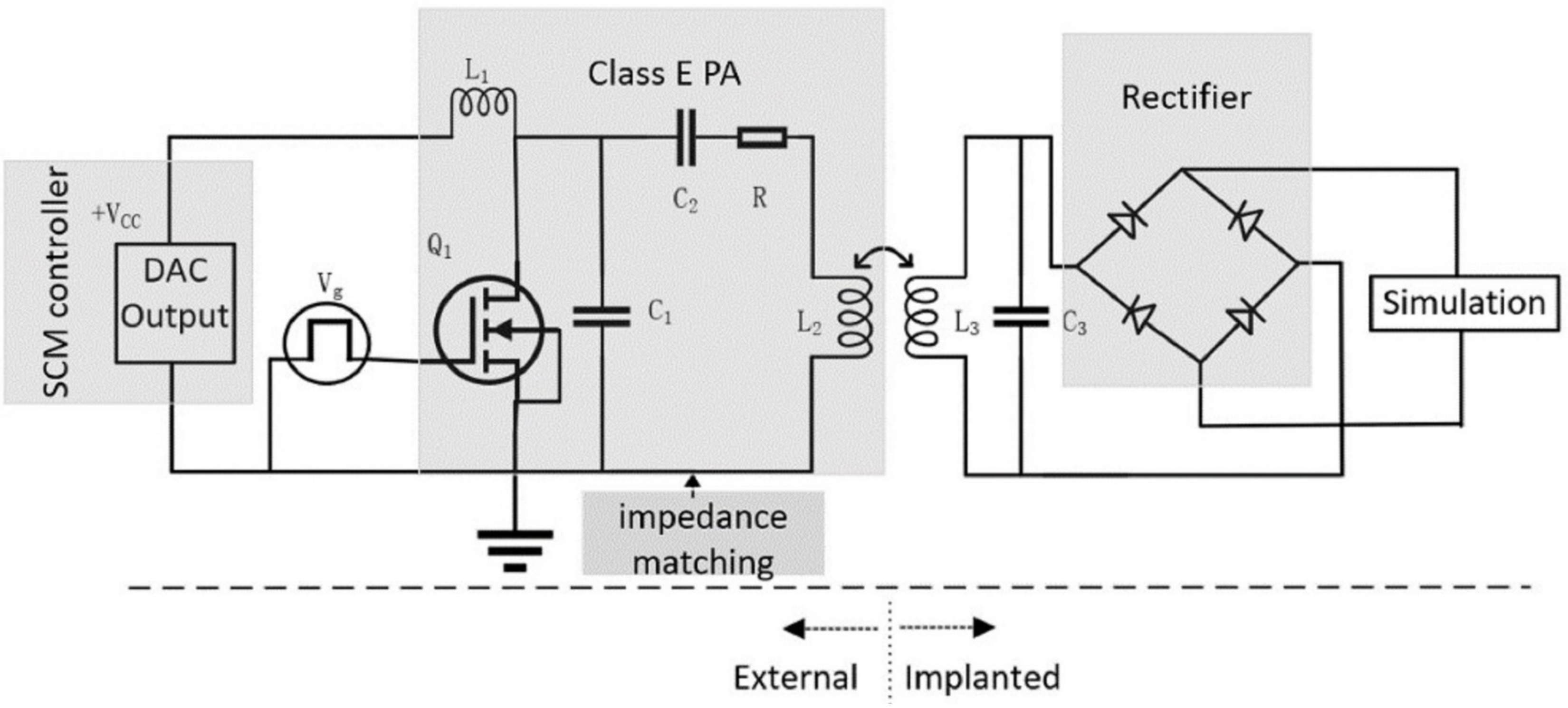
2.1. System Overview

The system consists of an implanted stimulator and an external circuit which are wirelessly connected by MCR-WPT (Figure 2). The external circuit includes a SCM (Single-Chip Micyoco) controller, impedance matching network, and the Class E PA (Power Amplifier). The assembly of the implanted stimulator consists of a rectifier and the stimulating circuit. The L2 and L3 are the transmit (Tx) and receive (Rx) coil in the MCR-WPT system, respectively. The pulse Vg is the gate drive signal. The impedance matching network will be covered in the next section.

2.2. Static Parameter Analysis

2.2.1. The External Circuit

In this work, the Class E PA is used as a power source. Among them, ZVS (Zero Voltage Switching) Class E PA has the highest working efficiency [29]. When the transistor is on, the capacitor C1 is short-circuited, and R, C2, L2 form a series resonant circuit. The resonance frequency f1 and q-factor Q1 can be described as:
f 1 = 1 2 π L 2 C 2
Q 1 = ω 1 L 2 R = 1 ω 1 C 2 R
When the transistor is disconnected, C1, R, C2, L2 form a series resonant circuit. The resonance frequency f 2 and q-factor Q2 can be described as:
f 2 = 1 2 π L 2 C 1 C 2 C 1 + C 2
Q 2 = ω 2 L 2 R = 1 ω 2 RC 1 C 2 C 1 + C 2
To ensure the efficiency of class E PA, the signal frequency ( f e ) of the driving transistor switch should be between f 1 and f 2 . We assume that the duty cycle is D = 0.5 and the choke inductance L1 is large enough. When the supply voltage VCC, the load resistance R0, the output power delivered to the load PO, the operating frequency f e and the q-factor QL is given, we can calculate circuit component parameter values from the following formula [30].
R = 0.5768 V 2 CC P O 1.001245 0.452 Q 0.4 Q 2
L 2 = QR ω
C 1 = 1 ω R 8 π π 2 + 4 0.999 + 0.914 Q 1.03 Q 2 + 0.6 Q L 1 / L 2
C 2 = 1 ω R 1 Q 0.105 1.001 + 1.015 Q 1.788 0.2 Q L 1 / L 2
Referring to circuit specifications described in [29,30], we set R0 = 50 Ω, PO = 1 W, f e = 3 MHz, and QL = 10 here. As the supply voltage of the stimulator is adjustable, and R varies from 0 to 15 Ω, we set R = 10 Ω. As this value is different from the actual load resistance Ro, we can use the π type impedance matching network to transform Ro to R. According to the design indicators in Table 1, the final component parameters are shown in Table 2. There is a comparison, f 1 = 2.81 MHz < f e = 3 MHz < f 2 = 3.48 MHz, which conforms to the design index.

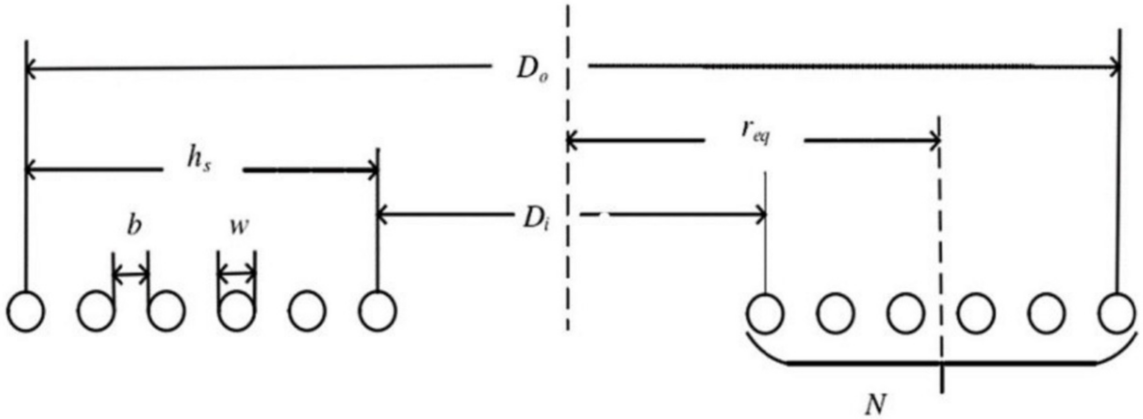
2.2.2. The Implanted Stimulator

The key point of the implanted stimulator is the design of the Rx coil L3. In our work, it adopts the manufacturing model of a planar spiral coil, and its cross-section is shown in Figure 3. The value of L can be calculated using the following formula [31]:
L = N 2 ( D 0 N w + b ) 2 16 D 0 + 28 N w + b × 39.37 10 6 H
where D0 is the outer diameter of the coil; N is the number of turns of the coil; w and b denote the diameter of wire and the spacing between the wires, respectively.
Moreover, L3 and C3 resonate at the operating frequency f e = 3 MHz and their values must satisfy the formula:
f e = 1 2 π L 3 C 3

2.3. Dynamic Analysis
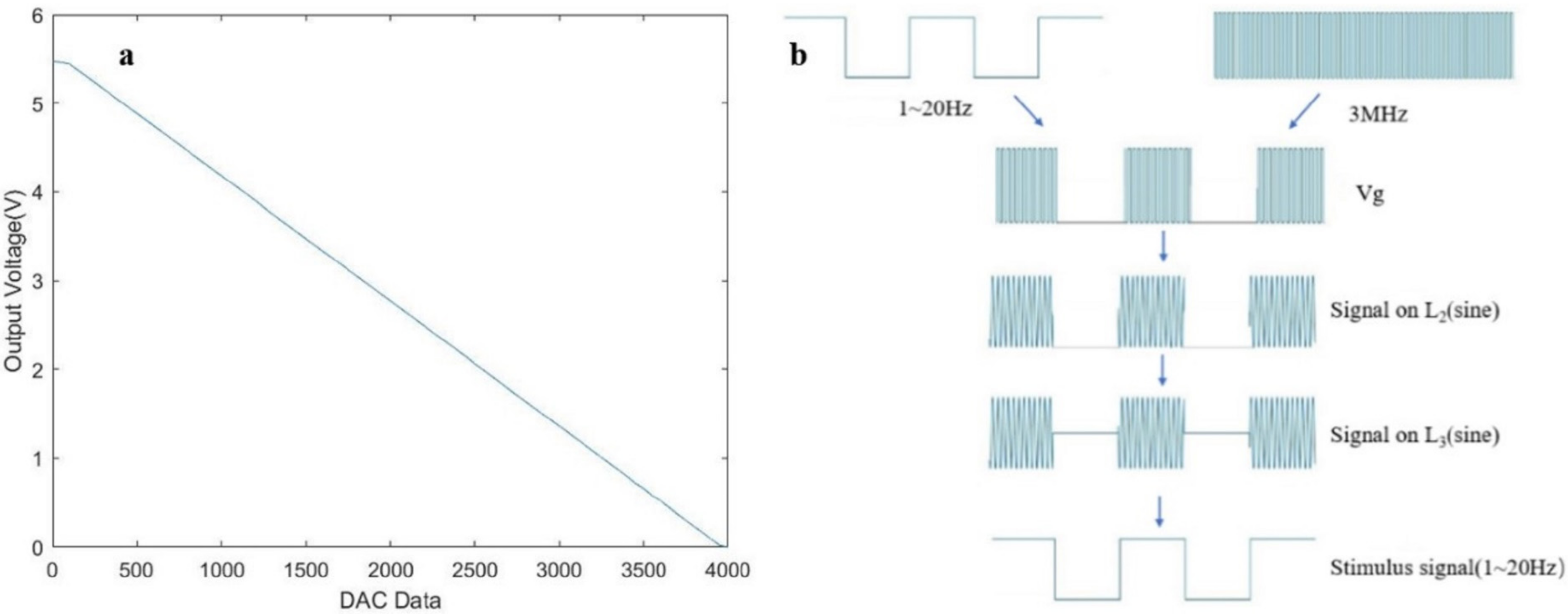
The dynamic analysis of this system mainly includes two aspects: (1) to realize the dynamic change of the supply voltage to the Class E PA from 0 to 5 V; (2) the modulation of Vg (duty ratio 1–50% and stimulation frequency 1–20 Hz). Based on the above requirements, the SCM STM32F103ZET6 development board is used as the core control board of the system.

2.3.1. DAC Output

For convenience, we use the DAC output function of STM32 to obtain the controllable dynamic voltage with the target of 0–5 V. The specific circuit is shown in Figure 4a. And the Figure 4b shows the topology of the impedance matching network we used.
The output voltage of LM317 is controlled by adjusting R1 and R2. Finally, the 0–5 V output voltage is controlled by 0–3.3 V DAC voltage in STM32. The VCC and VEE are powered by a jMD35-D18 AC-DC switching power supply. The DAC of STM32 is 12 bits, and the value can be set in the range of 0–4096 to obtain the DAC output voltage of 0–3.3 V (Figure 5a). The following formula fits the curve in Figure 5a.
Y = 3975 0.714 U
Y is the DAC data, and U is the actual output voltage (V). Here we achieve a 0–5 V power supply of the system, and the adjustment accuracy is about 0.7 mV.

2.3.2. The Signal Modulation

Generally, the electrical stimulation signals of nerve repair in rats are unfixed. We use the PWM (Pulse Width Modulation) output function of STM32 to conduct the signal modulation. In this study, TIM2 and TIM3 timers are selected to generate a high-frequency carrier and low-frequency stimulation pulse, respectively. The frequency calculation formula is:
f = 72 MHz TIM _ Period + 1 / TIM _ Prescaler + 1
The TIM_Period and TIM_Prescaler are adjustable parameters of the timers and are non-negative values. The pulse with different frequencies can be obtained by setting different parameter values (Table 3). Only a few frequencies are shown in the table. The frequency range can be expanded by setting parameters as required. The duty cycle can be controlled by comparison registers (TIMx_CCR2–3) in STM32.
Figure 5b shows the signal transmission process. The high-frequency carrier pulse and the low-frequency stimulation pulse are modulated with the AND gate to obtain the final Vg signal. The Vg signal oscillates through Class E PA to obtain the signal on L2. After that, the signal on L3 was obtained through wireless transmission. Finally, the low-frequency stimulation pulse of 1–20 Hz for neural electrical stimulation was generated through demodulation. Moreover, according to actual needs, two-timer parameters can be set to obtain a larger frequency of the stimulation pulse.
So far, the characteristic parameters of the wireless stimulator designed in this study have adjustable ranges, that is, a frequency of (1–20 Hz) and a duty cycle of (1–50%).

3. Results

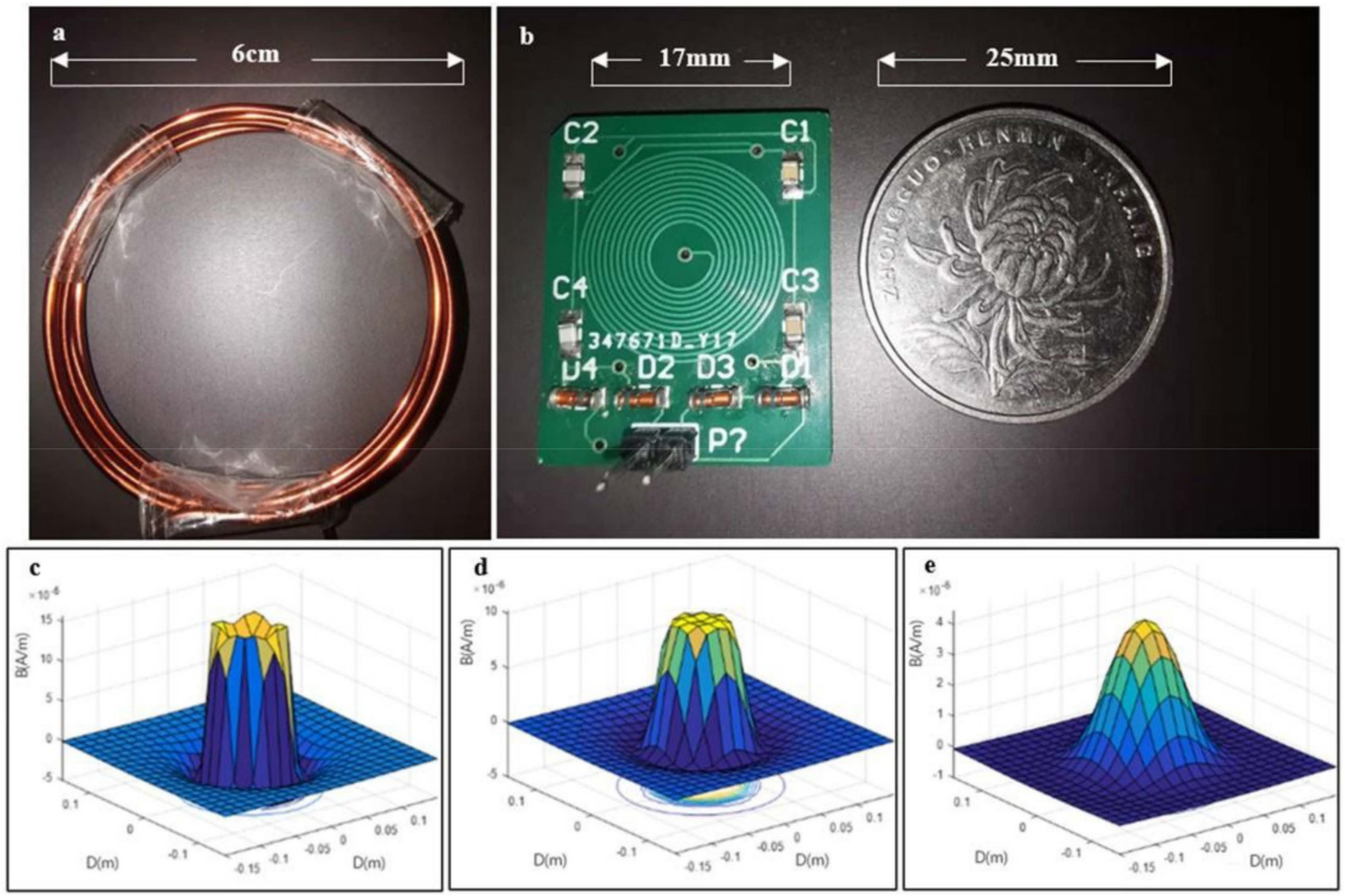
3.1. The Fabrication of Coil

Figure 6a,b show images of the TX coil and the RX coil, respectively.
The TX coil made of 1.5 mm-enameled wire is a cylindrical spiral coil, with a diameter of about 6 cm and 6 turns. The resistance of the TX coil is about 0.5 Ω, and the inductance is 3.68 μH. Because the TX coil is in the external circuit, the design has high flexibility and variability and can be manufactured in the laboratory according to actual needs. In this study, the TX coil is used for neural electrical stimulation in rats, and the coupling distance is generally 1–4 cm. Figure 6c–e shows the magnetic field stimulation results of the TX coil under MATLAB2018a.
The RX coil is a planar helical coil that is mounted on a four-layer FR-4 PCB of 20 mm × 25 mm in size with the receiving circuit. The outer diameter is about 1.7 cm. The diameter of wire and the spacing between the wires are about 0.25 mm. And the turn-number of the coil is twelve. The resonant capacitance of the receiving circuit is about 494 pF, and L3 = 5.37 μH is calculated from (9). The inductance is measured to be 5.59 μH using the UT612 LCR digital bridge. The actual resonant frequency f e = 3.03 MHz is calculated by the Formula (10).

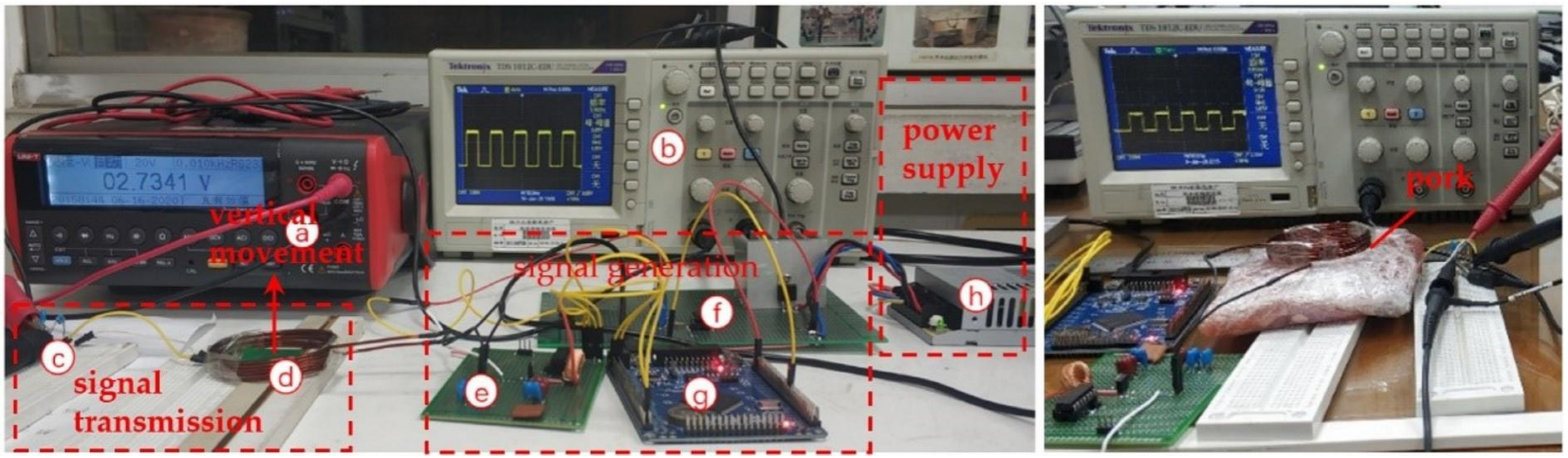
3.2. Signal Transmission Experiment

In the signal transmission process of this study, 1–20 Hz stimulation pulse (S1) and 3 MHz carrier pulse (S2) are generated by STM32. The gate drive signal Vg is modulated by these two signals using the AND gate. In 10 Hz, for example, Figure 7 shows the Vg signal generation process. After that, Vg generates high-frequency sinusoidal signals at L2 and L3 after oscillating through class E PA. The signal received on L3 passes through the rectifier to obtain the final stimulus signal S. As shown in Figure 8a–f, we get stimulus signals with different frequencies and duty cycles. Moreover, If the duty cycle of S is 1%, we can get the minimum pulse width of the stimulus signal. Figure 8g shows that the minimum pulse width is about 200 μs.

3.3. Output Performance Test

Figure 9 on the left shows the instrument and circuit used for the test experiment. Figure 9 on the right shows the power transmission experiment by using pork as the transmission medium.
We carried out an output capacity test, distance test, and medium test on the designed system, on the conditions that S1 = 3 MHz, S2 = 10 Hz, and duty cycle = 0.5.
First, at transmission distance D = 1 cm, the output capacity of the system is tested by changing the value of load impedance (100 Ω–2 kΩ) and VDD value (1 V, 2 V, 3 V). The voltage effective values under different loads and supply voltages are shown in Figure 10a. After that, the load impedance value (1 kΩ) was fixed to test the variation of the induced voltage with the transmission distance (Figure 10b). In the end, we repeated the experiment using 2 cm thick pork as the medium (Figure 10c).

4. Discussion

In this section, we describe the development and testing of a fully implantable wireless nerve stimulator for neuroelectrical stimulation rehabilitation experiments. The device is divided into an external circuit and an implantable part through a modular design that facilitates its miniaturization. In the process of device development, we used technologies including, but not limited to, single-chip microcomputer technology, signal modulation, and demodulation, wireless power supply, and integration/packaging. The system can realize flexible control of stimulus parameters to adapt to different application scenarios.
In this study, electrical stimulators were designed to target small animals such as rats. We designed the transmission distance between 1 and 4 cm, using an electromagnetic field frequency of 3 MHz. Through the approach of energy transmission, the system can meet the conditions required by neural electrical stimulation within the transmission distance. For the wireless energy transmission of electromagnetic waves, the overall trend is that the transmission efficiency increases with the increase of working frequency [32]. However, the increased working frequency can also cause the biological tissue to absorb too much energy, which can lead to tissue overheating and cause safety problems such as burns. Accordingly, we set 3 MHz as the operating frequency of the system.
Under these conditions, we discuss the experimental results as follows.
As shown in Figure 6, both transmitting and receiving coils can be manufactured in the laboratory with convenient features. The transmitting coil can be made at any time according to the desired inductance parameters. The outer diameter of the receiving coil is only 1.7 cm, which can meet the requirements of miniaturization and is implantable. Without changing parameters such as inductance, the diameter of the RX can be reduced by increasing the layer of coils, thereby reducing the size of the stimulator. However, more layers increase the resonant impedance of the coil. The diameter D0 is limited by the wire diameter w, the spacing between each turn b, and the number of turns N. Therefore, in our work, the RX coil is, at most, 4 layers with a minimum diameter of about 8 mm. The magnetic field simulation analysis of the transmitting coil shows that the magnetic field intensity around the transmitting coil is on the order of 10−6, which belongs to the safe range [33].
It can be seen from Figure 7 that the Vg signal will be directly used for switching control of the transistor, thus generating the oscillation wave patterns transmitting coil and sending them to the receiving circuit. Figure 8 shows that the minimum pulse width of S is about 200 μs. Duty cycle (1–50%), and frequency (1–20 Hz) can be changed within the set range, with an accuracy of 1% and 1 Hz, respectively. Simultaneously, the DAC function of the SCM controls the input voltage of the Class E PA in 0–5 V, and the adjustment accuracy is 0.7 mV. The stimulator can perform diverse and flexible work according to actual needs.
As can be seen from Figure 10a, when the resistance value of load impedance is large (>800 Ω), the induced voltage at both ends of the load is stable, and when the power supply is 3 V and the load impedance is 800 Ω, the effective value of the induced voltage is 4.3 V. It can be concluded that the peak voltage of square wave at this time is about 8.6 V, which is greater than the required stimulation voltage (5 V). Therefore, the wireless stimulator can effectively stimulate the nerves of rats. When the resistance value of the load impedance is small, the main reason for voltage reduction is that the wireless transmission power is not enough to meet the power consumption, resulting in a certain voltage drop.
Figure 10b shows that the induced voltage of the load varies significantly with the distance between the coils. Moreover, the further the distance, the lower the induced voltage value, which is because the coupling coefficient between the coils decreases as the distance is increased. In practical applications, if the receiving coil is embedded in rats and the transmitting coil is used for power transmission in vitro, the transmission distance is generally less than 2 cm. When the supply voltage is 3 V, the effective value of the induced voltage can reach 2.3 V at the transmission distance of 2 cm, that is to say, the voltage of the induced waveform can reach about 4.6 V. Additionally, the effective value is 0.7 V at the transmission distance of 4 cm, and effective electrical stimulation can be made.
In addition, the comparison between Figure 10b,c shows that the induced voltage of the load at the pork medium is very similar to that of air. The main reason for the difference is the interval error of the transceiver coil and the deviation of the axis of the transceiver coil.
However, some limitations should be noted. First, the induced voltage var obviously with distance, and the coupling distance is small. Second, the study did not consider the biocompatibility of the implants. Third, the power of the stimulus needs to be improved. Fourth, this study only designed stimulation tools without animal experiments. Finally, biodegradable preparation methods of inductors, capacitors, and other components have been realized [34,35], and biodegradable components can be used to avoid secondary trauma in future implanted circuit design.
In summary, we developed a wireless stimulator for rats. Given the size of the stimulator, it will be used primarily to stimulate the sciatic nerve in rats, with the spinal cord and brain also being potential targets. Both stainless steel electrodes [36] and Mg electrodes [5] can be used in experiments. It has been concluded that subcutaneous implantation of a 25-g (17.5 cm3) telemeter in a 170 g male rat does not harm animal health and well-being [37]. The stimulator we designed is much smaller, so the normal behavior of the rats will not be affected. Moreover, to minimize physical damage to tissue, a flexible receiver coil and flexible polyimide printed circuit board will be used in animal experiments. Koo, J. et al. [5] demonstrated that the flexible polyimide printed circuit can better fit neural tissue, and it can also provide a stable, low-profile, non-invasive means of facilitating chronic neural stimulation.

5. Conclusions

In this paper, a wireless stimulator is designed and tested for electrical stimulation. The stimulator consists of a transmitting circuit and an implanted circuit. At a distance of 1–4 cm and a frequency of 3 MHz, the magnetically coupled resonant wireless power transfer (MCR-WPT) technology is used to transmit energy. The transmitter uses STM32F103ZET6 SCM as the signal control part and the Class E PA as the power amplification part. The receiver is a circuit built with a passive device that can be implanted in rats. After signal transmission experiments and output performance tests, the stimulator can output a single-phase pulse signal with variable parameters, and the power is about 25 mW. The stimulation frequency varied from 1 Hz to 20 Hz, the duty cycle varied from 1 to 50%, and the minimum pulse width was 200 μs. The input voltage of the stimulator is variable from 0 to 5 V. When the input voltage is 3 V and the duty cycle is 0.5, the effective value reaches 4.3 V, 2.3 V, and 0.7 V at the transmission distance of 1, 2, and 4 cm, respectively. Therefore, the stimulator can perform low frequency, safe and controllable wireless stimulation over a short distance.

Author Contributions

Project administration, Y.Z.; methodology, T.P.; software, T.P.; supervision, Y.Z.; writing—original draft preparation, T.P.; Writing—review and editing, Y.Z. All authors have read and agreed to the published version of the manuscript.

Funding

This research received no external funding.

Institutional Review Board Statement

Not applicable.

Informed Consent Statement

Not applicable.

Data Availability Statement

Not applicable.

Acknowledgments

This research did not receive any specific grant from funding agencies in the public, commercial, or not-for-profit sectors.

Conflicts of Interest

The authors declare no conflict of interest.

References

  1. Noble, J.; Munro, C.A.; Prasad, V.S.; Midha, R. Analysis of upper and lower extremity peripheral nerve injuries in a population of patients with multiple injuries. Trauma 1998, 45, 116–122. [Google Scholar] [CrossRef] [PubMed]
  2. Hadlock, T.A.; Sundback, C.A.; Hunter, D.A.; Vacanti, J.P.; Cheney, M.L. A new artificial nerve graft containing rolled Schwann cell monolayers. Microsurgery 2001, 21, 96–101. [Google Scholar] [CrossRef] [PubMed]
  3. Sahenk, Z.; Nagaraja, H.N.; McCracken, B.S.; King, W.M.; Freimer, M.L.; Cedarbaum, J.M.; Mendell, J.R. NT–3 promotes nerve regeneration and sensory improvement in CMT1A mouse models and in patients. J. Neurol. 2005, 65, 681–689. [Google Scholar] [CrossRef]
  4. Mohammad, J.; Shenaq, J.; Rabinovsky, E.; Shenaq, S. Modulation of peripheral nerve regeneration: A tissue-engineering approach. The role of amnion tube nerve conduit across a 1-centimeter nerve gap. Plast. Reconstr. Surg. 2000, 105, 660–666. [Google Scholar] [CrossRef] [PubMed]
  5. Koo, J.; MacEwan, M.R.; Kang, S.K.; Won, S.M.; Stephen, M.; Gamble, P.; Xie, Z.Q.; Yan, Y.; Chen, Y.Y.; Shin, J.; et al. Wireless bioresorbable electronic system enables sustained nonpharmacological neurodegenerative therapy. Nat. Med. 2018, 24, 1830. [Google Scholar] [CrossRef] [PubMed]
  6. Adkins-Muir, D.L.; Jones, T.A. Cortical electrical stimulation combined with rehabilitative training: Enhanced functional recovery and dendritic plasticity following focal cortical ischemia in rats. Neurol Res. 2003, 25, 780–788. [Google Scholar] [CrossRef]
  7. Berényi, A.; Belluscio, M.; Mao, D.; Buzsáki, G. Closed-loop control of epilepsy by transcranial electrical stimulation. Science 2012, 337, 735–737. [Google Scholar] [CrossRef] [Green Version]
  8. Calancie, B.; Harris, W.; Broton, J.G.; Alexeeva, N.; Green, B.A. “Threshold-level” multipulse transcranial electrical stimulation of motor cortex for intraoperative monitoring of spinal motor tracts: Description of method afnd comparison to somatosensory evoked potential monitoring. J. Neurosurg. 1998, 88, 457–470. [Google Scholar] [CrossRef] [Green Version]
  9. Kozák, G.; Földi, T.; Berényi, A. Chronic Transcranial Electrical Stimulation and Intracortical Recording in rats. JOVE 2018, 135, e56669. [Google Scholar] [CrossRef] [Green Version]
  10. Matsuyama, N.; Uwano, T.; Hori, E.; Ono, T.; Nishijo, H. Reward contingency modulates neuronal activity in rat septal nuclei during elemental and configural association tasks. Front. Behav. Neuro. 2011, 5, 26. [Google Scholar] [CrossRef] [Green Version]
  11. Chen, X.; Xu, K.; Ye, S.; Guo, S.; Zheng, X. A remote constant current stimulator designed for rat-robot navigation. In Proceedings of the 2013 35th Annual International Conference of the IEEE Engineering in Medicine and Biology Society (EMBC), Osaka, Japan, 3–7 July 2013; pp. 2168–2171. [Google Scholar]
  12. Xu, S.; Talwar, S.K.; Hawley, E.S.; Li, L.; Chapin, J.K. A multi-channel telemetry system for brain micro stimulation in freely roaming animals. J. Neuralsci. Methods 2004, 133, 57–63. [Google Scholar] [CrossRef] [PubMed]
  13. Yang, J.; Huai, R.; Wang, H.; Lv, C.; Su, X. A robo-pigeon based on an innovative multi-mode telestimulation system. Bio-Med. Mater. Eng. 2015, 26, S357–S363. [Google Scholar] [CrossRef] [PubMed] [Green Version]
  14. Ye, X.S.; Wang, P.; Liu, J.; Zhang, S.; Jiang, J.; Wang, Q.; Chen, W.; Zheng, X. A portable telemetry system for brain stimulation and neuronal activity recording in freely behaving small animals. J. Neurosci. Methods 2008, 174, 186–193. [Google Scholar] [CrossRef] [PubMed]
  15. Yun, S.; Kon, C.S.; Jeong, J.; Seo, J.; Ahn, S.H.; Choi, G.J.; Shim, S.; Shin, J.; Jung, H.H.; Chang, J.W.; et al. Remote-Controlled Fully Implantable Neural Stimulator for Freely Moving Small Animal. Electronics 2019, 8, 706. [Google Scholar] [CrossRef] [Green Version]
  16. Millard, R.E.; Shepherd, R.K. A fully implantable stimulator for use in small laboratory animals. J. Neuralsci. Methods 2007, 166, 168–177. [Google Scholar] [CrossRef] [Green Version]
  17. Perry, D.; Grayden, D.; Shepherd, R.; Fallon, J. A fully implantable rodent neural stimulator. J. Neural Eng. 2012, 9, 014001. [Google Scholar] [CrossRef] [Green Version]
  18. Nguyen, H.D.; Tan, P.Z.; Sato, H.; Vo-Doan, T.T. Sideways Walking Control of a Cyborg Beetle. IEEE Trans. Med. Robot. Bionics 2020, 2, 331–337. [Google Scholar] [CrossRef]
  19. Vo-Doan, T.T.; Li, Y.; Cao, F.; Sato, H. Cyborg beetle: Thrust control of free flying beetle via a miniature wireless neuromuscular stimulator. In Proceedings of the 2015 28th IEEE International Conference on Micro Electro Mechanical Systems (MEMS), Estoril, Portugal, 18–22 January 2015; pp. 1048–1050. [Google Scholar] [CrossRef]
  20. Sanchez, C.J.; Chiu, C.-W.; Zhou, Y.; González, J.M.; Vinson, S.B.; Liang, H. Locomotion control of hybrid cockroach robots. J. R. Soc. Interface 2015, 12, 20141363. [Google Scholar] [CrossRef]
  21. Dirafzoon, A.; Latif, T.; Gong, F.; Sichitiu, M.; Bozkurt, A.; Lobaton, E. Biobotic motion and behavior analysis in response to directional neurostimulation. In Proceedings of the 2017 IEEE International Conference on Acoustics, Speech and Signal Processing (ICASSP), New Orleans, LA, USA, 5–9 March 2017; pp. 2457–2461. [Google Scholar] [CrossRef]
  22. Ho, J.S.; Yeh, A.J.; Neofytou, E.; Kim, S.; Tanabe, Y.; Patlolla, B.; Beygui, R.E.; Poon, A.S.Y. Wireless power transfer to deep-tissue microimplants. Proc. Natl. Acad. Sci. USA 2014, 111, 7974–7979. [Google Scholar] [CrossRef] [Green Version]
  23. Montgomery, K.L.; Yeh, A.J.; Ho, J.S.; Tsao, V.; Mohan Iyer, S.; Grosenick, L.; Ferenczi, E.A.; Tanabe, Y.; Deisseroth, K.; Delp, S.L.; et al. Wirelessly powered, fully internal optogenetics for brain, spinal and peripheral circuits in mice. Nat. Methods 2015, 12, 969–974. [Google Scholar] [CrossRef] [Green Version]
  24. Agarwal, K.; Jegadeesan, R.; Guo, Y.-X.; Thakor, N.V. Wireless Power Transfer Strategies for Implantable Bioelectronics. IEEE Rev. Biomed. Eng. 2017, 10, 136–161. [Google Scholar] [CrossRef] [PubMed]
  25. Lu, M.C.; Ho, C.Y.; Hsu, S.F.; Lee, H.C.; Lin, J.H.; Yao, C.H.; Chen, Y.S. Effects of Electrical Stimulation at Different Frequencies on Regeneration of Transected Peripheral Nerve. Neur. Neural Repair 2007, 22, 367–373. [Google Scholar] [CrossRef] [PubMed]
  26. Chen, Y.-S.; Hu, C.-L.; Hsieh, C.-L.; Lin, J.-G.; Tsai, C.-C.; Chen, T.-H.; Yao, C.-H. Effects of percutaneous electrical stimulation on peripheral nerve regeneration using silicone rubber chambers. J. Biomed. Mater. Res. 2001, 57, 541–549. [Google Scholar] [CrossRef]
  27. Zhou, H.; Xu, Q.; He, J.P.; Ren, H.K.; Zhou, H.L.; Zheng, K.J. A fully implanted programmable stimulator based on wireless communication for epidural spinal cord stimulation in rats. J. Neurosci. Methods 2012, 204, 341–348. [Google Scholar] [CrossRef]
  28. Kang, S.K.; Murphy, R.K.J.; Hwang, S.W.; Lee, S.M.; Harburg, D.V.; Krueger, N.A.; Shin, J.H.; Gamble, P.; Cheng, H.Y.; Yu, S.; et al. Bioresorbable silicon electronic sensors for the brain. Nature. 2016, 530, 71–76. [Google Scholar] [CrossRef]
  29. Ahmadi, M.M.; Salehi-Sirzar, M. A Self-Tuned Class-E Power Oscillator. IEEE Trans. Power Electr. 2019, 34, 4434–4449. [Google Scholar] [CrossRef]
  30. Kazimierczuk, M.K.; Krizhanovski, V.G.; Rassokhina, J.V.; Chernov, D.V. Class-E MOSFET tuned power oscillator design procedure. IEEE Trans. Circuits Syst. I Regul. 2005, 52, 1138–1147. [Google Scholar] [CrossRef]
  31. Waters, B.H.; Mahoney, B.J.; Lee, G.; Smith, J.R. Optimal coil size ratios for wireless power transfer applications. In Proceedings of the 2014 IEEE International Symposium on Circuits and Systems (ISCAS), Melbourne, Australia, 1–5 June 2014; pp. 2045–2048. [Google Scholar] [CrossRef]
  32. Shadid, R.; Noghanian, S. A literature survey on wireless power transfer for biomedical devices. Int. J. Antennas Propag. 2018, 2018, 4382841. [Google Scholar] [CrossRef] [Green Version]
  33. IEEE Standards Coordinating Committee. IEEE Standard for Safety Levels with Respect to Human Exposure to Radio Frequency Electromagnetic Fields, 3 kHz to 300 GHz; IEEE Std C95.1-2005 (Revision of IEEE Std C95.1-1991); IEEE: Manhattan, NY, USA, 2005; pp. 1–238. [Google Scholar] [CrossRef]
  34. Cheng, H.Y.; Vepachedu, V. Recent development of transient electronics. Theor. Appl. Mech. Lett. 2016, 6, 21–31. [Google Scholar] [CrossRef] [Green Version]
  35. Hwang, S.W.; Huang, X.; Seo, J.H.; Song, J.K.; Stanley, K.; Hage-Ali, S.; Chung, H.J.; Tao, H.; Omenetto, F.G.; Ma, Z.Q. Materials for Bioresorbable Radio Frequency Electronics. Adv. Mater. 2013, 25, 3526–3531. [Google Scholar] [CrossRef]
  36. Lyu, H.; Wang, J.; La, J.-H.; Chung, J.M.; Babakhani, A. An Energy-Efficient Wirelessly Powered Millimeter-Scale Neurostimulator Implant Based on Systematic Codesign of an Inductive Loop Antenna and a Custom Rectifier. IEEE Trans. Biomed. Circuits Syst. 2018, 12, 1131–1143. [Google Scholar] [CrossRef] [PubMed]
  37. Moran, M.M.; Roy, R.R.; Wade, C.E.; Corbin, B.J.; Grindeland, R.E. Size constraints of telemeters in rats. J. Appl. Physiol. 1998, 85, 1564–1571. [Google Scholar] [CrossRef] [PubMed]
Figure 1. A fully implantable electrical nerve stimulator: the implanted circuit with a rectifier and receive coil (TX), the transmit coil (RX) under the terrarium supplies energy by using magnetically coupled resonant wireless power transfer (MCR-WPT), the external circuit is used to generate signals.
Electronics 11 01104 g001
Figure 2. The system overview of the wireless stimulation system.
Electronics 11 01104 g002
Figure 3. The cross-section of the planar spiral coil. The Di is the inner diameter; the req is the equivalent radius of the coil; the hs is the width of the coil.
Electronics 11 01104 g003
Figure 4. (a) The control circuit diagram of DAC output. The input is the DAC voltage of 0–3.3 V. The output voltage is 0–5 V; (b) The π type impedance matching network.
Electronics 11 01104 g004
Figure 5. (a) The relationship between the DAC setting values and the output voltages; (b) The signal transmission process.
Electronics 11 01104 g005
Figure 6. The fabrication of coils: (a) The TX coil; (b) The RX coil and receiving circuit on the left; (c) The magnetic field stimulation of TX coil on the plane with transmission distance D = 1 cm; (d) D = 2 cm; (e) D = 5 cm.
Electronics 11 01104 g006
Figure 7. The modulation of the Vg signal (a) the high-frequency carrier pulse S2 = 3 MHz; (b) the low-frequency stimulation pulse S1 = 10 Hz; (c) the Vg signal.
Electronics 11 01104 g007
Figure 8. The stimulus signal of different parameters: (ac) the stimulus signal of different frequencies: 20 Hz, 10 Hz, 5 Hz; (df) the stimulus signal of different duty cycles:10%, 20%, 40%; (g) the minimum pulse width is about 200 μs when the duty cycle is 0.01.
Electronics 11 01104 g008
Figure 9. The experiments of output performance test with different media: air (left) and pork (right). The testing instruments used are multimeter (UNI-T UT805A, a), oscilloscope (Tektronix TDS 1012C-EDU, b). In the picture, the c is the simulated load impedance; the d represents for the TX coil and the RX coil and they move vertically in a coaxial way; the e is the Class E PA circuit; the f is LM317 controllable constant-voltage circuit; the g is STM32 microcontroller; and the h is switching power supply to make the LM317 work.
Electronics 11 01104 g009
Figure 10. The results of output performance test: (a) the voltage effective values under different loads and supply voltages; (b) the transmission distance test in the air; (c) the transmission distance test with the 2 cm thick pork.
Electronics 11 01104 g010
Table 1. The comparisons between existing research results with our work in stimulus parameters.
[7][12][17][27]This Work
WaveformIrregularSingle-phase pulseDual-phase pulseIrregularSingle-phase pulse
Frequency0, 10, 20, 80 Hz100 Hz60 Hz1–255 Hz (1-Hz step)1–20 Hz (1-Hz step)
Duty cycleN/A50%1.2%N/A1–50%
Output voltage11 V9 VN/A0.1–10 V0–5 V
Current0–5 mA15 mA0.6 mA1 mA5 mA
Average power30 mW67.5 mWN/A10 mW25 mW
Table 2. The value of the circuit component.
ItemsValuesItemsValues
C11.62 nFL1200 μH
C20.87 nFL23.64 μH
C3494 pFL35.59 μH
C41.63 nFL40.88 μH
C51.37 nFR10 Ω
Table 3. The parameter design of the PWM output.
TIM_PeriodTIM_Prescalerf (Hz)Note
12303 × 106carrier pulse
2720050020stimulation pulse
37200100010stimulation pulse
4720020005stimulation pulse
Publisher’s Note: MDPI stays neutral with regard to jurisdictional claims in published maps and institutional affiliations.

