1. Introduction
The power combining of high-power microwave oscillators is a promising way to achieve ultra-high power levels [
1]. Coherent power summation of relativistic magnetrons [
2,
3,
4,
5,
6,
7], vircators [
8,
9,
10,
11], and relativistic backward-wave oscillators [
12,
13,
14] at up-to-multi-gigawatt power levels has been demonstrated. Recently, the power combining of gyrotrons has attracted a special interest since arrays of high-power gyrotrons are of great importance for electron-cyclotron-resonance plasma heating [
15] and certain other applications [
16]. A critical issue for the coherent power summation is phase and frequency locking. Both injection locking [
4,
6,
10,
14,
17,
18,
19] and peer-to-peer locking [
2,
3,
4,
7,
8,
9,
20,
21] techniques have been widely studied. The injection locking [
22,
23] and peer-to-peer [
24] locking of gyrotrons is currently a subject of active investigation.
Since at microwave frequencies, the distance between coupled oscillators significantly exceeds the operating wavelength, the delay of the signal propagating between the oscillators should be taken into account, which greatly increases the complexity of the system. In [
25,
26], we studied a simple model of two delay-coupled oscillators in the form of two coupled delay-differential equations (DDEs). Due to the delay, the coupling signal acquires a phase shift that strongly affects the locking process. We presented the detailed theoretical analysis showing that, depending on the phase shift, the system can demonstrate the behavior typical for either dissipative (diffusive) or conservative (reactive) coupling. In the first case, the oscillators may lock either in-phase or anti-phase, while in the second case, both in phase and anti-phase locking may occur, i.e., the bistability of the phase-locked states appears.
In [
27,
28], we proposed a simple model, which extends the analysis presented in [
25,
26] to the peer-to-peer locking of gyrotrons. This model allows for a comprehensive theoretical analysis of peer-to-peer locking regimes, including the use of modern software tools for the bifurcation analysis of nonlinear dynamical systems. On the other hand, it can predict the main characteristics, such as power, efficiency, and oscillation frequency, with the same accuracy as the nonstationary theory of a gyrotron with a fixed RF field profile.
It is well-known that the maximal interaction efficiency of high-power gyrotrons is usually attained in the regime of hard self-excitation. This significantly complicates the pattern of phase locking. In this article, we study the peer-to-peer locking of gyrotrons operating at the point of maximal efficiency, i.e., in the hard excitation mode. In
Section 2, we briefly review the basic equations of the gyrotron with the fixed profile of the RF field, as well as the DDE model of two coupled gyrotrons. In
Section 3, we present the results of theoretical and numerical analysis. First, we study the peer-to-peer locking in the phase approximation assuming that the oscillation amplitudes of the weakly coupled gyrotrons are close to those of the free-running gyrotrons. We derive the modified Adler’s equation, which allows for an analysis of the phase-locked modes in different cases. Then, we present the results of a more relevant analysis not limited to the case of weak coupling. We examine the stability of the in-phase and anti-phase synchronous states and reveal the complicated pattern of the phase-locking domains on the frequency mismatch—coupling strength parameter plane.
2. Model and Basic Equations
We will proceed from the well-known equations of the gyrotron theory with a fixed RF profile (see, e.g., [
29]). Considering the interactions at the fundamental cyclotron harmonic,
, where
and
are the oscillation frequency and cyclotron frequency, respectively, the equation of the electron’s motion reads:
In (1),
is the dimensionless transverse electron momentum,
is the dimensionless complex amplitude of the RF field,
is the dimensionless axial coordinate,
,
,
and
are the initial axial and transversal velocities, respectively, and
is the cyclotron resonance mismatch. The function
describing the field profile in the resonator is approximated by the Gaussian function:
where
is the normalized length of the interaction space. Equation (1) is solved with the boundary conditions:
where the initial phases
are distributed uniformly over the interval
.
To find the slow-flow amplitude
, one should solve the excitation equation:
here
is the normalized time,
is the Q-factor of the resonator,
is the complex electronic susceptibility, and
is the normalized beam current parameter. In (6),
and
are the electron charge and rest mass, respectively,
is the dc beam current,
H/m is the magnetic constant,
is the relativistic mass factor,
is the wave norm,
is the normalized length of the resonator,
is the factor of beam coupling with the operating TE
mn mode,
is the
mth-order Bessel function of the first kind,
is the
nth positive root of the equation
, and
and
are the radii of the electron beam and the waveguide, respectively.
Solving the equations of motion (1), one can evaluate the real (active)
and imaginary (reactive)
parts of the electronic susceptibility as functions of the amplitude and cyclotron resonance mismatch.
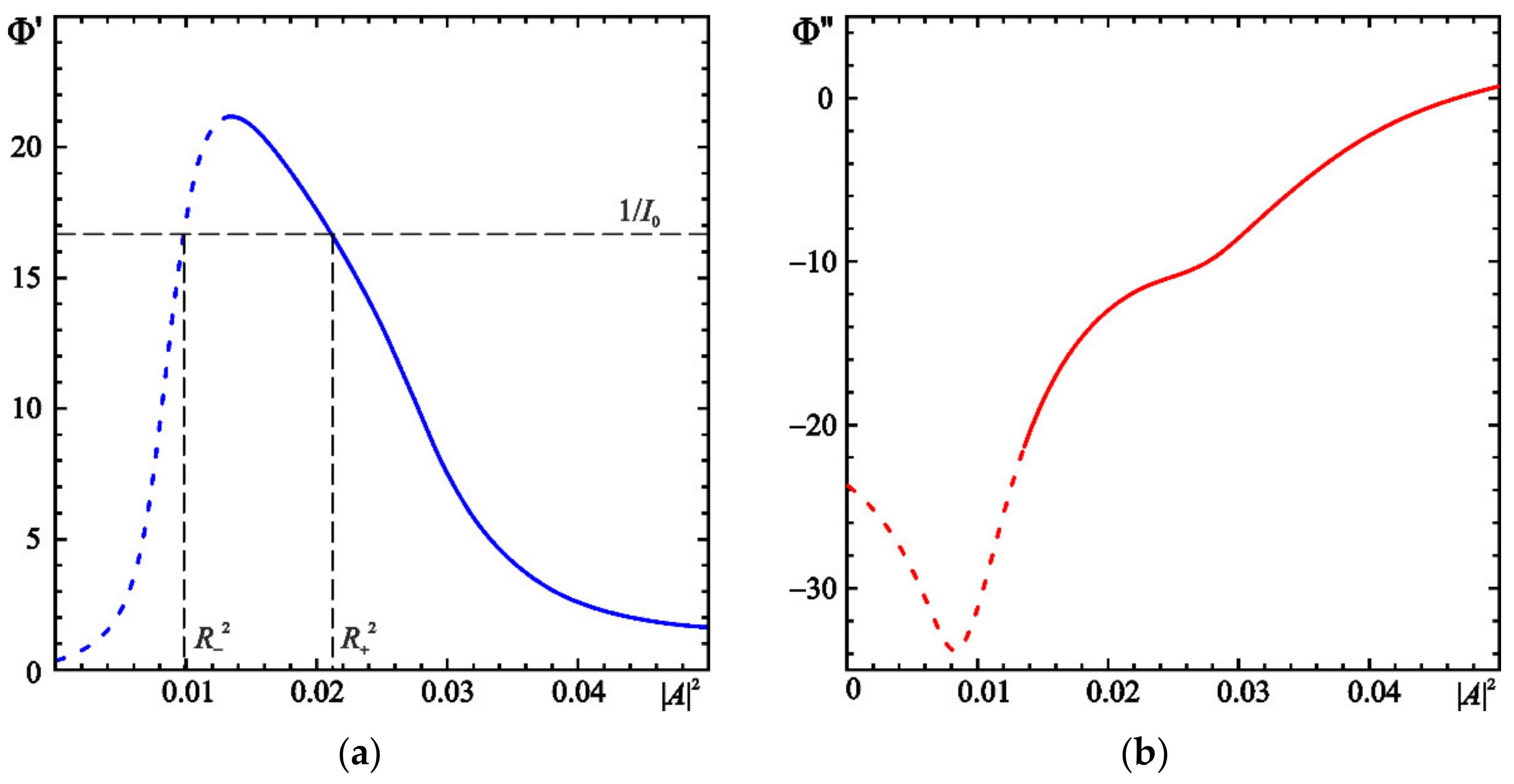
Figure 1 shows
and
calculated at
and
.
In the regime of steady-state single-frequency oscillation
, where
,
, and
are oscillation amplitude, frequency, and phase, respectively. From (4) it follows that:
As is shown in
Figure 1a, there exist two steady-state solutions to (7):
and
. From (4), one can easily find that
is unstable, while
is stable. In
Figure 1, stable and unstable states are shown with solid and dotted lines, respectively. In addition, there exists the trivial solution
, which is also stable. This confirms that, at the chosen parameters, the gyrotron operates in the hard-excitation mode.
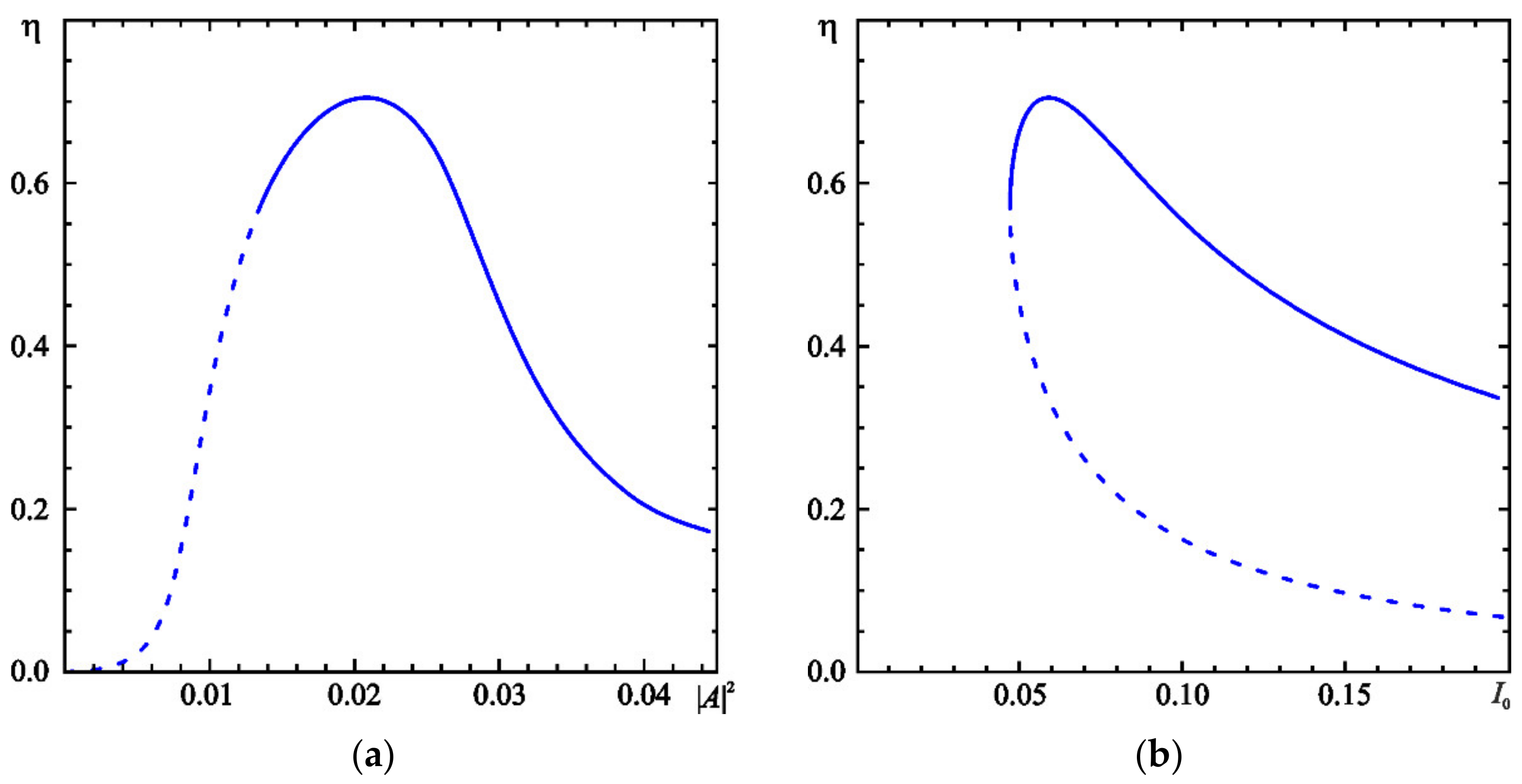
In the steady-state regime, the orbital electronic efficiency is [
27,
28,
29]:
The plots of efficiency versus
and versus
are presented in
Figure 2a,b, respectively. The efficiency attains its maximal value
at
. The corresponding value of the amplitude is
.
For the analysis of peer-to-peer locking, consider a system of two coupled gyrotrons, which are assumed identical, except for small detuning of the eigenfrequencies, i.e.,
, where
and the subscripts 1 and 2 refer to the first and the second gyrotron, respectively. In that case, instead of (4) we obtain a system of two coupled DDEs [
27,
28]:
In (10),
is the coupling strength, which is determined by the ratio of the input and output powers [
2,
3,
4,
5,
6,
7,
8];
is the normalized delay time; and
is the phase advance of the coupling signal. The delay time is
, where
is the distance between the gyrotrons.
3. Peer-to-Peer Locking Analysis: Case of Small Delay
3.1. Modes of Phase Locking
Following [
25,
26,
27,
28], consider the situation when the normalized delay time is small, i.e.,
. In that case, we can neglect the delay in the right-hand sides of (10), i.e.,
, and obtain the system of ordinary differential equations (ODEs):
Note that this assumption does not mean that we completely neglect the effect of delay because the phase advance is determined by the delay time.
It is convenient to divide the complex Equation (11) into equations for real amplitudes
and phases
. Substituting
into (11), after some calculations we arrive at the third-order ODE system:
where
,
,
.
Let us briefly discuss the possible steady-state solutions of (12), which describe the regimes of the synchronous oscillations of the two coupled oscillators. For a steady-state solution, (12) yields:
For simplicity, assume that the coupling is weak, i.e., . In such a situation, the values of are close to the steady state solutions of the uncoupled equations, i.e., to or to 0. Thus, the steady-state solutions can be classified as follows:
;
;
, and vice versa;
, and vice versa;
, and vice versa;
Solution 1 is of the most interest since it corresponds to the regimes of peer-to-peer locking. Solution 4 describes the situation when one gyrotron suppresses the oscillation of the second one. Solutions 2, 3, and 5 are always unstable, since is the unstable steady state an uncoupled gyrotron.
In addition, (12) has zero solution which, at least at weak coupling, is stable.
3.2. Generalized Adler’s Equation
A simple method of analysis of the phase locking phenomena is the so-called phase approximation when it is assumed that the weak coupling does not significantly change oscillation amplitudes of the two coupled systems and they remain nearly the same as for the uncoupled oscillators. Assuming
, the third equation of (12) yields:
This equation proposed by Adler [
30] was widely used for the analysis of locking phenomena, see, e.g., [
2,
4,
5,
19,
31,
32]. However, in the case of delayed coupling, (14) cannot provide the complete picture of phase locking. Evidently, (14) is not valid at
when
. This situation requires more rigorous analysis [
25].
Following [
25], let us seek the solution
, where
. By substituting this into (13) and expanding
up to the second-order terms, we obtain the approximate solution:
From (15) we find:
and substitute (16) in the third equation of (12). In addition,
should be expanded up to the second-order terms. As a result, we obtain the generalized Adler’s equation:
The terms proportional to
and to
on the right-hand side of (17) represent dissipative (diffusive) and conservative (reactive) coupling, respectively [
25]. In the phase-locked state, when
, we obtain:
From this equation, one can find the locking bandwidth. The edge of the locking region can be found from the condition
(see, e.g., [
25]), which yields:
Equations (18) and (19) allow the domains of stability of the phase-locked states on the -plane to be plotted.
A special attention should be paid to two particular cases. The first is the case of purely dissipative coupling, which occurs when:
In that case, from (18) we obtain:
Depending on
, the oscillators are locked either in-phase or anti-phase. Indeed, at
,
is either 0, or
. Phase locking occurs when the frequency mismatch
, where:
is the locking bandwidth.
The second case is a purely conservative coupling, which occurs when:
Instead of (21), the equation for the locked phase is:
and the locking bandwidth is given by:
The locking bandwidth is proportional to , in contrast with the case of dissipative coupling, when it is proportional to .
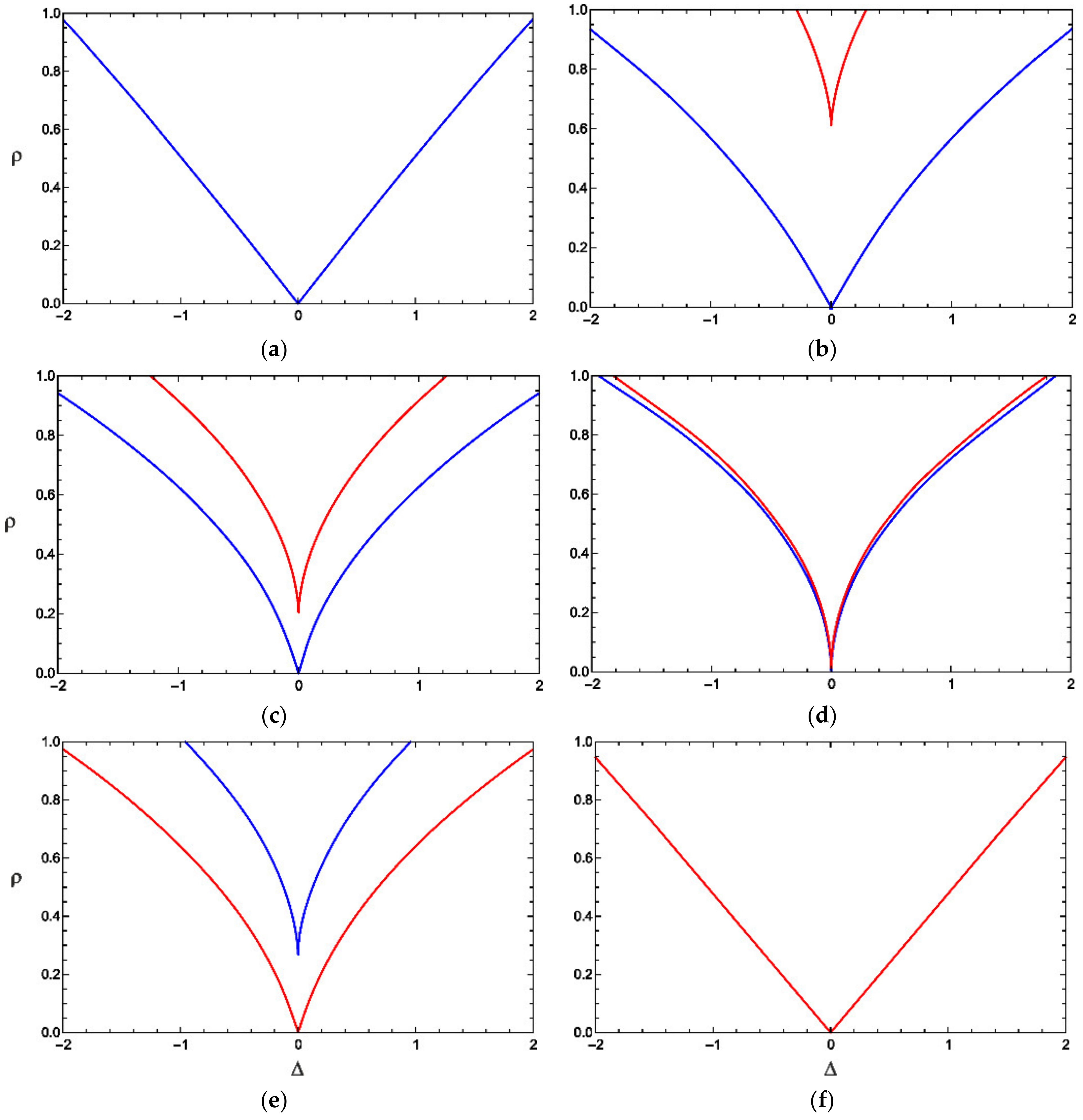
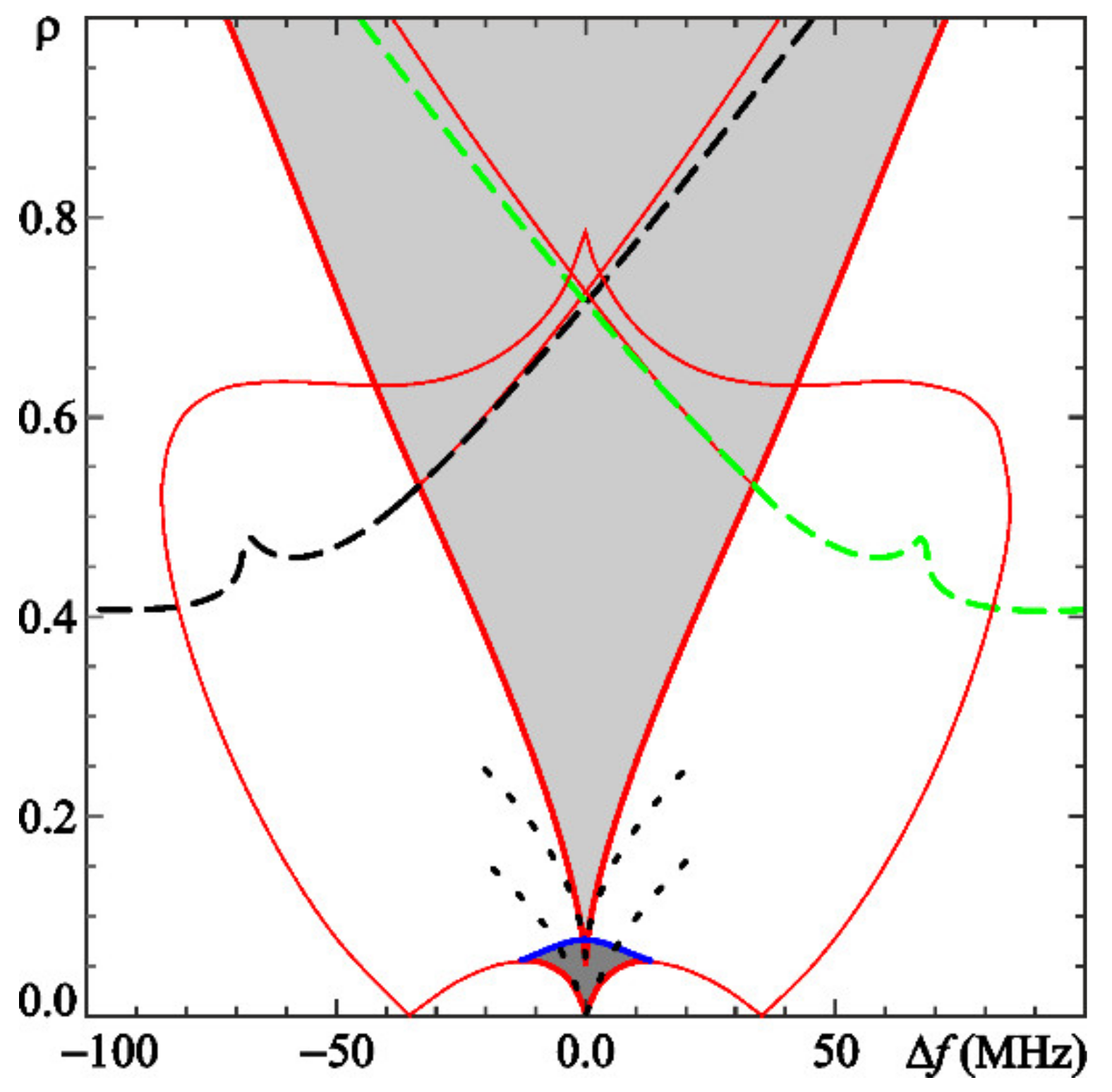
In
Figure 3, phase-locking domains on the
-plane are plotted at
and different values of
. In the case of dissipative coupling (
Figure 3a), only in-phase locking is possible. The boundary on the
-plane has the classical shape of Arnold’s tongue [
31,
32]. With the increase in
, the locking bandwidth reduces and the domain of the anti-phase locking appears (
Figure 3b). Then, the boundary of the anti-phase mode shifts downwards (
Figure 3c). At
, the coupling becomes purely conservative. The boundaries of the in-phase and anti-phase modes merge (
Figure 3d). Inside the locking region, the oscillators may lock either in-phase or anti-phase, i.e., there appears to be phase bistability [
25]. The classic Adler’s equation (14) fails to describe this situation. At
the anti-phase mode dominates. The domain of in-phase locking shifts upward and vanishes (
Figure 3e,f).
3.3. Structure of Locking Domains
The generalized Adler’s equation provides only a qualitative picture of phase locking since, strictly speaking, it is valid only in the case of weak coupling,
. For a more rigorous analysis, we investigate the third-order ODE system (12) employing the XPPAUT public-domain software [
33] that is a powerful tool for bifurcation analysis of ODEs. In [
26], we applied XPPAUT for a detailed analysis of peer-to-peer locking of two coupled Landau–Stuart oscillators with a weak cubic nonlinearity. We revealed a complicated structure of locking domains on the
-plane and intriguing scenarios of transition to the phase-locked modes. The behavior of two coupled gyrotrons with a strong nonlinearity operating in the hard-excitation mode is even more complicated. In particular, this is due to presence of a large number of steady-state oscillation modes, as discussed in
Section 3.1.
As mentioned above, for a gyrotron with a Gaussian profile of the RF field at
and
, the orbital efficiency reaches its maximal value
when the amplitude of the stable steady-state oscillation is
. This value is attained when the beam’s current parameter is set to
. However, in the system of two coupled gyrotrons the amplitude, will increase (in case of in-phase locking) or decrease (in case of anti-phase locking). This causes a decrease in efficiency [
28].
Therefore, it is beneficial to slightly reduce the current. With the increase in coupling, the amplitudes will increase and approach the optimal value at which the maximal efficiency is provided [
28]. So, we set the current parameter to
. At that value,
and the efficiency of the uncoupled gyrotron is
.
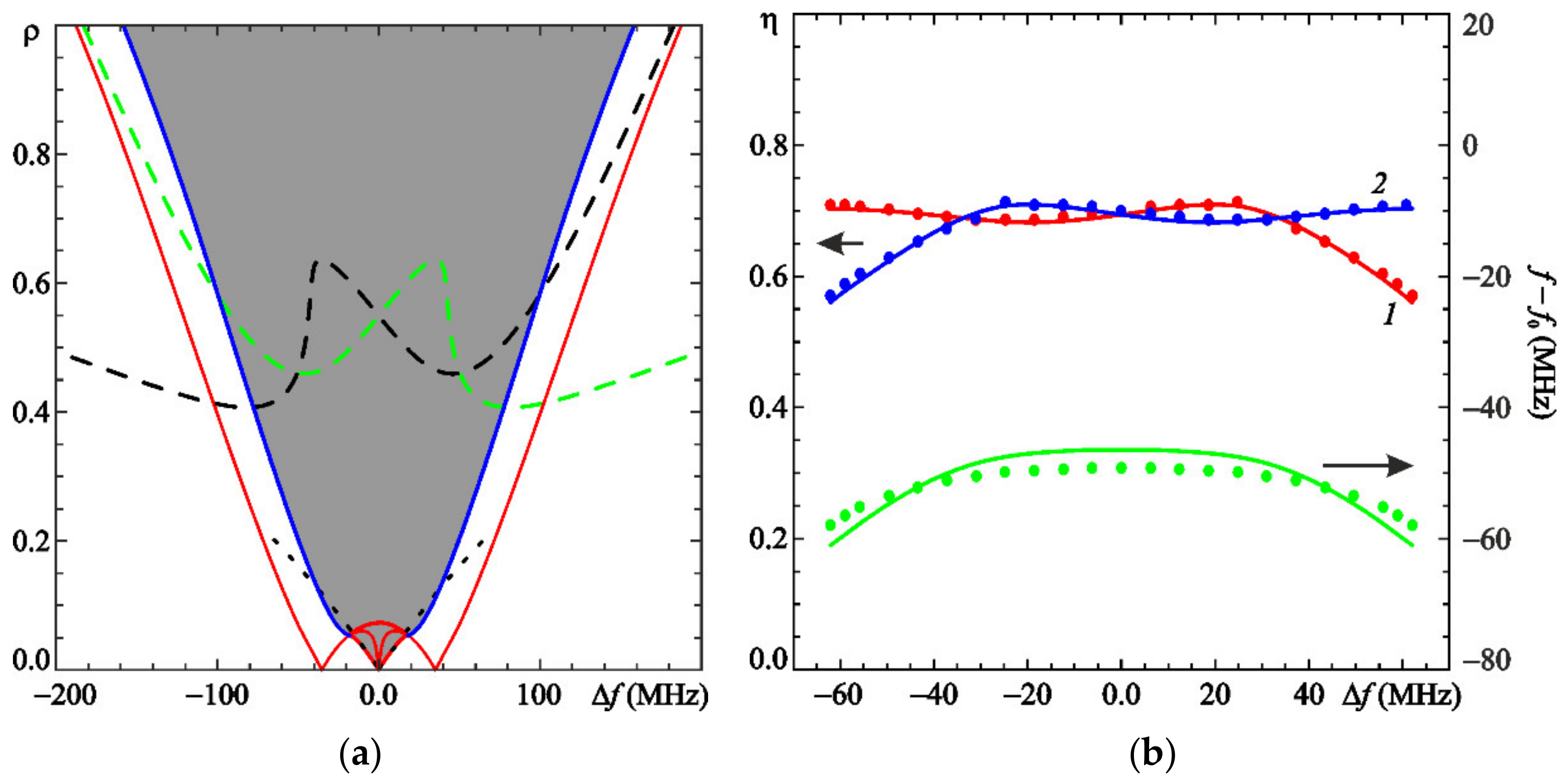
First, we considered the case
when the coupling is dissipative. In
Figure 4a, the domain of phase locking on the
-plane is shown, where
is non-normalized frequency mismatch. To evaluate
, we assume that the cold cavity resonant frequency and Q-factor are
GHz and
, respectively. These values are typical for MW-power fusion gyrotrons [
15].
In
Figure 4a, the domain of in-phase locking is shaded. It is bounded by the lines of saddle-node and Andronov–Hopf bifurcations. The boundary of the saddle-node bifurcation is close to the locking boundary obtained via the generalized Adler’s Equation (17) shown with dotted line. However, this approximation is valid only in the domain of very small
.
In the locking regime, the amplitudes of the first and second gyrotrons are close. In addition, there exist regimes in which the first gyrotron suppresses the second one and vice versa (
Section 3.1). Accordingly, the amplitudes are strongly different. These regimes are stable below the dashed lines shown in
Figure 4a.
In
Figure 4b, the orbital efficiencies of the first and second gyrotron calculated at the coupling strength
are plotted. Despite the reduced current, the coupling compensates the decrease in efficiency. In most of the locking band, the efficiency is close to the maximal value
. A similar behavior was reported in [
28].
Figure 5 illustrates the situation of conservative coupling. As predicted in
Section 3.2, both in-phase and anti-phase locking is possible. Similar to
Figure 4a, in the domain of small
, the stability boundaries are in reasonable agreement with the generalized Adler’s equation. The locking bandwidth is much narrower than in the case of dissipative coupling. Thus, the case of conservative coupling is not favorable for peer-to-peer locking. On the other hand, it is possible to realize fast stepwise frequency modulation by controllable switching between the two modes, as suggested in [
28].
4. Numerical Simulations in the Case of Arbitrary Delay
The results obtained in the small-delay approximation were verified by numerical integration of the DDEs (10). In the simulations, the normalized delay time was set to
, which corresponds to nearly a 2 m distance between the gyrotrons [
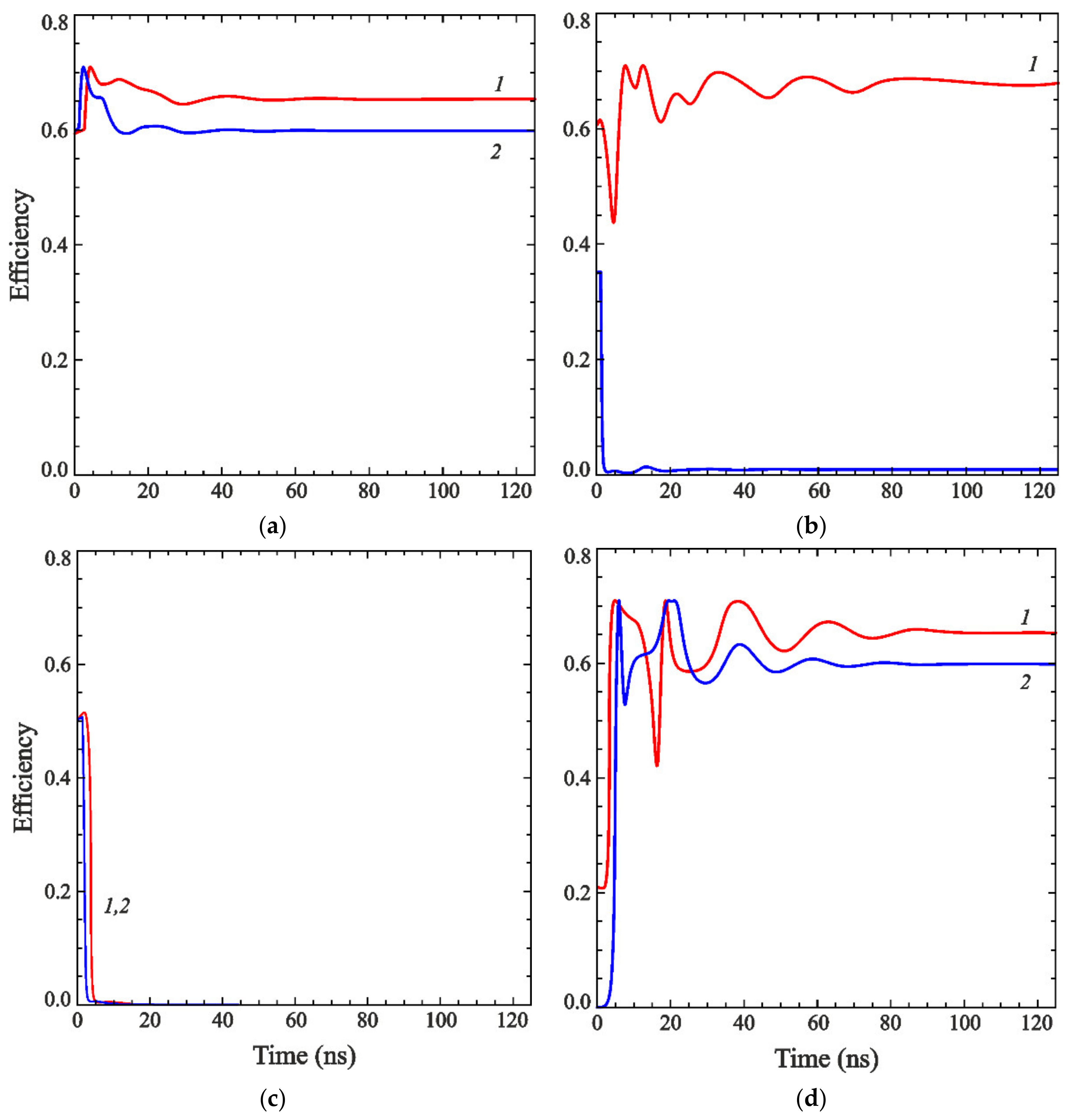
28]. The simulation reveals all of the possible regimes discussed above. In the simulations, we choose large initial values of the amplitudes close to the amplitudes of uncoupled gyrotrons, which was necessary since the gyrotrons operated in the hard-excitation mode. Depending on the phase difference, different regimes are observed.
Figure 6a illustrates the regime of peer-to-peer locking. Under somewhat different initial conditions, the first gyrotron suppresses the oscillation of the second one, as is shown in
Figure 6b. Moreover, the complete mutual suppression of both gyrotrons (oscillation death) may take place (
Figure 6c).
On the contrary, the coupling of the gyrotrons may also lead to the excitation of one gyrotron by another.
Figure 6d illustrates the case when the initial amplitude of the second gyrotron is zero. If the gyrotrons are uncoupled, this state would be stable because the gyrotron operates in the hard-excitation mode. However, the first gyrotron drives the second gyrotron. Its oscillation starts to grow, and finally, the locking mode is established.
The results obtained by the simulation of the DDE model (10) are in a rather good agreement with the results obtained in the small-delay approximation, as shown in
Figure 4b. However, in the case of finite delay, there appears an additional phase shift
, where
is the oscillation frequency [
25,
26]. Thus, the phase advance
should be adjusted to obtain a good agreement. When
is set to
, a very good agreement is observed.
5. Discussion and Conclusions
In this article, we present the model of the peer-to-peer locking of two coupled gyrotrons. The gyrotrons are assumed to operate in the hard-excitation mode, which is necessary to obtain high values of the electron orbital efficiency. The system demonstrates a behavior similar to that reported in our previous work [
25,
26], where delay-coupled oscillators with weak cubic nonlinearity were studied. In particular, depending on the phase of the coupling signal, either dissipative or conservative coupling may dominate. The dissipative coupling is more favorable for peer-to-peer locking because of the much wider locking bandwidth.
An approximate theory of phase locking is developed based on the generalized Adler’s equation. However, this approximation is valid only for small frequency detuning and weak coupling.
A more rigorous analysis in the case of small delay is presented. This approximation allows for a detailed bifurcation analysis by using XPPAUT software. Such analysis is very useful because the domains of phase locking may have a very complicated structure. For the typical parameters of high-power fusion gyrotrons, the locking bandwidth is on the order of 100 MHz.
To verify the results, we performed a numerical integration of the DDE model in the case of finite delay time. A good agreement between the two approaches is observed if the phase advance is properly adjusted. The simulations reveal various regimes of interaction of the gyrotrons. In addition to the modes of phase locking, which may be in-phase as well as anti-phase, there exist the regimes of suppression of one gyrotron by another and the mutual suppression of both gyrotrons, i.e., the oscillation death. On the contrary, the excitation of one gyrotron by another is observed.


