Article

Ultrawideband Cross-Polarization Converter Using Anisotropic Reflective Metasurface

by
Tauqir Ahmad
1,
Arbab Abdur Rahim
1,*,
Rana Muhammad Hasan Bilal
1,2,
Adnan Noor
1,
Husnul Maab
1,
Muhammad Ashar Naveed
3,
Abdullah Madni
2,
Muhammad Mahmood Ali
4,5 and
Muhammad Ahsan Saeed
6,*
1
Faculty of Electrical Engineering, Ghulam Ishaq Khan Institute of Engineering Sciences and Technology, Topi 23640, Pakistan
2
Department of Electrical Engineering, Lahore University of Management Sciences (LUMS), Lahore 54792, Pakistan
3
Department of Electronic Engineering, The Islamia University of Bahawalpur, Bahawalpur 63100, Pakistan
4
Centre for Mathematical Modelling and Intelligent Systems for Health and Environment (MISHE), F91 YW50 Sligo, Ireland
5
Department of Computing & Electronic Engineering, Institute of Technology Sligo, Ash Lane, F91 YW50 Sligo, Ireland
6
Division of Electronics and Electrical Engineering, Dongguk University, Seoul 04620, Korea
*
Authors to whom correspondence should be addressed.
Electronics 2022, 11(3), 487; https://doi.org/10.3390/electronics11030487
Submission received: 22 December 2021 / Revised: 28 January 2022 / Accepted: 2 February 2022 / Published: 8 February 2022

Abstract

:
Broadband metasurface-based devices are essential and indispensable in modern wireless communication systems. This paper presents an ultra−wideband and wide incident angle reflective cross−polarization converter metasurface. The unit cell of the proposed structure is a 45° rotated anisotropic meta−sheet developed by cutting the rhombus−shaped patch from the central part of the square patch. The unit cell’s top structure and ground blocking sheet are made of copper, whereas a dielectric substrate (FR−4) is used as an intermediate spacer between them. The unit cell thickness is minimal compared to the operating wavelength ( 1 / 14 λ , where λ is the wavelength of the starting frequency of 13 GHz of the operating band). The proposed structure efficiently converts linearly polarized waves into their orthogonal component, with a polarization conversion ratio of (PCR > 90%) over a broad frequency spectrum of 13 GHz to 26 GHz. The physical origin of polarization conversion is also depicted using surface current distribution plots. An ultra−wideband and highly efficient polarization conversion (above 90%) is achieved with the help of strong electromagnetic resonance coupling between the upper and lower layer of the metasurface. This kind of ultra−wideband polarization conversion metasurface can be employed in satellite communication, radar cross−section reduction, and navigation systems.

1. Introduction

Metamaterials have gained much interest in the optics research community over the last couple of years because of their unusual electromagnetic (EM) wave manipulation properties, leading to new applications [1,2,3,4,5,6,7]. Metasurfaces, the 2D counterpart of metamaterials [8,9,10,11], can control EM waves in a low−profile manner by specially designed sub−wavelength meta−structures with proper optimization. They are widely used in constructing various meta−devices, including absorbers, holograms, lenses, and sensors [12,13,14,15,16,17]. They can alter the amplitude, phase, and polarization of EM waves due to controlling the geometric parameters of the underlying unit cell, and have found potential applications in various fields, including antenna gain enhancement [18,19], radar cross−area reduction [20], and MIMO antenna isolation [21]. Polarization converters have been actively used in the microwave, terahertz, and even optical frequencies due to their unique properties in polarization manipulation and their potential for rotating EM waves. Using a metasurface to modify the polarization state of EM waves has been demonstrated to be a successful strategy in various investigations. However, realizing a large bandwidth metasurface is challenging and an area of interest for researchers. Resultantly, the most commonly used research strategies to implement the polarization conversion metasurface are transmission mode and reflection mode metasurfaces [22,23,24].
Polarization is one of the essential features of EM waves and can be classified into three major types: linear, circular, and elliptical. As a result of the advantages of circular polarization, the circularly polarized (CP) antenna plays a significant role in communication systems, such as satellites and rockets [25]. Conventionally, birefringent crystals are used for polarization controllers [26]. The simplest type of birefringence is uniaxial, which means that anisotropy is governed in a single direction, whereas the perpendicular directions are optically equivalent. Thus, rotating the material along the optical axis will not change the optical behavior of the material. The wave having polarization perpendicular to the optic axis is governed by a refractive index called the ordinary refractive index (no), whereas when the polarization of the EM wave is along the direction of the optical axis, it is called the extraordinary refractive index (ne), and their difference is birefringence: ∆n = no − ne.
Due to the difference in refractive indexes, the orthogonal components of EM waves travel with different speeds, which causes phase difference and results in polarization conversion. The polarization conversion of EM waves can be converted through a half−wave plate and quarter−wave plate. Using Faraday’s effects, polarization can also be achieved; however, such devices often have large volumes and a narrow bandwidth, and these attributes severely limit their application. As a result, researchers have been striving to develop polarization converters that are more efficient, compact, have a large bandwidth, and are easily fabricable [27]. Even though various polarization converters have been documented, they all have substantial disadvantages, such as a limited bandwidth and larger unit cell thickness than the operating wavelength. To overcome these flaws, a variety of strategies have been employed. Recently, multilayer and multiple resonators have been used to achieve a wide bandwidth in polarization conversion metasurfaces [28,29,30]. However, these techniques limit their implementation in practical applications due to a large thickness and costly fabrication. In our proposed metasurface, we address these issues by designing an ultrathin, simple, and single−layer meta−structure. Recently, various operating frequency spectrums have reported reflective metasurface−based polarization converters. For a perfect polarization converter, a high anisotropic or multiple plasmon resonance−based metasurfaces were exploited to attain wideband features. Resultantly, there are different types of metasurface−based polarization converters, such as double arrowhead [31], V−shaped [32], U−shaped [33], and L-shaped [34].
This paper suggests an ultra-broadband and wide incident angle polarization converter reflective metasurface with simple, highly efficient anisotropic unit cell geometry. The proposed structure is single layer and easy to fabricate compared to multilayer structures because broadband multilayer structures need special and complicated techniques for fabrication. We utilized a FR−4 dielectric substrate, which is more readily accessible than F4B−2 and has a thinner thickness of 1.6 mm compared to 3 mm for F4B−2. The operating frequency range is considered from 11 to 27 GHz to examine its reflection characteristics. The polarization conversion ratio (PCR) is above 90% in the 13 to 26 GHz frequency band. The proposed broadband and highly efficient metasurface could be very effective for the applications of radar cross−section reduction and MIMO antennas, etc.

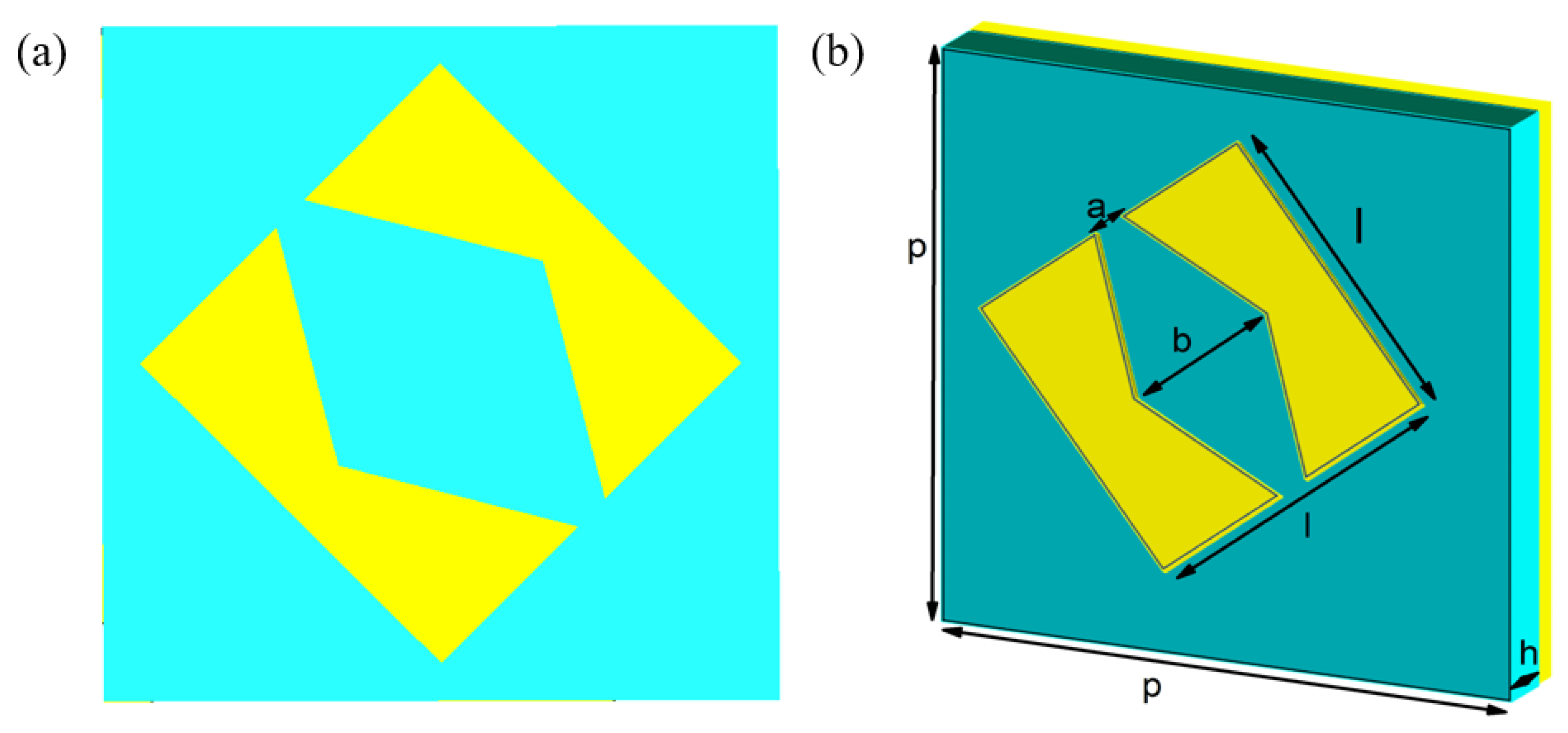
2. Design of a Unit Cell
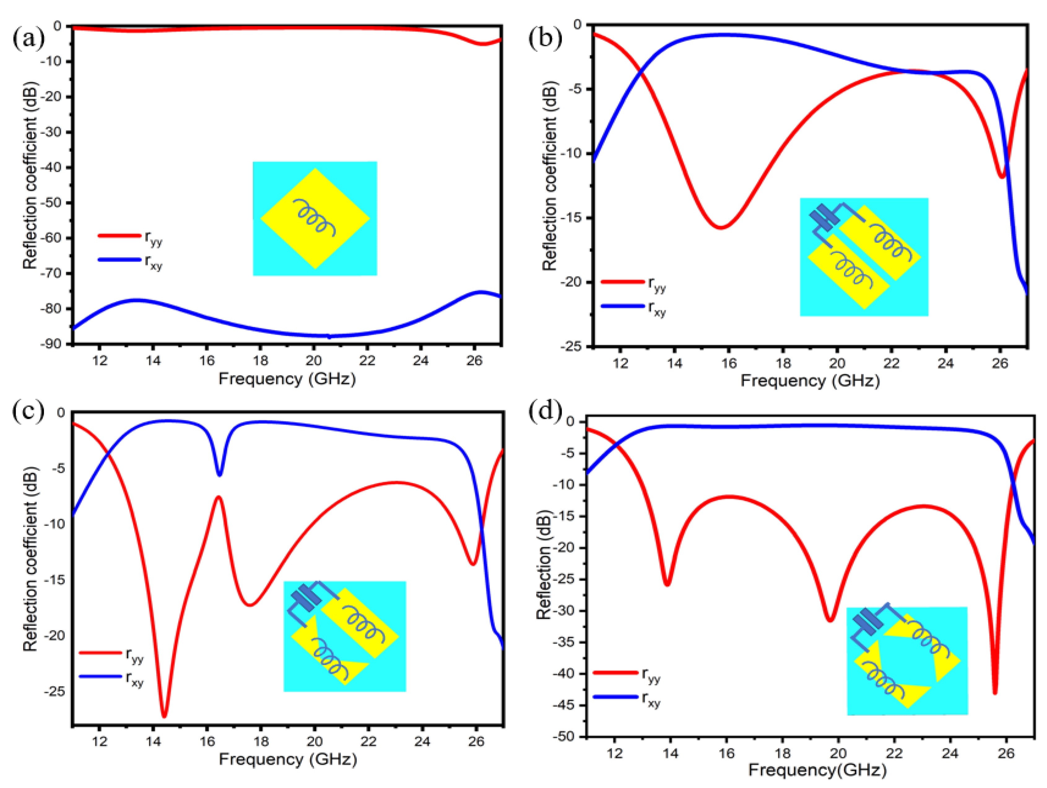
For EM waves absorption, isotropic reflective metasurfaces are typically used with low co− and cross−polarized reflection components. If we break the symmetry of the isotropic unit cell, its cross−polarized coefficient increases due to the anisotropic effect faced by the geometry [35]. It signifies that EM waves convert from x−polarized to y−polarized or (y−polarized to x−polarized).
Following a similar idea, we proposed an ultra−broadband and highly efficient reflective metasurface based on a hollow rhombus−type−shaped unit cell, as depicted in Figure 1, with the physical dimensions of a unit cell as P = 7 mm, l = 4 mm, h = 1.6 mm, a = 0.4 mm, and b = 2.8 mm. The postulated unit cell is made up of three layers: the top and bottom layers are composed of copper, each with a thickness of 0.035 mm and electrical conductivity of σ = 5.80 × 10^7 S/m. The central layer consists of FR−4 with a thickness of h = 1.6 mm and dielectric constant and loss tangent of ϵr = 4.3, tanδ = 0.025, respectively. We follow four steps to convert this isotropic shape into anisotropic to achieve an efficient polarization conversion.
  • First, a 4 × 4 mm copper patch is rotated at 45 w.r.t. x−axis and simulated. Co−polarized ( r y y ) and cross−polarized ( r x y ) coefficients are depicted in Figure 2a. It can be observed that r y y approaches 0 dB, whereas r x y is below −75 dB. It is evident that there is no polarization conversion;
  • A cut with a width of 0.4 mm is applied at 45 to the x− and y−axes. Figure 2b illustrates simulated results. In the frequency ranges of 14.2 GHz to 18 GHz, r y y is less than −10 dB, whereas r x y is more significant than −1 dB. It is evident that there is polarization conversion, but the operating bandwidth is narrow, so we move forward for further modifications;
  • Figure 2c shows simulated results after eliminating a triangular patch from the inner side of one slice. This provides a broadband polarization conversion over the frequency range of 12 GHz to 26 GHz. However, the efficiency does not improve across all frequency ranges. To improve the efficiency of polarization conversion, we further modify the structure;
  • A triangular shape of the same size is removed from the second slice; the structure adopts a shape similar to a hollow rhombus. It is noteworthy that r y y is below −10 dB, and r x y is approaching 0 dB over the frequency bands of 13 GHz to 26.2 GHz. The polarization conversion results are relatively efficient, up to 90%, and the operating bandwidth is also high (Figure 2d).
Mathematically, the relation between effective electric and magnetic dipole moments i.e., p and m respectively, and the incident fields (E and H) can be described through the following equations [35]:
[ p m ] = [ p x p y m x m y ] = [ P e e x x P e e x y P e m x x P e m x y P e e y x P e e y y P e m y x P e m y y P m e x x P m e x y P m m x x P m m x y P m e y x P m e y y P m m y x P m m y y ] [ E x E y H x H y ]  
where P e m represent for electric–magnetic polarizability and P e e x x can be defined as P e e x x = p x E x | E y , H x , H y = 0 . Moreover, the relation between effective surface electric current and magnetic current densities i.e., J s and M s respectively, and the incident fields can also be written as [35]:
[ J s M s ] = [ J x J y M x M y ] = [ P e e x x P e e x y P e m x x P e m x y P e e y x P e e y y P e m y x P e m y y P m e x x P m e x y P m m x x P m m x y P m e y x P m e y y P m m y x P m m y y ] [ E x E y H x H y ]
Considering the Ey polarized incidence wave i.e.,
[ E H ] = [ 0 E y H x 0 ]    
then, J x and M y will radiate the Ex polarized wave because
J x = i ω ( P e e x y E y + P e m x x H x ) 0
M y = i ω   ( P m e y y E y + P m m y x H x ) 0
As we have a nonzero cross−polarized field, and orthogonal polarization is also nonzero, as represented by the following equations,
p x = P e e x y E y + P e m x x H x 0
m y = P m e y y E y + P m m y x H x 0
Furthermore, the effective impedance, permittivity, and permeability are related to the reflection and transmission coefficients. The below equations describe the relationship [17].
Z = ± ( 1 + S 11 ) 2 S 21 2 ( 1 S 11 ) 2 S 21 2
ε e f f e c t i v e = n Z
µ e f f e c t i v e = n × Z
Following the steps represented by simulation results, we can control the reflection and transmission coefficients and can meet impedance−matching conditions. As a result, there will be minimum co polarization reflection and maximum polarization conversion.
Z represents impedance, and n, k, and h represent the unit cell’s refractive index, wave number, and thickness, respectively.
Secondly, the resonance frequency f 1 L C is inversely proportional to inductance and capacitance effects. As depicted by the above four steps, the inductive and capacitive effect varies when we break the unit cell symmetry, which can be analyzed from the simulated results of the co−polarized and cross−polarized coefficients of the reflected wave. When increasing or decreasing the gap between the metallic patches, the capacitance will decrease and increase. We can achieve a strong electric/magnetic resonance by adequately adjusting the L and C through variations of top metallic patches, as shown in Figure 2d.

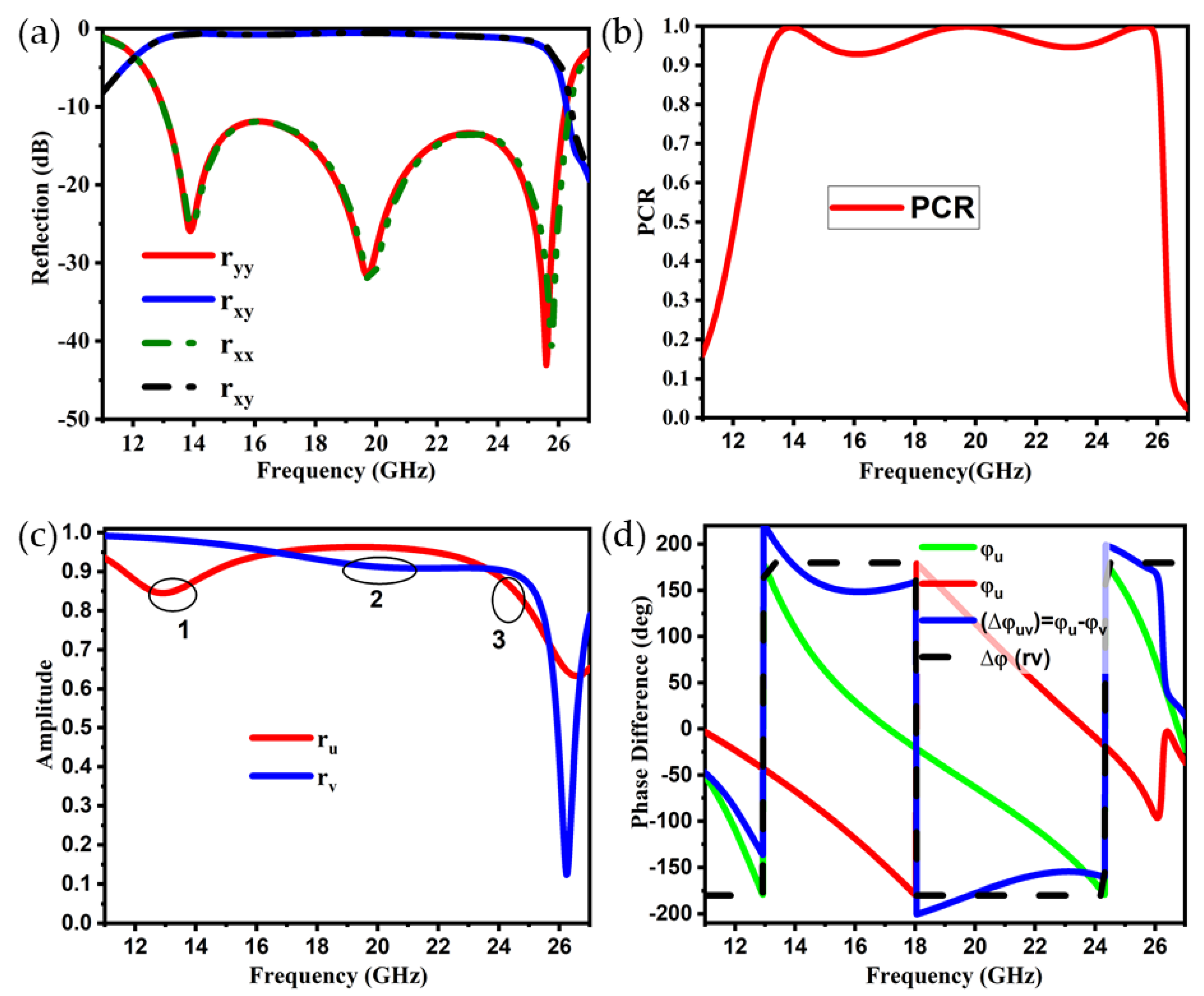
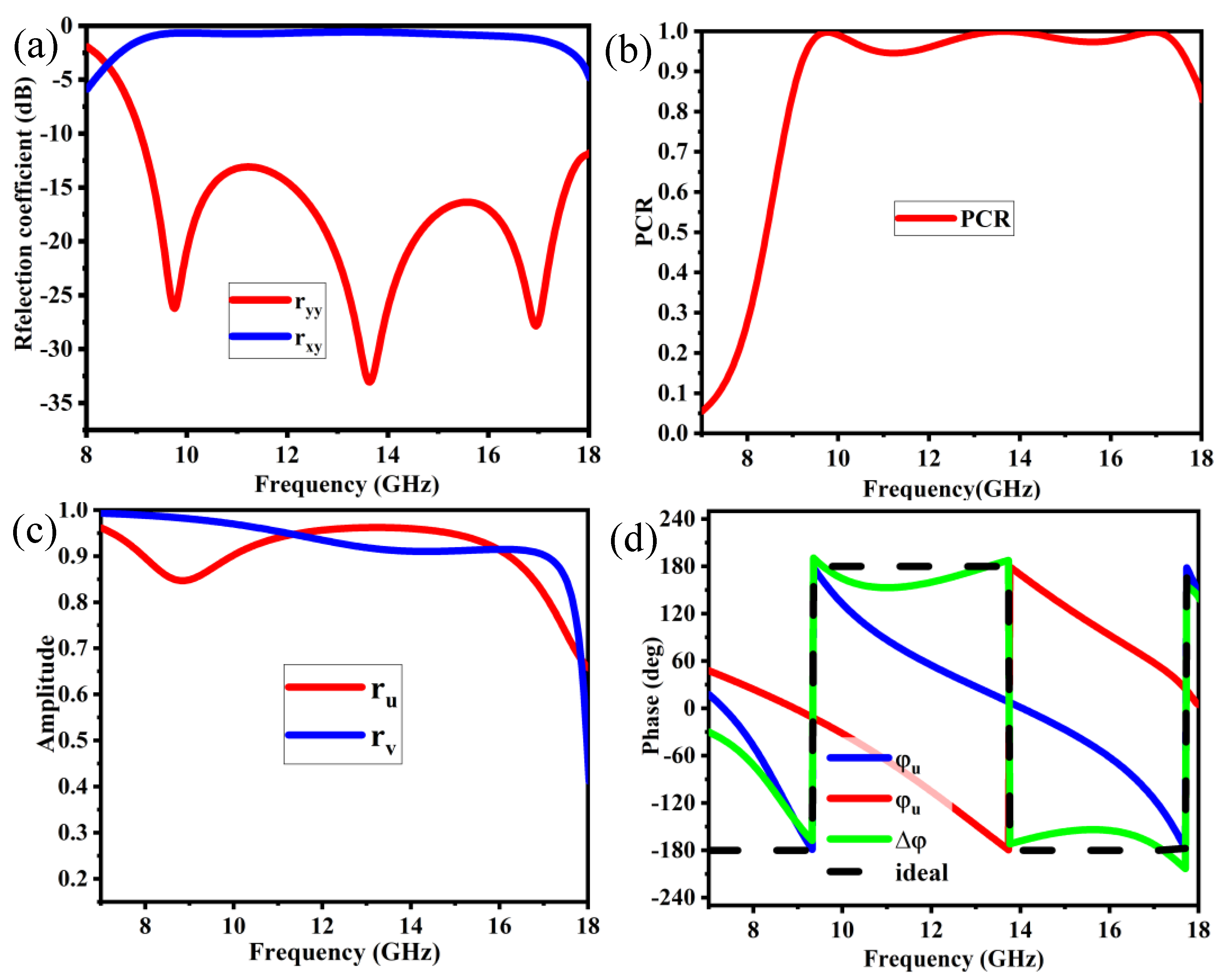
3. Performance Analysis and Simulation Results

The commercially available CST Microwave Studio was used to analyze and optimize the proposed metasurface unit cell design. To perform the simulation analysis, the “unit cell” boundary conditions option is specified for x m i n , x m a x , y m i n , and y m a x , and the open add space option is employed for z m i n and z m a x . Finally, a frequency−domain solver is used for simulation. When electromagnetic waves strike the metasurface, the reflected waves have two components: a co−polarized field, represented by r y y and r x x , which have the same polarization to the incident field, and a cross−polarized field coefficient, represented as r x y and r y x , which are orthogonal to the incident field. The co− and cross−polarized coefficients can be defined as | r y y | = E y r / E y i and | r x y | = E x r / E y i , respectively, whereas the analogous coefficients for an x−polarized wave are | r x x | = E x r / E x i and | r y x | = E y r / E x i . The co−polarization and cross−polarization reflection coefficients of the TE or TM polarized incident wave are r y y and r x y or ( r x x and r y x ).
For this analysis, we solely evaluated the TE mode. Due to diagonal symmetry in the geometry, the designed meta−unit cell is equally effective for the TM mode. When the co−polarized coefficient decreases and the cross−polarized coefficient raises, cross−polarization conversion occurs. The results are identical for the x−polarized incidence wave or y−polarized incidence wave due to the unit cell’s diagonal symmetry. The main criterion for an above 90% cross−polarization conversion is that the co−polarized coefficients should be less than −10 dB and the cross−polarization coefficient value should be greater than −1 dB, respectively, ( r x x < −10 dB and r y y < −10 dB) and ( r x y > −1 dB and r y x > −1 dB). The co−polarized and cross−polarized coefficients in the operative frequency range of 13 GHz to 26.2 GHz are ( r y y < −10 dB) and ( r x y > −1 dB), respectively, according to these conditions, as shown in Figure 3a. The polarization conversion efficiency is anticipated to be better than 90% for the assessment frequency range.
To further understand the performance of the proposed metasurface, we scrutinize the PCR in the operating frequency band. To calculate the PCR, divide the square of the cross−polarized reflection coefficient | r x y | 2 by the sum of the squares of the co−polarized coefficient | r y y | 2 and cross−polarized reflection coefficient | r x y | 2 [29]. Equation (11) shows the PCR for the case of linearly y−polarized waves.
P C R = | r x y | 2 | r y y | 2 + | r x y | 2
For the specified frequency range of 13 GHz to 26.2 GHz, the PCR > 0.9, as shown in Figure 3b. Hence, the polarization conversion efficiency is greater than 90%.

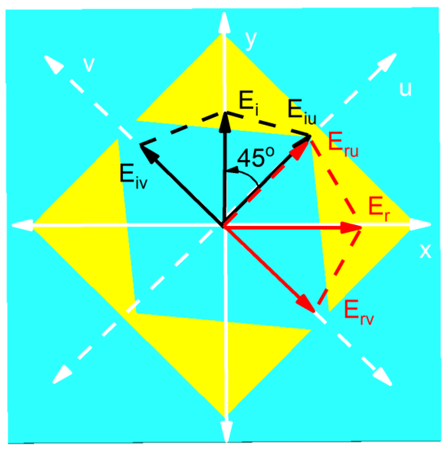
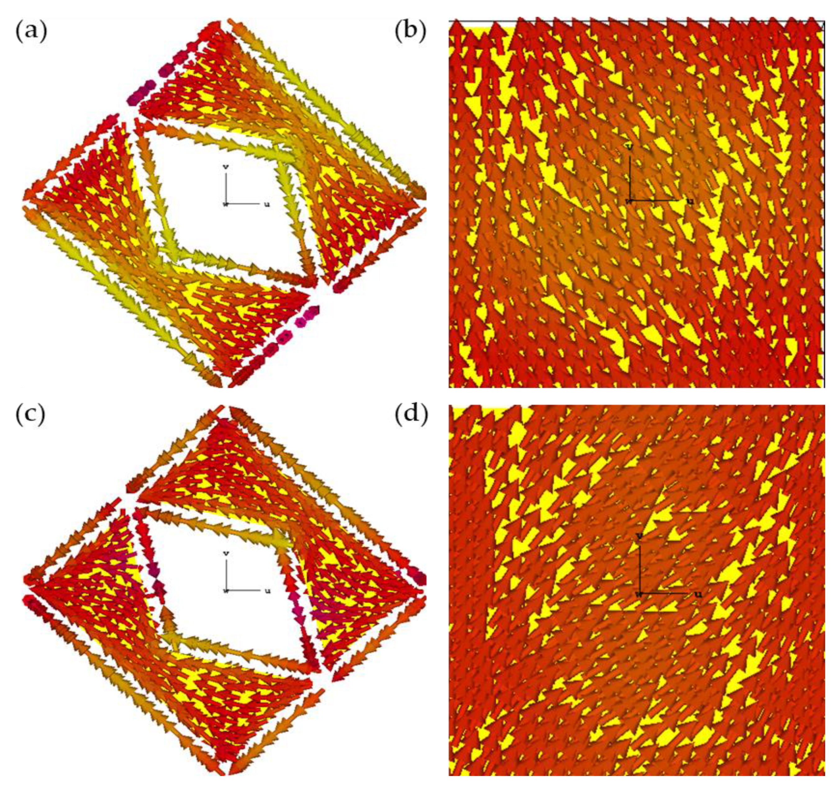
4. Decomposed U−V Incident Analysis

Some mathematical formulations are presented here to better understand the polarization conversion mechanism. Generally, x− and y−polarized incident waves are mathematically represented as E x i = E x i e x and E y i = E y i e y , where ( e x , e y ) are unit vectors along the x− and y−axes. Furthermore, as we discussed earlier, the co− and cross−polarized coefficients can be defined as | r y y | = E y r / E y i and | r x y | = E x r / E y i , respectively, whereas the analogous coefficients for an x−polarized wave are | r x x | = E x r / E x i and | r y x | = E y r / E x i . To analyze the anisotropy of the structure, a new coordinate system of u− and v−axes are defined, and, for that, the axes are rotated at 45° with respect to the x− and y−axes.
We only consider the y−polarized incidence EM wave for analysis in order to keep it simple. Figure 4 depicts the polarization converter anisotropic geometry, including mutually perpendicular symmetric u− and v−axes. When the y−polarized wave illuminates the metasurface, it gets decomposed into two components along the u− and v−axes: E y i = u ^ E u i e j φ + v ^ E v i e j φ . When the reflected components of the impinging waves are composed together, it leads to an x−polarized wave: E x r = u ^ E r u e j φ u + v ^ E r v e j φ v , where φ u and φ v are the phases of r u and r v , respectively. E y i and E x r can also be written as Equations (12) and (13).
E y i = E u i exp ( j k z ) e u + E v i exp ( j k z ) e v = E y i c o s ( 45 ° ) exp ( j k z ) ( e u + e v ) .
E x r = E u r e u + E v r e v = r u E u i e u + r v E v i e v = | E y i | ( r u c o s ( 45 ° ) exp ( jkz + φ u ) e u + r v c o s ( 45 ° ) exp ( jkz + φ v ) e v ) .
We considered minimum dielectric losses for the structure because it is backed with copper, and most of the energy is considered as reflected, so the amplitudes of r u and r v are approximately equal— r u = r v = 1 —as shown in Figure 3c. The same method can be applied for the x−polarized incident wave, and the relation can also be considered for co−polarized coefficients along the u− and v−axes:   | r u | = E r u / E i u and | r v | = E r u / E i v . The u− and v−polarized coefficients ( r u and r v ) are independent because of the anisotropic nature of the unit cell. If we consider the ideal scenario and neglect the loss tangent of copper, the magnitude of r u and r v is unity ( r u = r v = 1 ), and phase difference Δ φ u v = φ u φ v = 180°, then the reflected field E r will be oriented along the x−axis, validating the cross−polarization conversion.
To verify the amplitude and phase conditions of r u and   r v , simulation results are plotted in Figure 3c. It can be observed that the amplitudes of these components are approximately equal to unity, and that there is a 180° phase difference between them for a wide frequency band ranging from 13 GHz to 26 GHz, conforming to the broadband polarization conversion.

5. Working Mechanism

When the EM wave interacts with the meta−atom, it produces electric and magnetic dipole moments. Due to the resonator’s bi−anisotropy, electric and magnetic fields can be coupled to these dipole moments. Equation (17) depicts the link between incident fields and effective dipole moments:
[ p m ] = [ p e e p e m p m e p m m ] [ E H ] ,
where p = [ p x p y ] represents electric dipole moments and m = [ m x m y ] magnetic dipole moments, respectively, and the electric and magnetic fields are E, H. p m e represents magneto−electric polarizability. The effective impedance of the metasurface is given by Equation (15).
Z ( ω ) = μ ( ω ) / ϵ ( ω ) ,
where μ ( ω ) and ϵ ( ω ) are the magnetic permeability and electric permittivity, Z ( ω ) is the surface impedance of the metasurface, and all are frequency dependent. At the normal incidence, the reflection coefficient is given as:
R ( ω ) = ( Z ( ω ) Z ) / ( Z ( ω ) + Z )
where Z = 377   Ω denotes the free space impedance and ω r represents the resonance frequency. When the impedance of the metasurface is greater than the impedance of free space, Z ( ω r ) > Z 0 , the reflection coefficient approaches unity, and the surface behaves like a high impedance surface (HIS). An incident EM waves on such a surface will be reflected with an in−phase and unity magnitude, unlike a normal reflective surface, which reflects waves out of phase. As discussed earlier, when orthogonal components reflect 180° or 0°, the polarization of the incident wave will be rotated by 90°, leading to cross−polarization conversion. It can be concluded that the structure behaves as a HIS for one component and a common reflector for another component.
To justify the above discussion and ultra−wideband polarization conversion, the surface current distributions are studied and induced by the time−varying dipole moment induced by time−harmonic electric and magnetic fields. Equation (17) explains the following relationship:
[ J M ] = ι ω [ α e e α e m α m e α m m ] [ E H ] ,
where J = [ J x J y ] T is the electric surface current density, M = [ M x M y ] T is a magnetic surface current density, ( ω ) is the angular frequency, and α m e is the magnetic and electric polarizability. According to Faraday’s law, the time−varying magnetic field B sandwiched between the top metallic structure and the metallic groundsheet produces an opposite−direction surface current. As a result, the resonances of the entire system operate as magnetic responses. At the resonance frequency, μ is divergent, resulting in a relatively large surface impedance z = μ / ϵ and in−phase reflection.
According to the previous discussion, when the current direction on the top and bottom metallic layer is antiparallel, the resonance will be magnetic; otherwise, there will be electric resonance. These resonances are also known as plasmonic resonances. The unit cell’s Plasmon resonance is illustrated in Figure 3c. The exciting unit cell has three plasmon resonances, where 1 and 3 are u−polarized excited states, whereas 2 is v−polarized excited state plasmon resonance. As a result of the multiple resonances, ultra−wideband polarization conversion is achieved. Figure 5 shows the simulation of surface current distribution on the unit cell’s top and bottom metallic layers for two distinct resonance frequencies. At 13.8 GHz, the resonance frequency current flows on the top surface toward the corner aligned with the positive u−axis, and the bottom layer current flows toward the upper right corner, which is antiparallel to the top surface current. This reveals that the resonance at 13.8 GHz is magnetic in nature. The top and bottom currents intensify the magnetic field in the substrate of the metasurface. This leads to an increase in the surface impedance, and the HIS condition is satisfied. The current impedance imbalance in the y−direction causes phase reflection and changes the current flow in the x−direction. Finally, the cross−polarization phenomenon occurs, allowing for the conversion of a y−polarized wave to an x−polarized wave and vice versa.

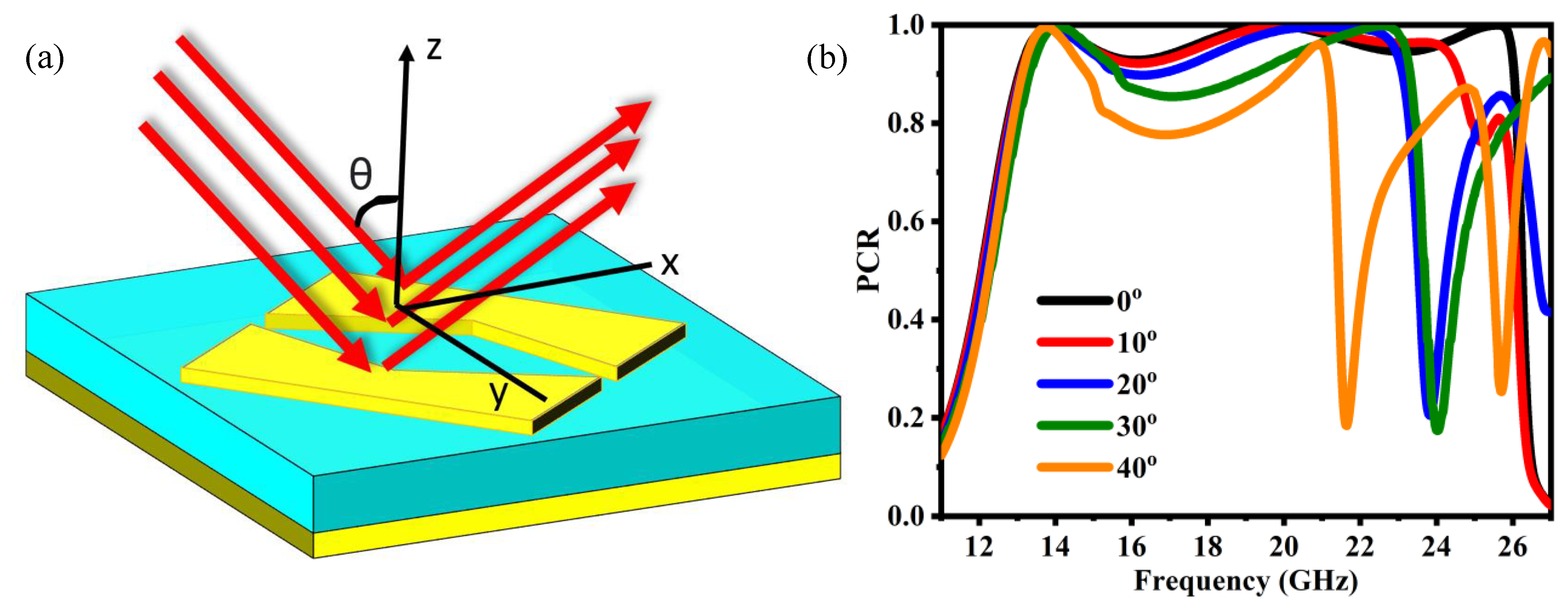
6. Oblique Incidence Waves Performance Analysis

Polarization conversion can be easily achieved through anisotropic structures in reflection mode, but these structures are susceptible to oblique incidence angles. The efficiency of a polarization conversion metasurface can be studied with a wide range of incident angles to forecast its stability and performance. The suggested metasurface polarization conversion performance for oblique incidence must be investigated, as shown in Figure 6. At normal incident waves, the operating bandwidth of the proposed structure is 13 GHz (13 GHz to 26 GHz); as we increase the incident angle, it slightly affects the bandwidth. Considering θ = 10°, the structure is relatively stable for the operating bandwidth. At θ = 20° and 30°, the higher frequency band slightly decreases to 23 GHz and 22.5 GHz, respectively (Figure 6b). For the remaining operational frequencies, the performance is relatively stable. It is ensured that the specified metasurface operates effectively in a large operating band throughout a wide range of incidence angles. Even when the incidence angle reaches 30°, it can operate over the frequency range of 13–22.5 GHz, with a PCR of more than 80%. As a result, the proposed metasurface is effective across a broad range of incidence angles.

7. Parametric Variation

The operational frequency band of the unit cell can be switched to any desired frequency range just by altering its physical dimensions, and, for that, the parameters are readjusted in the CST studio as p = 10 mm, l = 5.2 mm, a = 0.6 mm, b = 4.4 mm, and h = 2.4 mm. The boundary conditions are the same in both cases. As discussed in Section 3, the main criterion for an above 90% cross−polarization conversion is that the co−polarized coefficients should be less than −10 dB and the cross−polarization coefficient value should be greater than −1 dB, respectively: ( r x x < −10 dB and r y y < −10 dB) and ( r x y > −1 dB and r y x > −1 dB). It can be depicted from Figure 7a that the co−polarized coefficient ryy is below −10 dB for the wide frequency band of (9–18 GHz), and the cross−polarized coefficient rxy is above −1 dB. This means that there is a strong polarization conversion. After the simulation, it is evident from Figure 3a and Figure 7a that the operating frequency band of the proposed polarization converter is shifted from (13–26.2 GHz) to (9–18 GHz). It can also be tuned to higher frequencies by lowering the size of the participating unit cell. From Equation (5), the PCR can be demonstrated, and the efficiency at the frequency range of (9–18 GHz) can be predicted. As discussed above, if the PCR approaches unity, the metasurface is 100% efficient. Figure 7b shows the results of Equation (11) for the frequency range of (9–18 GHz). The proposed structure is also efficient at low frequencies. It can be analyzed from the polarization conversion ratio shown in Figure 7b that the P C R > 0.95 for the frequency range (9–18 GHz), which means that the efficiency is greater than 95% and, for some frequencies, approaches near 100%. We used the criteria mentioned above in the Section 4 “decomposed u−v incident analysis.” For polarization conversion, considering the linear−to−cross−polarization case, the magnitude of r u and r v is approximately r u r v 1 , where the slight variation is due to metallic and dielectric losses caused by metal and the FR−4 substrate. Figure 7d shows the phases of r u and r v , which are represented by φ u and Δ φ v , and Δ φ u v represents the phases difference between r u and r v . Through the analysis of Figure 7d, we can conclude that the phase difference in Δ φ u and Δ φ v is approaching Δ φ u v 180 ° . As a result, the suggested structure can effectively transform a y−polarized wave to an x−polarized wave at low frequencies and vice versa.

8. Conclusions

In summary, this paper proposed an ultra−wideband, highly efficient, wide−angle cross−polarization converter reflective metasurface. A broadband cross−polarization conversion was achieved for a wide frequency range of 13–26 GHz. Numerical simulations were performed to validate the performance and justify the claim of a large operational bandwidth. To demonstrate the physical mechanism behind the polarization conversion, the reflected amplitude and phase difference between the u− and v−axes and surface current distribution plots were presented for different resonance frequencies at the top and bottom metallic layers. In addition, the polarization converter showed a stable performance over a wide range of oblique incidence angles. Resultantly, the proposed metasurface behaved like a high impedance surface and reflected the incidence wave in its orthogonal counterpart. Furthermore, by tuning the geometric parameters of the unit cell, the operating spectrum of the suggested metasurface was also shifted to lower frequencies, i.e., 9–18 GHz. In the low−frequency spectrum, the conversion efficiency was also above 90%. The proposed converter has many potential applications, including satellite communication, radar cross−section reduction, and navigation systems.

Author Contributions

Conceptualization, T.A. and R.M.H.B.; methodology, T.A.; software, T.A.; validation, R.M.H.B., A.A.R. and M.A.N.; formal analysis, A.N. and H.M.; investigation, T.A., A.M. and M.A.S.; resources, A.A.R. and H.M.; data curation, T.A.; writing—original draft preparation, T.A.; writing—review and editing, M.A.N.; R.M.H.B. and A.M.; visualization, M.M.A. and A.A.R.; supervision, A.A.R., R.M.H.B. and A.N.; project administration, M.A.S. and M.M.A.; All authors have read and agreed to the published version of the manuscript.

Funding

This research received no external funding.

Conflicts of Interest

The authors declare no conflict of interest.

References

  1. Pfeiffer, C.; Grbic, A. A printed, broadband Luneburg lens antenna. IEEE Trans. Antennas Propag. 2010, 58, 3055–3059. [Google Scholar] [CrossRef]
  2. Bilal, R.; Baqir, M.; Iftikhar, A.; Ali, M.; Rahim, A.; Akhtar, M.N.; Mughal, M.; Naqvi, S. A Novel Omega Shaped Microwave Absorber with Wideband Negative Refractive Index for C-Band Applications. Optik 2021, 242, 167278. [Google Scholar] [CrossRef]
  3. Kim, I.; Kim, W.-S.; Kim, K.; Ansari, M.A.; Mehmood, M.Q.; Badloe, T.; Kim, Y.; Gwak, J.; Lee, H.; Kim, Y.-K. Holographic metasurface gas sensors for instantaneous visual alarms. Sci. Adv. 2021, 7, eabe9943. [Google Scholar] [CrossRef]
  4. Mahmood, N.; Kim, I.; Mehmood, M.Q.; Jeong, H.; Akbar, A.; Lee, D.; Saleem, M.; Zubair, M.; Anwar, M.S.; Tahir, F.A. Polarisation insensitive multifunctional metasurfaces based on all-dielectric nanowaveguides. Nanoscale 2018, 10, 18323–18330. [Google Scholar] [CrossRef] [PubMed]
  5. Baqir, M.; Choudhury, P. On the VO2 metasurface-based temperature sensor. JOSA B 2019, 36, F123–F130. [Google Scholar] [CrossRef]
  6. Naveed, M.A.; Ansari, M.A.; Kim, I.; Zubair, M.; Riaz, K.; Tauqeer, T.; Rho, J.; Mehmood, M.Q. A Pragmatic Metasurface with Asymmetric Spin Interactions. In Proceedings of the CLEO, San Jose, CA, USA, 9–14 May 2020; p. FM4B. 5. [Google Scholar]
  7. Bilal, R.; Saeed, M.; Choudhury, P.; Baqir, M.; Kamal, W.; Ali, M.M.; Rahim, A.A. Elliptical metallic rings-shaped fractal metamaterial absorber in the visible regime. Sci. Rep. 2020, 10, 14035. [Google Scholar] [CrossRef]
  8. Xu, P.; Wang, S.-Y.; Geyi, W. A linear polarization converter with near unity efficiency in microwave regime. J. Appl. Phys. 2017, 121, 144502. [Google Scholar] [CrossRef]
  9. Mo, W.; Wei, X.; Wang, K.; Li, Y.; Liu, J. Ultrathin flexible terahertz polarization converter based on metasurfaces. Opt. Express 2016, 24, 13621–13627. [Google Scholar] [CrossRef] [PubMed]
  10. Naveed, M.A.; Ansari, M.A.; Kim, I.; Badloe, T.; Kim, J.; Oh, D.K.; Riaz, K.; Tauqeer, T.; Younis, U.; Saleem, M. Optical spin-symmetry breaking for high-efficiency directional helicity-multiplexed metaholograms. Microsyst. Nanoeng. 2021, 7, 1–9. [Google Scholar] [CrossRef]
  11. Luo, S.; Li, B.; Yu, A.; Gao, J.; Wang, X.; Zuo, D. Broadband tunable terahertz polarization converter based on graphene metamaterial. Opt. Commun. 2018, 413, 184–189. [Google Scholar] [CrossRef]
  12. Bilal, R.; Baqir, M.; Choudhury, P.; Naveed, M.; Ali, M.; Rahim, A. Ultrathin broadband metasurface-based absorber comprised of tungsten nanowires. Results Phys. 2020, 19, 103471. [Google Scholar] [CrossRef]
  13. Naveed, M.A.; Bilal, R.M.H.; Rahim, A.A.; Baqir, M.A.; Ali, M.M. Polarization-insensitive dual-wideband fractal meta-absorber for terahertz applications. Appl. Opt. 2021, 60, 9160–9166. [Google Scholar] [CrossRef] [PubMed]
  14. Ansari, M.A.; Kim, I.; Rukhlenko, I.D.; Zubair, M.; Yerci, S.; Tauqeer, T.; Mehmood, M.Q.; Rho, J. Engineering spin and antiferromagnetic resonances to realize an efficient direction-multiplexed visible meta-hologram. Nanoscale Horiz. 2020, 5, 57–64. [Google Scholar] [CrossRef]
  15. Wang, Y.; Zhao, C.; Wang, J.; Luo, X.; Xie, L.; Zhan, S.; Kim, J.; Wang, X.; Liu, X.; Ying, Y. Wearable plasmonic-metasurface sensor for noninvasive and universal molecular fingerprint detection on biointerfaces. Sci. Adv. 2021, 7, eabe4553. [Google Scholar] [CrossRef] [PubMed]
  16. Bilal, R.; Baqir, M.; Choudhury, P.; Ali, M.M.; Rahim, A.A. On the specially designed fractal metasurface-based dual-polarization converter in the THz regime. Results Phys. 2020, 19, 103358. [Google Scholar] [CrossRef]
  17. Naveed, M.A.; Bilal, R.M.H.; Baqir, M.A.; Bashir, M.M.; Ali, M.M.; Rahim, A.A. Ultrawideband fractal metamaterial absorber made of nickel operating in the UV to IR spectrum. Opt. Express 2021, 29, 42911–42923. [Google Scholar] [CrossRef]
  18. Garcia-Marin, E.; Masa-Campos, J.L.; Sanchez-Olivares, P.; Ruiz-Cruz, J.A. Bow-tie-shaped radiating element for single and dual circular polarization. IEEE Trans. Antennas Propag. 2019, 68, 754–764. [Google Scholar] [CrossRef]
  19. Bilal, R.M.H.; Rahim, A.A.; Maab, H.; Ali, M.M. Modified wang shaped ultra-wideband (UWB) fractal patch antenna for millimetre-wave applications. In Proceedings of the 2018 Progress in Electromagnetics Research Symposium (PIERS-Toyama), Toyama, Japan, 1–4 August 2018; pp. 280–284. [Google Scholar]
  20. Sun, H.; Gu, C.; Chen, X.; Li, Z.; Liu, L.; Xu, B.; Zhou, Z. Broadband and broad-angle polarization-independent metasurface for radar cross section reduction. Sci. Rep. 2017, 7, 1–9. [Google Scholar] [CrossRef] [Green Version]
  21. Bilal, R.; Naveed, M.; Baqir, M.; Ali, M.; Rahim, A. Design of a wideband terahertz metamaterial absorber based on Pythagorean-tree fractal geometry. Opt. Mater. Express 2020, 10, 3007–3020. [Google Scholar] [CrossRef]
  22. Akram, M.R.; Mehmood, M.Q.; Bai, X.; Jin, R.; Premaratne, M.; Zhu, W. High efficiency ultrathin transmissive metasurfaces. Adv. Opt. Mater. 2019, 7, 1801628. [Google Scholar] [CrossRef]
  23. Bilal, R.M.H.; Baqir, M.A.; Choudhury, P.K.; Karaaslan, M.; Ali, M.M.; Altłntas, O.; Rahim, A.A.; Unal, E.; Sabah, C. Wideband microwave absorber comprising metallic split-ring resonators surrounded with E-shaped fractal metamaterial. IEEE Access 2021, 9, 5670–5677. [Google Scholar] [CrossRef]
  24. Baqir, M.; Choudhury, P. On the energy flux through a uniaxial chiral metamaterial made circular waveguide under PMC boundary. J. Electromagn. Waves Appl. 2012, 26, 2165–2175. [Google Scholar] [CrossRef]
  25. Markovich, D.L.; Andryieuski, A.; Zalkovskij, M.; Malureanu, R.; Lavrinenko, A.V. Metamaterial polarization converter analysis: Limits of performance. Appl. Phys. B 2013, 112, 143–152. [Google Scholar] [CrossRef] [Green Version]
  26. Meissner, T.; Wentz, F.J. Polarization rotation and the third Stokes parameter: The effects of spacecraft attitude and Faraday rotation. IEEE Trans. Geosci. Remote Sens. 2006, 44, 506–515. [Google Scholar] [CrossRef]
  27. Chen, C.; Sheng, Y.; Jun, W. Computed a multiple band metamaterial absorber and its application based on the figure of merit value. Opt. Commun. 2018, 406, 145–150. [Google Scholar] [CrossRef]
  28. Feng, M.; Wang, J.; Ma, H.; Mo, W.; Ye, H.; Qu, S. Broadband polarization rotator based on multi-order plasmon resonances and high impedance surfaces. J. Appl. Phys. 2013, 114, 074508. [Google Scholar] [CrossRef] [Green Version]
  29. Deng, G.; Sun, H.; Lv, K.; Yang, J.; Yin, Z.; Chi, B. An efficient wideband cross-polarization converter manufactured by stacking metal/dielectric multilayers via 3D printing. J. Appl. Phys. 2020, 127, 093103. [Google Scholar] [CrossRef]
  30. Li, Y.; Wang, Y.; Cao, Q. A reflective multilayer polarization converter with switchable frequency band. J. Appl. Phys. 2020, 127, 045301. [Google Scholar] [CrossRef]
  31. Lin, B.; Wang, B.; Meng, W.; Da, X.; Li, W.; Fang, Y.; Zhu, Z. Dual-band high-efficiency polarization converter using an anisotropic metasurface. J. Appl. Phys. 2016, 119, 183103. [Google Scholar] [CrossRef]
  32. Xu, J.; Li, R.; Wang, S.; Han, T. Ultra-broadband linear polarization converter based on anisotropic metasurface. Opt. Express 2018, 26, 26235–26241. [Google Scholar] [CrossRef]
  33. Mei, Z.L.; Ma, X.M.; Lu, C.; Zhao, Y.D. High-efficiency and wide-bandwidth linear polarization converter based on double U-shaped metasurface. AIP Adv. 2017, 7, 125323. [Google Scholar] [CrossRef] [Green Version]
  34. Mao, C.; Yang, Y.; He, X.; Zheng, J.; Zhou, C. Broadband reflective multi-polarization converter based on single-layer double-L-shaped metasurface. Appl. Phys. A 2017, 123, 767. [Google Scholar] [CrossRef] [Green Version]
  35. Pouyanfar, N.; Nourinia, J.; Ghobadi, C. Multiband and multifunctional polarization converter using an asymmetric metasurface. Sci. Rep. 2021, 11, 1–15. [Google Scholar] [CrossRef] [PubMed]
Figure 1. Schematic diagram of the proposed meta−unit cell structure: (a) front view, (b) side view.
Electronics 11 00487 g001
Figure 2. Design process along with respective reflection characteristics of the proposed anisotropic reflective metasurface with (a) a 45 rotated square patch, (b) a rectangular split width of 0.4 mm is employed at 45 rotation with respect to xy−axes, (c) a triangular part is cut off from the lower portion, and (d) a rhombus−like shape is removed from 45 rotated square patch.
Electronics 11 00487 g002
Figure 3. Polarization conversion response of proposed metasurface: (a) co− and cross− polarization component r y y and r x y , (b) polarization conversion ratio (PCR), (c) magnitude of orthogonal components r u and r v , and (d) phase difference.
Electronics 11 00487 g003
Figure 4. Illustration of the decomposition of orthogonal components u and v in reflection mode.
Electronics 11 00487 g004
Figure 5. Surface current distribution of the proposed anisotropic reflective metasurface at the top and bottom metallic layers at various resonant frequencies. (a,b) 13.8 GHz, (c,d) 19.7 GHz.
Electronics 11 00487 g005
Figure 6. (a) Schematic representation of the proposed anisotropic reflective metasurface under oblique incident wave; (b) angular dependent PCR of the proposed anisotropic reflective metasurface.
Electronics 11 00487 g006
Figure 7. (a) Co− and cross−polarization component ryy and rxy; (b) Polarization conversion ratio (PCR); (c) Magnitude of orthogonal components ru and rv; (d) Phase difference.
Electronics 11 00487 g007
Publisher’s Note: MDPI stays neutral with regard to jurisdictional claims in published maps and institutional affiliations.

