Article

Proportional Hysteresis Band Control for DC Voltage Stability of Three-Phase Single-Stage PV Systems

by
Hassan Khalkhali
1,
Arman Oshnoei
2 and
Amjad Anvari-Moghaddam
2,*
1
Department of Electrical Engineering, Amirkabir University of Technology, Tehran 159163-4311, Iran
2
Integrated Energy Systems Lab, Department of Energy (AAU Energy), Aalborg University, 9220 Aalborg, Denmark
*
Author to whom correspondence should be addressed.
Electronics 2022, 11(3), 452; https://doi.org/10.3390/electronics11030452
Submission received: 7 January 2022 / Revised: 29 January 2022 / Accepted: 31 January 2022 / Published: 2 February 2022
(This article belongs to the Special Issue Feature Papers in Power Electronics)

Abstract

:
Ensuring the stability of DC-link voltage in grid-connected photovoltaic (PV) systems plays a critical role in their reliable and continuous operation. DC voltage fluctuation and, in the worst case, DC voltage collapse will dramatically hamper real and reactive power delivery to the grid. This is more the case in single-stage inverters with no DC-DC boost stage, and the DC voltage has a varying nature. This paper proposes a new control approach for ensuring DC-link voltage stability in single-stage PV systems. The proposed control strategy is based on an adaptive hysteresis band controller (HBC), supplementing the conventional control blocks. This strategy offers the capability to prevent fast discharge of DC-link capacitor and keeps it within acceptable limits by quickly modifying phase shift applied to inverter PWM through quick calculations. Results show that the approach greatly improves PV system performance, in various operating modes. The proposed control scheme is implemented in the real-time simulator, OPAL-RT, OP5600 to verify its applicability and effectiveness in real time.

1. Introduction

Prospective utilization of photovoltaic (PV) systems is gaining ever-increasing ground both as standalone and grid-connected distributed generation [1]. Customer-level PV systems are becoming more popular in smart cities and developing communities with relatively high resiliency in improving the grid resiliency [2,3]. In this context, significant advances have been gained in the past decade on adoption and managing PV generators and prosumers [4]. Together with demand response (DR) schemes, the incorporation of these renewable energy sources at the consumer’s side promises an even more active interaction between the grid supply and demand entities [5,6].
Generally, PV systems track the maximum power point (MPP) in grid-connected mode to inject the maximum extractable power to the grid network. In recent years, PV systems have also been operated in volt ampere reactive (VAR) mode in addition to injecting active power which could greatly benefit power system stability [7]. Besides active power, significant support to the grid’s reactive power requirements can also be provided through an effective PV voltage-frequency or active-reactive power coordination [8]. Therefore, utilities take increasing interest in obtaining reactive power support from PV systems. Furthermore, the provision of reactive power does not require the availability of solar energy and can be produced at the PV inverter’s full capacity [9]. This is the case when PV arrays are not generating any real power in the early hours at night when the voltage profile may experience some imbalances due to higher consumption compared to late night periods [10]. The reactive power support characteristic makes voltage/var control a more cost-effective service provided by PV systems than from other dynamic reactive power compensators such as using flexible AC transmission system (FACTS) devices.
To utilize PV systems for both active and reactive power generation, considerable attention should be paid to the PV system’s DC-link capacitor as the source of the active power as well as the main element in reactive power support [11]. In fact, DC-link voltage stability is a basic criterion for providing sustained and reliable power delivery into the grid. Operation of PV systems in MPPT is a critical point for DC voltage stability considering the PV’s current-voltage characteristic. In the current source region, a small current increase will probably cause a DC voltage collapse [12]. As a result, the PV system running near the MPP operating point is more sensitive to disturbances. The situation is more severe in the simultaneous MPP tracking (MPPT) and voltage/VAR tracking mode [13].
The control function is even more complicated in single-stage PV systems. Single-stage inverters only consist of an inverter which controls the real and reactive power output as well as generating a grid-compatible voltage [14]. Among power converter topologies, reduced component count converters are popular [15]. Typically, a single-stage inverter has higher power conversion efficiency, lower cost, and higher reliability since the chance of component failure is lower with respect to the two-stage converter [16]. These factors are highly desirable features of renewable energy resources and therefore, the use of single-stage inverters is becoming more common. The control of the whole PV system in this case, however, becomes more complicated [17,18]. To control DC/AC links and reduce power losses of a power converter, modulation and control techniques are proposed in [19,20]. Generally, a grid-connected PV system has two control loops. The inner loop is a pulse width modulation (PWM) loop, realized conventionally through a DC/DC converter, which modulates output currents of the inverter, to meet waveform and phase requirements. The outer loop, realized through a DC/AC inverter, determines the output power of the inverter according to the MPP of PV panels. In single-stage grid-connected PV systems, both loops should be realized simultaneously in one power conversion stage, thus simplifying the system topology at the cost of complicating the control circuit. This topology may make the DC-link voltage more vulnerable to radiation and network disturbances [21].
Few papers have discussed methods to improve DC voltage stability in single-stage PV systems. Libo et al. [22] have used a modified incremental conductance approach to ensure DC-link voltage stability. However, the algorithm may need a fast DSP controller due to cumbersome and complicated calculations. Li et al. [14] introduced a correction in PWM phase shift based on power derivative with respect to PV voltage. As the PV array enters into the current source region, and the value of voltage derivate of PV power exceeds a threshold, a correction term proportional to this derivative is added cumulatively to the phase shift of the inverter PWM in each time step.
However, this method may not be fast enough to compensate DC-link voltage as it accomplishes the correction function in several time steps. Increasing the size of inductance in the LC filter used at the output of the inverter is another way to help maintain a relatively steady DC voltage. However, the reactive power consumption and voltage drop across the inductance will increase remarkably. Moreover, the cost of filter inductance as one of the most expensive elements in grid-connected PV systems will dramatically rise [23,24]. In [25], a power reduction strategy is taken without direct sensing to control and stabilize the DC-link voltage. In a recent work, [26], a P-Q coordination technique based on voltage level control is adopted to improve the voltage stability of a PV system feeding the main grid. Finally, in [27], a tuning method of the conventional PI-based controller is introduced to lower the fluctuations and improve the total harmonic distortion (THD) of the inverter output. However, as mentioned, the fast abrupt changes to the main grid and PV inverter settings may totally undermine the performance of a conventional control mechanism.
In this paper, a new approach is proposed for DC-link voltage stability based on an adaptive proportional HBC principle. The HBC method is a fast and robust control method with simple implementation and a standard digital signal platform. Adaptive HBC has been used widely, mainly to yield active power filtering and drive applications [28,29]. In addition to relieving the high load of calculations in the microcontroller, immediate correction of DC voltage is achieved as it ends up above and below the predetermined upper and lower limits, respectively. The controller acts by adjusting the phase shift applied to the inverter PWM in order to compensate the DC-link voltage drop. The phase shift adjustment occurs in a single step and is proportional to the rate of DC voltage decrease prior to phase shift correction. Therefore, the DC voltage restoration is realized in a fast way, avoiding severe DC-link voltage collapse. The HBC module acts as a supplementary correcting element besides the main MPPT controller to provide a robust voltage characteristic to the grid-connected PV system. As demonstrated, the proposed approach can be reliably implemented in different PV operation modes in combination with the MPP tracking operation.
The rest of this paper has been organized as follows: The proposed grid-connected PV system configuration will be discussed in Section 2. Section 3 will introduce the characteristics of the proposed proportional hysteresis band controller and discuss the operational principle of the modified MPPT method. Simulation results for the proposed approach as well as discussions will be presented to explain the performance of this approach in Section 4. Finally, conclusions will be included in Section 5.

2. Overall System Configuration

The proposed single-stage grid-connected PV system, consisting of PV panels, an inverter, a controller, and filters, is shown in Figure 1.
Sun radiation is the most influential environmental parameter affecting the output of PV systems. The other main parameter is the temperature which is assumed to be constant in this study only for simplicity. 
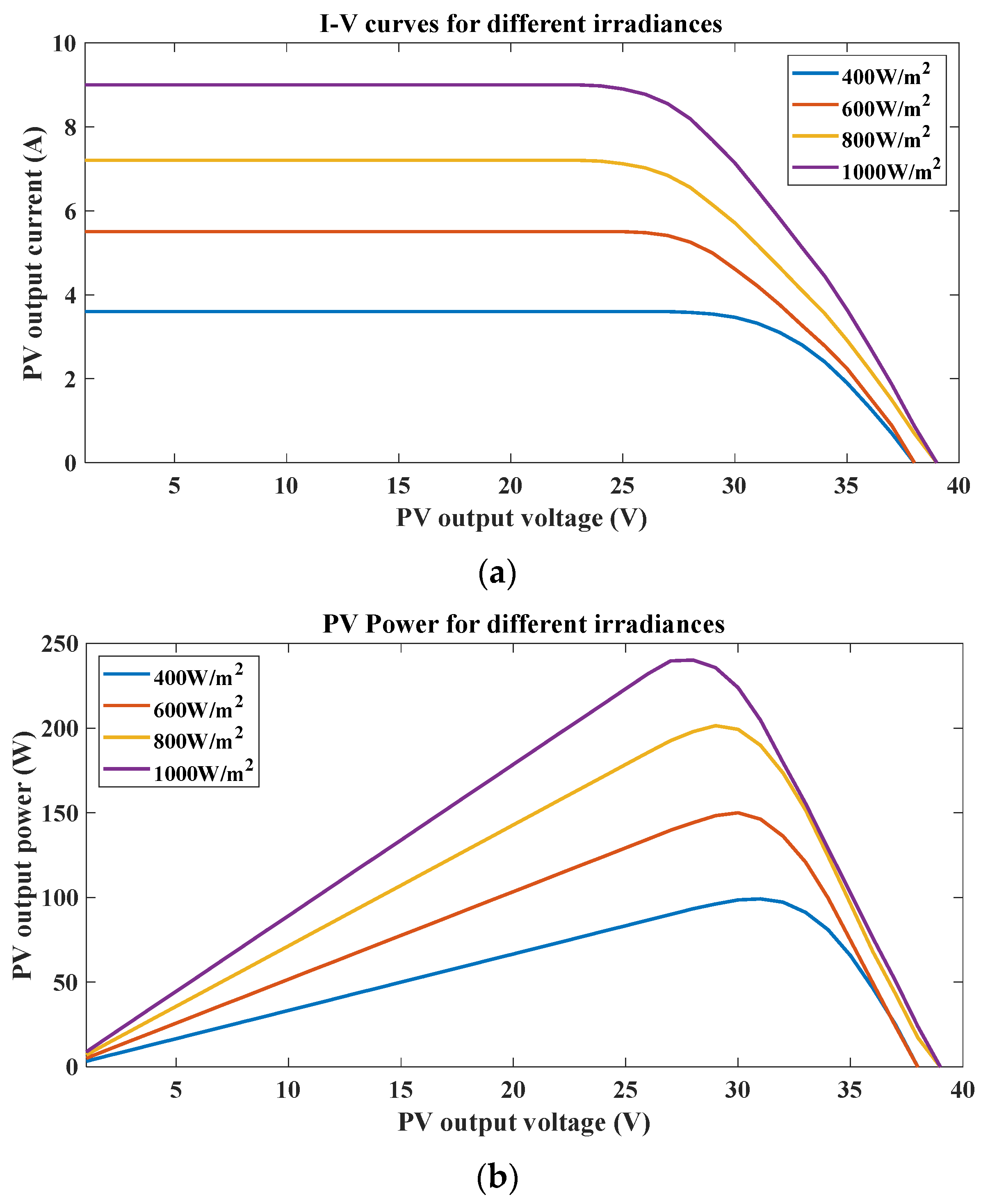
Figure 2a,b show the simulated I−V and P−V characteristics of the ideal PV panels, respectively. The series of curves show the output characteristics under different levels of illumination [14,16].
In MPPT control, it is desired to operate the PV system at knee point of Figure 2a corresponding to the peak point of Figure 2b for which the following expression holds:
P P V V P V = V P V I P V V P V = V P V I P V V P V + I P V V P V V P V = 0
In the proposed grid-connected PV system, the PV output voltage and current values are used to calculate P P V which is desired to be at maximum value. As opposed to methods like P&O, the changing rate in DC power to voltage ( P P V / V P V ) or current ( P P V / I P V ) can be used as an indicator of the PV array operating point, which, according to Equation (1), equals zero at the maximum power point (MPP). P P V / V P V can be calculated using samples from output active power and DC voltage [17].
The objective of the controller is to keep P P V / V P V at or near zero (or to keep I P V / V P V equal to I P V / V P V ). Figure 3 illustrates the control circuitry of the PV system introduced in Figure 1. The PI controller 1 is tuned to keep P P V / V P V near zero and thus track the maximum power point. Moreover, the injected reactive power, as obtained from output voltage and current values ( v c and i c ), is sampled by the respective control loop and regulated based on the specified Q r e f value. This control loop can be modified, in terms of PI controller gains, to also track the reference point of common coupling (PCC) voltage. Controller gains can be obtained using different methods [10].
The proportional hysteresis band controller (PHBC) helps in maintaining DC voltage within an acceptable level, which can be predetermined based on the PV system settings and grid requirements, and is discussed fully in the next section.

3. Proportional Hysteresis Band Controller

Operating around MPP makes PV DC voltage in single-stage PV systems very vulnerable to radiation and network disturbances. Situations like sudden radiation change or a change in voltage and reactive power reference values may cause the DC voltage to drop. If the PV inverter real power output is not decreased below the PV array output power very quickly, the capacitor will further discharge and the operating point on the P-V curve drops further down on the left side of the MPP and eventually the PV DC voltage drops to an unacceptable level before it starts to increase.
Due to the relatively slow speed of the MPPT PI controller, DC voltage drop is usually inevitable and therefore a fast method of correction in PWM phase shift becomes necessary to maintain a stable DC voltage [1,6]. A proportional HBC is used in this study to take this necessary correction measure to move the PV operating point back to the voltage source region. Contrary to typical hysteresis band controllers, which apply fixed controller gains during two certain modes of operation, proportional HBC introduced in this paper has variable gains for the two modes. 
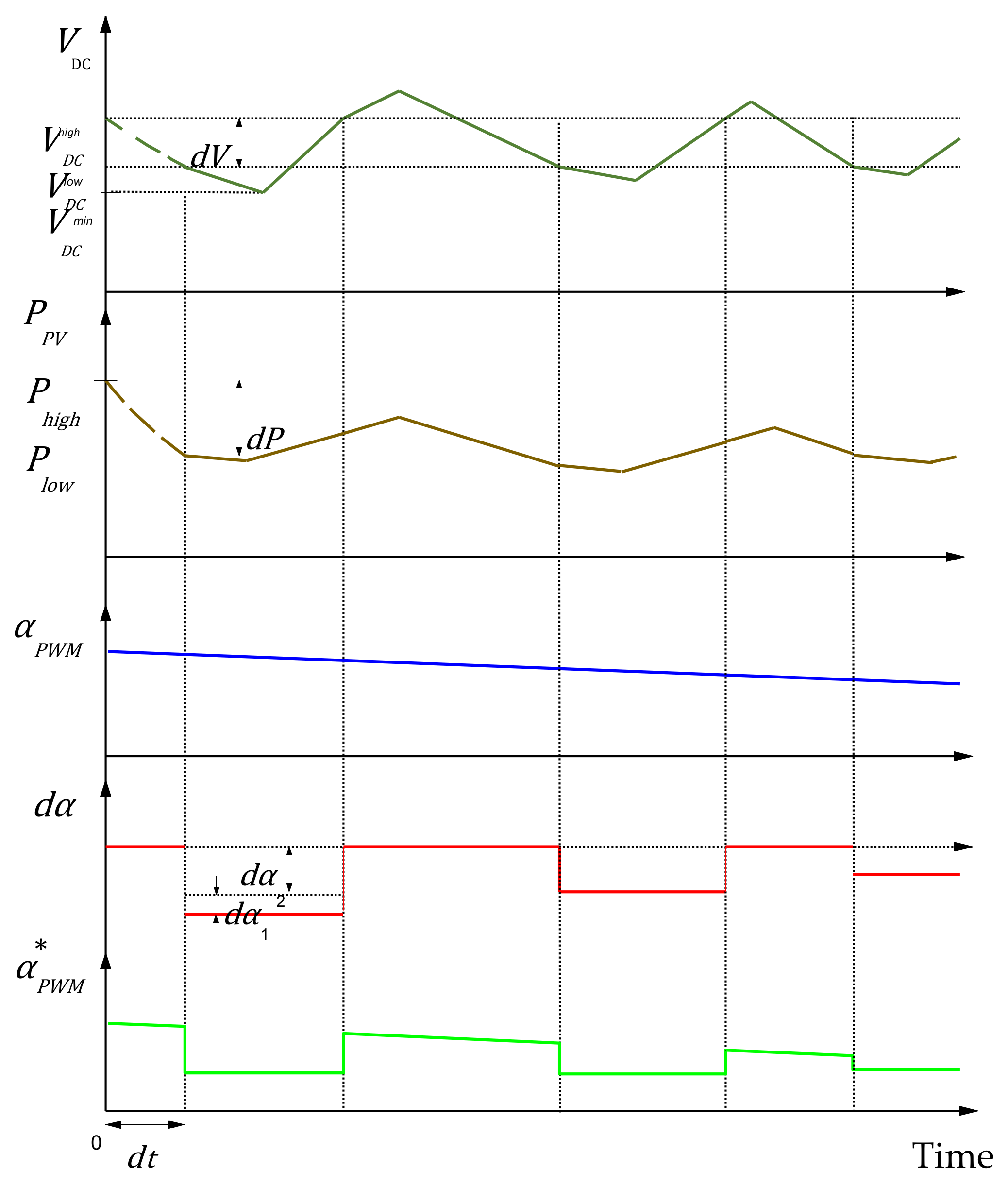
Figure 4 shows how this controller drives the PV DC-link voltage into a steady state voltage source region by changing the phase shift correction value in accordance with the rate of DC voltage drop in the capacitor as well as the PV’s active power drop. As the DC voltage of the PV system sinks below a predetermined value, the controller applies a coefficient, 0 < k 1 < 1.0 to the PWM phase shift so as to lower the phase shift instantly and thus limit the amount of injected active power to the grid. The capacitor will therefore have time to be charged back to the normal level. The coefficient applied to the phase shift will not be reset until the DC voltage exceeds the predetermined maximum level. The higher the rate of voltage drop in the DC-link capacitor and PV active power output, the larger the correction term applied to the PI controller phase shift output and the sharper the overall drop of PWM phase shift will be, hence yielding greater energy saving for the capacitor to charge back to normal level.
The PV output active power decreases as the DC-link voltage drops. In order to have a stable DC voltage, the balance of energy between the PV input and its output to the grid shall be maintained at all times. Accordingly, the reduction in PWM phase shift should necessarily be large enough to compensate for the capacitor voltage drop as well as to reduce the prospective output active power to where it has reached by the time it crosses V D C l o w level. Thus, the portion ( Δ α ) to be deducted from the initial PWM phase shift is composed of two parts: the first part is for compensation of the DC voltage ( Δ α 1 ), and the second part is for lowering the output active power by the amount that it has dropped ( Δ α 2 ).

3.1. DC Voltage Compensation Term

Energy stored in the DC-link capacitor during normal operation should always be maintained. Suppose a DC voltage disruption occurs in the PV system which causes DC-link voltage to drop from V 1 to V 2 . In order to make up for the lost energy, which has been injected to the grid in excess of the PV’s maximum output power, a tightening of the PWM reference phase shift is required during the prospective period that this voltage drop was going to happen.
1 2 C V 2 2 V 1 2 = V i n v V G X l Δ α 1 Δ t
where V i n v is the rms output voltage of inverter, V G is the rms grid voltage, C is the DC-link capacitance, and V 1 and V 2 are, respectively, the initial and final expected capacitor voltages during DC-link voltage collapse. Δ α 1 is the amount of change in the PWM phase shift and Δ t is the required time interval to apply Δ α 1 in order to avoid DC voltage drop. In the most severe condition, V 2 can be taken equal to be zero, assuming voltage collapse will continue until the complete discharge of the DC-link capacitor.
The output of inverter voltage is related to the modulation index m a and the DC-link voltage [30]:
V i n v = f m a V D C
where f m a is the ratio of the fundamental output of the inverter to the amplitude of the source voltage. For m a = 1.0 , this ratio equals 3 / 2 2 0.612 [31,32]. Therefore, for the fundamental component of the inverter output voltage, the following expression holds:
V i n v = V i n v 1 = 3 2 V D C 2 0.612 V D C
where V i n v 1 is the fundamental component of inverter output voltage. Higher-order components are ignored, assuming proper sizing of the LC or LCL filter.
Due to varying characteristics of V D C during voltage collapse, it can be expressed as a mean value between the initial and final values V 1 and V 2 , respectively:
V D C V 1 + V 2 2
Combining Equations (4) and (5) into (2) yields:
1 2 C V 2 V 1 = 0.612 V G 2 X l Δ α 1 Δ t
Simplifying Equation (6) and rearranging for the PWM phase shift will result in:
α = C V 2 V 1 X l 0.612 V G Δ t
Voltage changes in the DC-link capacitance can be detected by an approximate (difference) equation:
V = V t = V t V t T s T s
where T s is the DC voltage sampling period.
The value of V , as defined in Equation (8), is used to replace V 2 V 1 / Δ t in Equation (7). Hence, the required correction to the phase shift of voltage source converter in Equation (7) can be expressed as:
Δ α 1 = C V X l 0.612 V G
Equation (9) shows that the DC compensation term in phase shift reduction is proportional to the rate of voltage change and lowering the phase shift by this amount will compensate DC voltage variations in DC-link capacitor commensurately.

3.2. Active Power Output Correction Term

Upon DC voltage drop from V D C h i g h to V D C l o w , the output active power will also drop. This power has also been injected to the grid in excess of the input amount and therefore it shall be trimmed. The active power output correction term is related to the active power drop as follows:
Δ P = P h i g h P l o w = 0.612 V D C V G X l Δ α 2
where P h i g h and P l o w are the PV output power when DC voltage is V D C h i g h and V D C l o w , respectively. Δ P can also be expressed as:
Δ P = P t Δ t
where Δ t is the same as in Equation (2) and is defined as:
Δ t = t V Δ V = 1 V t Δ V = 1 V V h i g h V l o w
Combining Equations (11) and (12), Δ P is obtained as:
Δ P = P V V h i g h V l o w
and inserting Equation (13) into (10) results in:
P V V h i g h V l o w = 0.612 V D C V G X l Δ α 2
Rearranging for Δ α 2 yields
Δ α 2 = P V V h i g h V l o w X l 0.612 V D C V G
P / V is calculated through taking samples from power and voltage quantities, as discussed previously, and V D C h i g h and V D C l o w are set according to the design requirements. V D C is taken slightly below V D C l o w to account for a small further drop in DC voltage before the compensation takes effect.
Hence, the overall phase shift reduction is the sum of DC voltage compensation and active power correction terms:
Δ α = Δ α 1 + Δ α 2
where Δ α is the amount of reduction in phase shift upon observing the unstable DC voltage condition. The final PWM phase shift applied to the inverter becomes:
α P W M = α i n i Δ α
where α i n i and α P W M are the initial (uncorrected) and final PWM phase shift, respectively. It should be noted that α P W M as obtained above will prevent a DC voltage drop below V D C l o w . Therefore, in order to raise the DC voltage level back to V D C h i g h , the phase shift shall be slightly below α P W M . The α P W M 
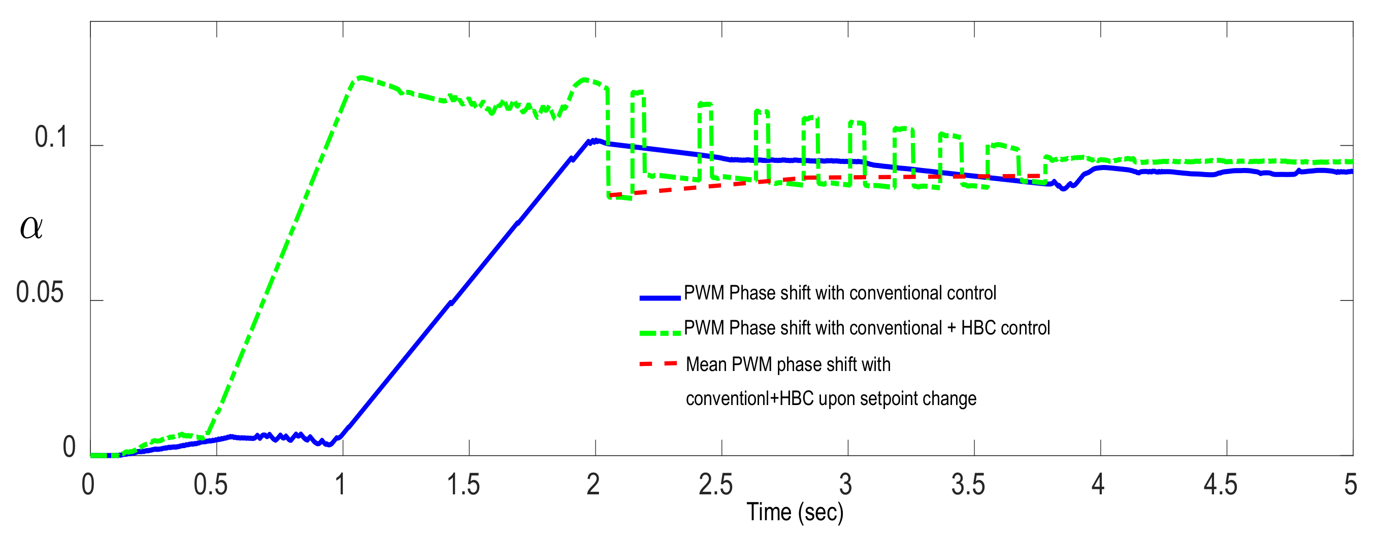
evolution is visually depicted in Figure 5.

4. Simulation Results

The proposed method is used to control the DC-link voltage level in three major modes. The first is MPPT mode when the PV system is connected to the grid. MPPT with VAR tracking is taken as the second test case and for the third case, MPPT with voltage regulation mode is considered. PWM phase shift correction is calculated based on instantaneous voltage and power values and system parameters (as given in Appendix A). The sampling period is taken as T s = 1   ms and simulations are performed using MATLAB-Simulink™ software. As a general observation in all cases, the PWM phase shift in the absence of hysteresis controller reacts relatively slowly to the drop in DC voltage and active power output as shown in Figure 6. However, by using the hysteresis controller, besides having an overall fast response, the phase shift will change in a stepwise manner which becomes steadily smaller until the steady value of the phase shift is reached. As depicted by dashed lines, the mean phase shift value during the transition between setpoints is lower with the proposed control approach as compared to conventional control. This contributes to the DC-link voltage stability as demonstrated in the following study cases.

4.1. MPPT Mode

As a base case, the PV system performance in MPPT is studied. Although a change in radiation level is usually slow enough to allow for the controller to adjust the power output level, here a step change in radiation level is introduced to represent any kind of interruption on the DC-link voltage level either internally or imposed by the grid. The reactive power injected to the grid is zero and grid voltage is steady at 380 V. A radiation change occurs from 1000 to 800 W/m2 at t = 1.2   s . The conventional MPPT controller’s output and the respective output power and DC voltage level are shown in Figure 7a. As shown, the DC-link capacitor experiences a great voltage drop from 650 V down to below 100 V before it starts to recharge. This is attributed to the fact that the amount of power delivered to the grid is beyond the rate of DC-link capacitor charge recovery, which has been weakened due to lower irradiance levels. The conventional PI controller employed in this case cannot provide as fast a response to this step change to avoid the tremendous DC-link voltage drop.
With the proposed proportional hysteresis band controller, however, the PWM phase shift is adjusted in proportion to the drop in active power and DC-link voltage drop rate and compensation is achieved, immediately resulting in steady DC-link voltage, as shown in Figure 7b. Due to the appropriate gain of hysteresis band controller, the steps in phase shift correction are eventually reduced as per Figure 7b until a stable DC voltage is reached.

4.2. MPPT and PCC Voltage Reference Tracking

The PV system may be asked by Microsource Controllers in microgrids to track a reference PCC voltage. Figure 8a,b show system performance in the absence and presence of the hysteresis controller effect, respectively. There is an increase in reference PCC voltage at t = 3   s from 1.0 to 1.02 pu, that is, from 380 Vrms to about 388 Vrms (line voltage). This will entail the PV system increasing the injected reactive power to PCC.
As seen in Figure 8a with the conventional PI controller, no matter how finely the controller has been tuned, great voltage sag will occur, resulting not only in severe distortion in the output active power and current, but also absorption of a tremendous amount of reactive power from the grid before it starts to increase injected reactive power. Figure 8b shows the improved situation using the proposed proportional hysteresis band controller. The maximum ripple in the injected active power is reduced to less than 2 kW compared to more than 5 kW in the conventional control. Other advantages offered by this approach include the reduction in reactive power fluctuation, as in the transient situation the PV system absorbs a great amount of reactive power from the grid due to the low DC voltage.
Here, by maintaining the DC-link voltage above 550 V, this problem is alleviated. Considering the reduced fluctuations in the PV output quantities, output filter size and cost can also be reduced. It is also worth noting that the settlement time with the conventional control is higher than that with the proposed hysteresis band controller. As is evident in Figure 8b, the PCC voltage has just settled on 388 V within 7 s from the reference change. However, as is observed in Figure 8a, the PCC voltage is equal to 400 V after 7 s and it will take longer for the PCC voltage to come down to 388 V with the conventional method.

4.3. MPPT and VAR Tracking Model (Real-Time Scenario)

In this study, the PV system with the proposed control method is implemented in the real-time simulator, OPAL-RT-OP5600, to verify its applicability and effectiveness in real time. Figure 9 shows the broad configuration of the experimental setup. Figure 10a,b show the PV system’s DC voltage and active and reactive power variation in MPPT and VAR tracking mode without and with the hysteresis band controller, respectively. A step change is applied to reactive power reference from 3 kVAR to 10 kVAR in t = 2   s . As shown in Figure 10a, in the absence of the hysteresis band controller, DC voltage is decreased to a very low value before returning to the normal level, causing a severe fluctuation in the active and reactive power injected to the grid.
With the proportional hysteresis band controller (PHBC), however, the DC fluctuation is confined to less than 80 V (0.2 pu) as shown in Figure 10b and therefore, the active and reactive power distortion is considerably controlled.
As observed, the proposed control strategy functions reliably well in different PV operating modes. The term Δ α 2 in Equations (15) and (16) ensures enough reduction in phase shift α that a rise in V D C to above V D C h i g h is guaranteed. This makes for a robust supplemental control compared to other methods already in use.
In [7], a correction term is applied to PWM phase shift whenever the value of P / V goes beyond a certain level. The proposed method here, however, allows for the normal control to perform its function during normal operation. The supplementary PHBC comes into action only when the DC voltage falls below a predetermined value, thus allowing for a much faster control operation with minimum interference with the normal control circuit in normal operation conditions. Further, since the approach in [7] mainly relies on a simple proportional correction term, the resulting PWM phase shift and therefore the output voltage and current quantities are distorted due to the fluctuating nature of P / V . This may not yield satisfactory results for all possible modes of operation and with any degree of interruption. For instance, the system does not respond as well in PCC voltage control as it does in VAR tracking mode, with a fixed controller proportional gain. So, it will need the proportional gain tuning for each mode and degree of transient severity. The proposed method, however, is based on the DC voltage limits and yields relatively smooth waveforms due to the fixed PWM phase shifts with a trivial output ripple that can be eliminated by proper output filter sizing.

4.4. Inverter Power Output Effect on DC-Link Voltage

As witnessed, operation in MPPT mode is a common goal of the control module for all considered cases. The interaction between DC voltage control and the maximum power generation is an interesting feature involved in these study cases. As observed, upon the step changes introduced into different scenarios, including the changes applied to the irradiation level and the reactive power setpoint, the proposed HBC module temporarily prevails upon the maximum power tracking for a short duration in order to prevent a further drop in DC-link voltage. As demonstrated in Figure 8b and Figure 10b, this action also leads to a more consistent power output profile besides avoiding DC-link voltage collapse. The result is indeed an improved transient state upon setpoint changes. After stabilization, the MPPT operation is resumed and the HBC controller automatically becomes inactive. This unique coupling between the MPPT control and DC-link voltage control is a major feature of the proposed approach.
The proposed approach is well-suited for PV connection to infinite grids where the voltage sourced inverter is mainly involved in maintaining a steady active and/or reactive power supply to the grid. Moreover, as demonstrated in Figure 8, the system performance is deemed acceptable for moderate changes in PCC voltage which is typical of weak grids. In the case of connection to grids with higher voltage fluctuations, maintaining a steady voltage at the inverter’s output may require a more sophisticated control mechanism by the inverter controller such that all control objectives including maximum power delivery, stable DC-link voltage, and stable voltage at the inverter output terminals are met.

5. Conclusions

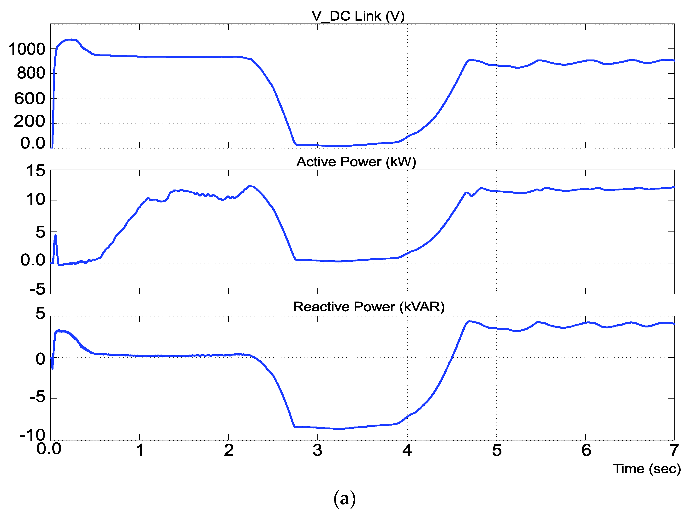
In this paper, a new approach based on PHBC is introduced to ensure the stability of DC-link voltage in grid-connected PV systems. By effectively combining the hysteresis band controller module with the main MPPT controller, a fast correction is made to the reference phase shift of the PV inverter’s PWM generator when the PV operation point moves to the current source region. As demonstrated by the simulation and experimental results, besides improving DC voltage stability, the transient conditions in terms of active and reactive power and current injection to the grid are improved. The system also reaches the steady state through shorter and less volatile transients than with the conventional control methods. Simulation results for different operating regimes including MPPT mode, MPPT+VAR control mode, and MPPT+PCC voltage control mode indicate the proficiency of the proposed approach and the steady operation of the PV system against a diverse set of exogenous disturbances. Thus, the proposed approach can be regarded as an efficient and cost-effective tool to ensure the stability of DC-link voltage in single-stage solar PV systems for different operating modes.
As discussed, further studies can examine the extent to which the proposed control mechanism can be stable against significant PCC voltage fluctuations and further control strategies thereof. Moreover, work on sensorless control methods in combination or as backup strategies for the proposed approach can be tremendously valuable. Further, considering other uncertainties including the ambient temperature fluctuations, possible filtering impacts, etc., can also be considered in future works.

Author Contributions

Conceptualization, H.K., A.O. and A.A.-M.; methodology, H.K.; software, H.K. and A.O.; validation, A.O. and A.A.-M.; formal analysis, H.K. and A.O.; investigation, A.A.-M.; resources, H.K.; data curation, H.K. and A.O.; writing—original draft preparation, H.K.; writing—review and editing, A.O. and A.A.-M.; supervision, A.A.-M. All authors have read and agreed to the published version of the manuscript.

Funding

This research received no external funding.

Conflicts of Interest

The authors declare no conflict of interest.

Appendix A

Parameters used in this study for single-stage PV system and electrical grid are presented in Table A1, Table A2 and Table A3:
Table A1. PV array parameters.
Number of cells in series N s = 44
Number of cells in parallel N p = 5
Internal Series Resistance R s = 0.47   Ω
Cell voltages V O C = 23   V ,   V M P P = 17   V
Switching circuit parameters:
PWMThree-phase, six pulse
Switching Frequency f s w = 2   kHz
Modulation Index m a = 1.00
DC-link capacitor parameters:
Capacitance C 1 = 400   μ F
HBC reset voltage V D C h i g h = 650   V
HBC activation voltage V D C l o w = 600   V
Minimum Acceptable DC-link voltage V D C m i n
Filter Inductance L F = 5   mH
Filter Capacitance C F = 65   μ F
Table A2. Grid parameters.
Line to Line Voltage V l = 380   V r m s
Frequency f = 50   Hz
Short-Circuit Power S s c = 100   kVA
Reactance to Resistance Ratio X / R = 5
3-Phase load parameters 10   kW , 1   kVAR , lag
Table A3. PI controller gains.
KpKI
MPPT Control 2 × 10 14 2 × 10 5
Reactive Power Control 2 × 10 7 2 × 10 5
PCC Voltage Control 2 × 10 2 1.5 × 10 2

References

  1. Oshnoei, S.; Aghamohammadi, M.; Oshnoei, S.; Oshnoei, A.; Mohammadi-Ivatloo, B. Provision of Frequency Stability of an Islanded Microgrid Using a Novel Virtual Inertia Control and a Fractional Order Cascade Controller. Energies 2021, 14, 4152. [Google Scholar] [CrossRef]
  2. Lee, J.; Bérard, J.P.; Razeghi, G.; Samuelsen, S. Maximizing PV hosting capacity of distribution feeder microgrid. Appl. Energy 2020, 261, 114400. [Google Scholar] [CrossRef]
  3. Sasidharan, N.; Singh, J.G. A resilient DC community grid with real time ancillary services management. Sustain. Cities Soc. 2017, 28, 367–386. [Google Scholar] [CrossRef]
  4. Gawhade, P.; Ojha, A. Recent advances in synchronization techniques for grid-tied PV system: A review. Energy Rep. 2021, 7, 6581–6599. [Google Scholar] [CrossRef]
  5. Nyholm, E.; Odenberger, M.; Johnsson, F. An economic assessment of distributed solar PV generation in Sweden from a consumer perspective—The impact of demand response. Renew. Energy 2017, 108, 169–178. [Google Scholar] [CrossRef]
  6. Ma, L.; Liu, N.; Wang, L.; Zhang, J.; Lei, J.; Zeng, Z. Multi-party energy management for smart building cluster with PV systems using automatic demand response. Energy Build. 2016, 121, 11–21. [Google Scholar] [CrossRef]
  7. Ranamuka, D.; Agalgaonkar, A.P.; Muttaqi, K.M. Conservation voltage reduction and VAr management considering urban distribution system operation with solar-PV. Int. J. Electr. Power Energy Syst. 2019, 105, 856–866. [Google Scholar] [CrossRef]
  8. Adhikari, S.; Li, F. Coordinated V-f and P-Q Control of Solar Photovoltaic Generators With MPPT and Battery Storage in Microgrids. IEEE Trans. Smart Grid 2014, 5, 1270–1281. [Google Scholar] [CrossRef]
  9. Maknouninejad, A.; Kutkut, N.; Batarseh, I.; Qu, Z. Analysis and control of PV inverters operating in VAR mode at night. ISGT 2011, 15, 142. [Google Scholar]
  10. Liang, W.; Liu, Y.; Peng, J. A Day and Night Operational Quasi-Z Source Multilevel Grid-Tied PV Power System to Achieve Active and Reactive Power Control. IEEE Trans. Power Electron. 2021, 36, 474–492. [Google Scholar] [CrossRef]
  11. Mulolani, F.; Armstrong, M.; Zahawi, B. Modeling and simulation of a grid-connected photovoltaic converter with reactive power compensation. Int. Symp. Commun. Syst. Netw. Digit. Sign 2014, 11, 888–893. [Google Scholar]
  12. Chandrareddy, E.S.; Chengaiah, C.; Bullarao, D. A100 kw single stage grid-connected PV system with controlled DC-link voltage. Mater. Today Proc. 2021, 12, 452. [Google Scholar] [CrossRef]
  13. Kadri, R.; Gaubert, J.; Champenois, G. An Improved Maximum Power Point Tracking for Photovoltaic Grid-Connected Inverter Based on Voltage-Oriented Control. IEEE Trans. Ind. Electron. 2011, 58, 66–75. [Google Scholar] [CrossRef]
  14. Li, H.; Xu, Y.; Adhikari, S.; Rizy, D.T.; Li, F.; Irminger, P. Real and reactive power control of a three-phase single-stage PV system and PV voltage stability. 2012 IEEE Power Energy Soc. Gen. Meet. 2012, 11, 245. [Google Scholar]
  15. Yeganeh, M.S.O.; Mijatovic, N.; Dragicevic, T. Dynamic Performance Optimization of Single-Phase Inverter based on Model Predictive Control. IEEE Int. Conf. Predict. Control Electr. Drives Power Electron. 2021, 11, 235–240. [Google Scholar]
  16. Guo, B. Optimization Design and Control of Single-Stage Single-Phase PV Inverters for MPPT Improvement. IEEE Trans. Power Electron. 2020, 35, 13000–13016. [Google Scholar] [CrossRef]
  17. Koutroulis, E.; Blaabjerg, F. Design Optimization of Transformerless Grid-Connected PV Inverters Including Reliability. IEEE Trans. Power Electron. 2013, 28, 325–335. [Google Scholar] [CrossRef]
  18. Raj, A.; Arya, S.R.; Gupta, J. Solar PV array-based DC–DC converter with MPPT for low power applications. Renew. Energy Focus 2020, 34, 109–119. [Google Scholar] [CrossRef]
  19. Yeganeh, M.S.O.; Sarvi, M.; Blaabjerg, F.; Davari, P. Improved harmonic injection pulse-width modulation variable frequency triangular carrier scheme for multilevel inverters. IET Power Electron. 2020, 13, 3146–3154. [Google Scholar] [CrossRef]
  20. Yeganeh, M.S.O.; Davari, P.; Chub, A.; Mijatovic, N.; Dragicevic, T.; Blaabjerg, F. A Single-Phase Reduced Component Count Asymmetrical Multilevel Inverter Topology. IEEE J. Emerg. Sel. Top. Power Electron. 2021, 9, 6780–6790. [Google Scholar] [CrossRef]
  21. Hossain, M.A.; Pota, H.R.; Haruni, A.M.O.; Hossain, M.J. DC-link voltage regulation of inverters to enhance microgrid stability during network contingencies. Electr. Power Syst. Res. 2017, 147, 233–244. [Google Scholar] [CrossRef]
  22. Libo, W.; Zhengming, Z.; Jianzheng, L. A Single-Stage Three-Phase Grid-Connected Photovoltaic System With Modified MPPT Method and Reactive Power Compensation. IEEE Trans. Energy Convers. 2007, 22, 881–886. [Google Scholar] [CrossRef]
  23. Hornik, Q.C.Z.T. Control of Power Inverters in Renewable Energy and Smart grid Integration, 1st ed.; John Wiley & Sons: Hoboken, NJ, USA, 2013. [Google Scholar]
  24. Davoodnezhad, R.; Holmes, D.G.; McGrath, B.P. A Novel Three-Level Hysteresis Current Regulation Strategy for Three-Phase Three-Level Inverters. IEEE Trans. Power Electron 2014, 29, 6100–6109. [Google Scholar] [CrossRef]
  25. Kumar, V.; Singh, M. Sensorless DC-link control approach for three-phase grid integrated PV system. Int. J. Electr. Power Energy Syst. 2019, 112, 309–318. [Google Scholar] [CrossRef]
  26. Afrin, N.; Yang, F.; Lu, J. Voltage support strategy for PV inverter to enhance dynamic voltage stability of islanded microgrid. Int. J. Electr. Power Energy Syst. 2020, 121, 106059. [Google Scholar] [CrossRef]
  27. Merai, M. A systematic design methodology for DC-link voltage control of single phase grid-tied PV systems. Math. Comput. Simul. 2020, 11, 245. [Google Scholar] [CrossRef]
  28. Lam, C.; Wong, M.; Han, Y. Hysteresis current control of hybrid active power filters. IET Power Electron. 2012, 5, 1175–1187. [Google Scholar] [CrossRef] [Green Version]
  29. Wu, L.; Zhao, Z.; Liu, J. Intelligent controller for photovoltaic lighting systems. J.-Tsinghua Univ. 2003, 43, 1195–1198. [Google Scholar]
  30. Chen, K.; Zhao, Z.; Yuan, L. Implementation of a stand-alone photovoltaic pumping system with maximum power point tracking. In Proceedings of the Fifth International Conference on Electrical Machines and Systems (IEEE Cat. No.01EX501), Shenyang, China, 18–20 August 2001. [Google Scholar]
  31. Skvarenina, T.L. The Power Electronics Handbook; CRC Press LLC: New York, NY, USA, 2002. [Google Scholar]
  32. Krause, P.C.; Wasynczuk, O.; Sudhoff, S.D.; Pekarek, S.D. Analysis of Electric Machinery and Drive Systems; Wiley-IEEE Press: Piscataway, NJ, USA, 2002. [Google Scholar]
Figure 1. Grid-connected single-stage PV system configuration.
Electronics 11 00452 g001
Figure 2. (a) I-V curve of ideal PV panel; (b) P-V curve of ideal PV panel.
Electronics 11 00452 g002
Figure 3. Proposed control block diagram of the PV system.
Electronics 11 00452 g003
Figure 4. Proportional HBC.
Electronics 11 00452 g004
Figure 5. DC voltage, active power, PWM phase shift, HBC output, and overall phase shift.
Electronics 11 00452 g005
Figure 6. PWM phase shift during disturbance with conventional control vs. proposed control scheme.
Electronics 11 00452 g006
Figure 7. DC voltage and output active power with step change in radiation from 1000 to 800 W/m2 at t = 1.2 s with: (a) conventional control and (b) proportional HBC.
Electronics 11 00452 g007aElectronics 11 00452 g007b
Figure 8. VPCC control with: (a) conventional controller and (b) proportional HBC. VPCC reference is changed from 1.0 to 1.02 pu at t = 3   s .
Electronics 11 00452 g008
Figure 9. Real-time experimental setup.
Electronics 11 00452 g009
Figure 10. DC voltage and active and reactive power variation in VAR tracking mode with step change in reference reactive power at t = 2 s from 3 kVAR to 10 kVAR using: (a) conventional control; and (b) proportional HBC.
Electronics 11 00452 g010aElectronics 11 00452 g010b
Publisher’s Note: MDPI stays neutral with regard to jurisdictional claims in published maps and institutional affiliations.

