Article

Multiple-Intelligent Reflective Surfaces (Multi-IRSs)-Based NOMA System

by
Ziad Qais Al-Abbasi
1,*,†,
Laith Farhan
2,† and
Raad S. Alhumaima
3,†
1
Middle Technical University (MTU), Baquba Technical Institute, Baghdad 10001, Iraq
2
Department of Computer, College of Engineering, University of Diyala, Baqubah 32001, Iraq
3
Department of Communications, University of Diyala, Baqubah 32001, Iraq
*
Author to whom correspondence should be addressed.
These authors contributed equally to this work.
Electronics 2022, 11(23), 4045; https://doi.org/10.3390/electronics11234045
Submission received: 5 October 2022 / Revised: 17 November 2022 / Accepted: 17 November 2022 / Published: 6 December 2022

Abstract

:
Recent research has introduced the notion of an Intelligent Reflective Surface (IRS) so as to boost the source–destination communication environment. IRS refers to a plane that consists of a number of passive elements that have a smaller size than the wavelength of the incident signal. Those elements use reflection to beam-form and to forward the incident radio signals toward the intended destination without power consumption. This article examines the performance of an IRS-based non-orthogonal multiple access (NOMA) system, and adopts the idea of using multiple IRS planes. It additionally investigates improving the performance of an IRS-NOMA combination through proposing various solutions that include optimizing the overall number of the IRS elements as a first step. After that, a closed form expression is derived for the considered IRS-NOMA system to determine the optimal number of the reflective elements. Secondly, the paper utilizes a new approach termed as multiple-IRS-based NOMA. This encompasses using multiple reflective planes (multi-IRS) along with IRS-NOMA, to boost the received signal characteristics, especially in situations where it is there a weak or no direct link between the source and the destination. An energy efficiency-spectral efficiency (EE-SE) trade-off is likewise presented, so as to have a complete view of the IRS-NOMA performance, along with the proposed solutions. The obtained simulation results depicts that IRS-NOMA is better than the existing orthogonal techniques. In addition, the results confirm that exploiting multiple IRSs offers a considerable gain in performance, as it enhances the conditions of the propagation environment. In specific, the considered case of a two IRS surfaces-assisted NOMA system offers higher performance levels than the case of a single IRS surface-assisted NOMA system.

1. Introduction

The prediction regarding the next generations of wireless networks is that it would require a massive traffic demand, high connectivity, and high efficiency with regard to both energy and spectral aspects [1]. As a solution, non-orthogonal multiple access (NOMA) has been presented as a promising technology to fulfil such requirements due to its efficient spectrum use. NOMA permits all users to share the same frequency resource, which improves the spectral efficiency and also reduces latency by allowing all users to instantly use the same time-slot [1,2,3]. Several existing literature works, i.e., refs. [1,2,4,5,6,7,8,9,10,11,12] have explored different aspects of NOMA potential and their outcomes have approved its effectiveness, especially against its orthogonal predecessors. NOMA has proven its vitality to be adapted as a future air interface as a stand-alone, or even in combination with existing techniques such as multi-input multi-output (MIMO) [6,13,14] and device-to-device (D2D) communications [4,15,16]. The mechanism of NOMA is that at the source, it manages the power allocation among its users using a superposition coding technique that exploits the differences in their channel gains. At the destination, all users apply successive interference cancellation (SIC) so that each one can decode its respective data message [1,2,3].
Nevertheless, the achievable spectral efficiency (SE) and energy efficiency (EE) of existing wireless networks could be enhanced further by deploying software-controlled reflecting surfaces known as intelligent reflective surfaces (IRSs). As can be seen in Figure 1, the IRS surface is formed by a large number of passive reflecting elements, where each element is capable of changing the phase shift of the incident signal to be reflected towards the receiving destination [17,18]. Lately, a combination of NOMA empowered with IRS has emerged as a promising and cost effective solution to boost both SE and EE, as well as to increase the probability of successful reception in wireless networks. This is possible as the IRS modifies the propagation environment in such a way that strengthens the received signal by the users, as shown in Figure 1, particularly in situations where those environments are characterized by obstacles and/or have a weak direct path between the source and the destination [19].
A number of literature works have already presented the IRS and have examined its prospects and applicability, and this paper is an effort in the same direction. The IRS potential allows its integration with several existing technologies such as the single-input, single-output (SISO) system, MIMO system, NOMA, and others. For example, the authors of [20] addressed the performance gain of combining IRS and a millimeter-wave (mmWave) communication system through optimizing the phases of the transmitted signals. The authors of [21] addressed the performance of IRS as compared to the with classic decode-and-forward technique with no NOMA being taken into consideration. The authors concluded that for IRS to overcome the DF relaying performance, it requires large meta-surfaces and considerably high rates. Hence, such results form one of the reasons that encourage a study of the combination of NOMA with IRS to avoid using high rates and wide meta-surfaces. In addition, works such as ref. [17] investigated minimizing the transmission power of IRS-NOMA via joint optimization of the IRS-phase shift matrix and the transmission beam-former of the BS. Moreover, [22] considered optimizing the overall sum rate of IRS-NOMA through jointly optimizing the beam-forming at the BS and the IRS under the constraints of the decoding rate of the SIC, as well as the IRS reflecting elements. The authors in [23] presented an IRS-assisted downlink NOMA system and showed that the cooperation between IRS and NOMA can enhance the cell edge user’s experience. The authors in [24] addressed the effects of two phase shifting designs on the performance of IRS-NOMA in terms of complexity and reception reliability. The potential of IRS is even investigated in satellite networks [25,26,27,28]; for instance, the authors in [25] studied the application of IRS units to tackle the path loss results from the long transmission distances. The authors proved that IRS-assisted satellites can offer several thousand fold of the achievable rates for IoT networks in both uplink and downlink.
In this paper, one motivating idea behind adopting multiple IRSs is the outcomes that could be obtained, such as reducing the required numbers of the serving BS, and hence reducing the consumed transmission power and improving the energy efficiency. Moreover, having less BSs means less interference problems, which also nullify the need for interference cancellation techniques. Another motivation behind exploiting multiple IRSs is its ability to control the communication environment by using the transmitted signal’s phase and amplitude as a beam-forming to control and direct the reflection toward the receiver. IRS beam-forms the incident signals by nullifying the unwanted ones and strengthening the intended ones. IRS could also assist the BS transmission towards the cell-edge users, which represents a cost-effective solution as compared to other measures such as increasing the transmission power and placing extra BS at the cell boundaries. By controlling the communication environment, IRS could minimize the effect of channel randomness, boost the achievable capacity, and enhance the channel reliability. Nevertheless, this paper examines the performance of IRS-NOMA and proposes a number of solutions to boost its performance. First of all, it focuses on optimizing the number of reflecting elements in the IRS-NOMA system. The paper also proposes using multiple IRS-based NOMA systems to improve the quality of the received signal, and to overcome the limitations of a single IRS-based system. The EE–SE trade-off behavior is investigated to obtain a comprehensive view of the proposed solutions, along with the considered IRS-NOMA system, and all the comparisons throughout this paper included the orthogonal multiple access (OMA) system.
The rest of this paper is organized by presenting the considered IRS model in Section 2. Section 3 presents the derivation steps of the proposed optimal number of IRS elements. The proposed multiple IRS-based NOMA is explained in Section 4. The performed simulations and the obtained numerical results are presented in Section 5, and Section 6 lists the conclusions of the paper.

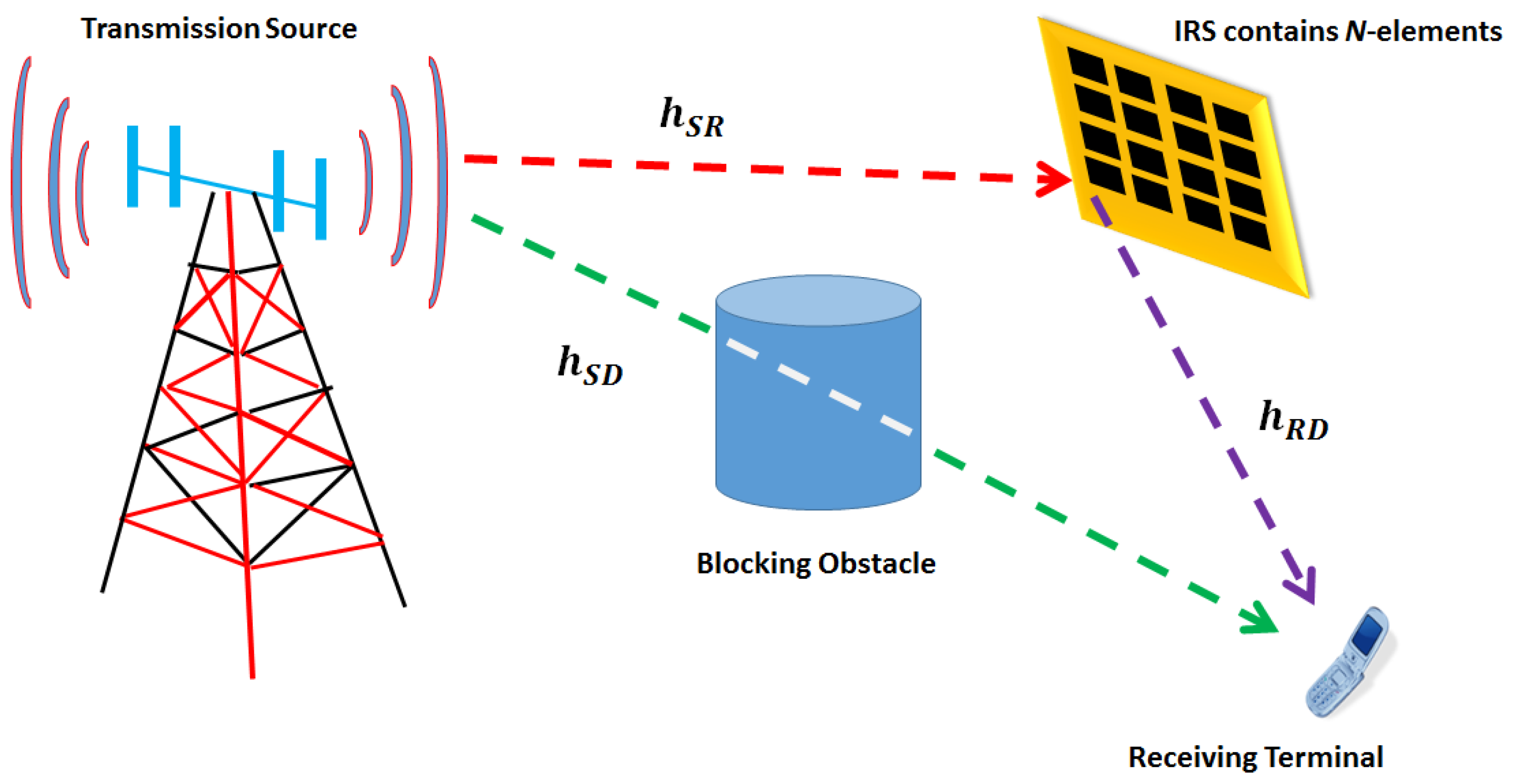
2. The Modeled IRS-NOMA System

The considered scenario is similar to the illustration in Figure 1. A downlink- communication system assisted with N-elements reflective plane is mode led, with both the source and the destination being considered to be equipped with single antennae. At the destination, the received signal is
y u = h S D u + h S R u T Θ h R D u P I R S u x u + n u
where h S D u C N denotes the flat fading channel gain between the source in the destination, while h S R u C N denotes that between the source and the IRS. In addition, h D R u C N and x u represent the channel gain between the IRS and the destination and the information signal, respectively. Moreover, Θ = α d i a g e j θ 1 , e j θ 2 , , e j θ N is a diagonal matrix and θ 1 , θ 2 , , θ N denotes the phase shift of the IRS elements with α ( 0 , 1 ] standing for a constant reflection coefficient; n u CN 0 , σ 2 stands for the noise at the receiver. As a milestone, IRS-OMA will be considered in this paper for a comparison against the proposed IRS-NOMA system. The achievable SE of the IRS-OMA system is
S E I R S O M A u = log 2 1 + P I R S O M A u h S D u z u
where P I R S O M A u and N denote the power assigned to the u-th user in IRS-OMA system and the total number of reflection elements, respectively. z u CN 0 , σ 2 is the additive white Gaussian noise (AWGN) that has a zero mean and a variance of σ 2 . The considered model assumes that the U-IRS-NOMA users are scheduled in descending order based on their channel power, then the achievable SE by the u-th user is
S E I R S N O M A u = log 2 1 + P I R S N O M A u h S D u + h S R u T Θ h R D u 2 ξ u + z u
where P I R S N O M A u denotes the power assigned to the u-th user in IRS-NOMA. ξ u = v = u + 1 U P I R S N O M A v h S D u + h S R u T Θ h R D u 2 represents the effect of other IRS-NOMA users that have a better channel gain than the u-th user, and they are multiplexed over the same resource, along with the u-th user. According to the SIC mechanism, each user will consider the other multiplexed peers with higher channel gains as noise, while they cancel the effect of the ones who have lower channel gains before decoding their own signal. Note that ξ u = 0 for the U-th indexed user case. Note that both P I R S O M A u and P I R S N O M A u are assumed to be allocated equally among all users following P I R S O M A u = P I R S N O M A u = P U , where P represents the total transmission power.
Knowing that h S R u T Θ h R D u = α n = 1 N e j θ n h S R u n h R D u n , beside the fact that (2) and (3) depend on the channel amplitudes rather than its phase, hence, it is possible to use the notation 1 N n = 1 N h S R u n h R D u n = Γ I R S u . The expressions in (2) and (3) could be rewritten as
S E I R S O M A u = log 2 1 + P I R S O M A u Γ S D u 2 z u
S E I R S N O M A u = log 2 1 + P I R S N O M A u Γ S D u + N α Γ I R S u 2 ξ u + z u
respectively. From (5), given that S E I R S N O M A u has a predetermined target value; then the required transmission power by the IRS-NOMA system could be obtained as
P I R S N O M A u N = 2 S E I R S N O M A u 1 z u + v = u + 1 U P I R S N O M A v Γ S D u + N α Γ I R S u 2 Γ S D u + N α Γ I R S u 2 .
On the other hand, the total power consumed by the IRS-NOMA system with N reflective elements is
P T o t c o n s N = N P E + P S + P D + P I R S N O M A u N η P A
where P E , P S , and P D denote the dissipated power by each reflective element, by the source, and destination, respectively, whilst the term η P A represents the efficiency of the power amplifier.

3. The Proposed Closed Form N Expression

One of the proposed solutions to improve the performance of IRS-NOMA is to find the optimal number of reflective elements. Optimizing the number of the reflective elements could also boost the spectral efficiency and help in reducing the required transmission power, which in turn, enhances the overall energy efficiency. The derivative of (6) with respect to N could be used as
d P I R S N O M A u d N = P E 2 α Γ I R S u 2 S E I R S N O M A u 1 ( v = u + 1 U P I R S N O M A v η P A Γ S D u + N α Γ I R S u + z u + v = u + 1 U P I R S N O M A v Γ S D u + N α Γ I R S u 2 η P A Γ S D u + N α Γ I R S u 3 ) .
On the other hand, to investigate the nature of P I R S N O M A u as a function of N, the second derivative is necessary, which is obtained to be
d 2 P I R S N O M A u d N 2 = 6 α 2 Γ I R S u 2 2 S E I R S N O M A u 1 [ z u + v = u + 1 U P I R S N O M A v Γ S D u + N α Γ I R S u 2 η P A Γ S D u + N α Γ I R S u 4 v = u + 1 U P I R S N O M A v η P A Γ S D u + N α Γ I R S u 2 ] ,
It is clear from (9) that d 2 P I R S N O M A u d N 2 >0; hence, the function has a convex nature. Obtaining the optimal N is possible by setting d P I R S N O M A u d N = 0 and solving for N to obtain
N I R S N O M A = 2 α Γ I R S u 7 P E 2 z u η P A 2 2 S E I R S N O M A u 1 3 α Γ I R S u 3 P E η P A ,
the subscript (   ) I R S N O M A is included for recognition between the IRS-NOMA and IRS-OMA parameters.
On the other hand, based on (2) and (7), the same procedure could be followed to obtain the optimized N in IRS-OMA case as
N I R S O M A = φ u 3 Γ S D u P E η P A 3 α Γ I R S u P E η P A 3 ,
where φ u = 2 S E I R S O M A u 1 z u α Γ I R S u .

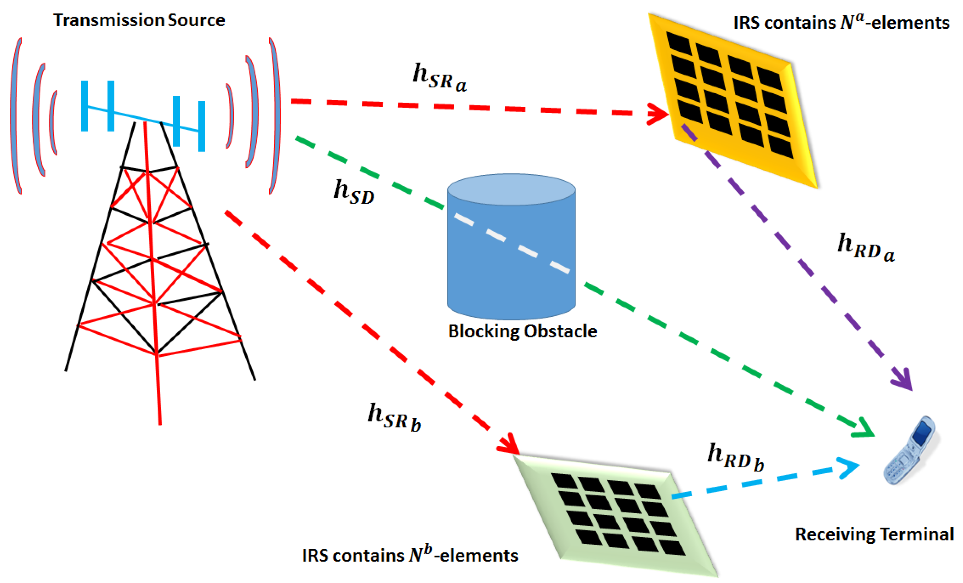
4. The Proposed Multi-IRS Approach

This scenario proposes the case where more than one reflective plane exists in the communication environment. This is mainly to boost the received signal strength and to increase the chances of successful reception, especially on occasions where there is no direct link existing between the source and the destination. Having multiple IRSs would generate a coupling effect upon each other. In this situation, the effect of coupling among those IRSs is modeled using a factor ϱ , which takes a value range of [0, 1]. For IRS-NOMA, since the resources are shared among the serving BSs, this factor value is always 1; hence, it will be omitted from the related expressions.
For simplicity, the considered scenario will include only two IRSs, indexed with a and b, respectively. At the destination, the receiving device receives reflected signals from N b -reflective surfaces, in addition to the direct signal from the source, as clarified in Figure 2. This is to emulate the real-time case where the receiving device could be moving and transferring from the coverage area near one reflective surface into another with a different reflection surface installed, as illustrated in Figure 2. The received signal by the destination could be expressed as
y u = h S D u + h S R a u T Θ h R D a u + h S R b u T Θ h R D b u P I R S N O M A u x u + n u ,
the subscripts a and b refer to the IRS indices, while the rest of the variables have the same definitions as in (1).
Following the concept of a multi-IRS scenario, the expression in (6) would be
P I R S N O M A u N a , N b = 2 S E I R S N O M A u 1 z u + v = u + 1 U P I R S N O M A v Γ S D u + N a α Γ I R S u , a + N b α Γ I R S u , b 2 Γ S D u + N a α Γ I R S u , a + N b α Γ I R S u , b 2
the upper script a , which denotes the parameters associated with the first IRS and b , is associated with the second IRS parameters. For instance, N a and N b refer to the number of reflective elements of the first and second IRS, respectively.

5. Simulation and Numerical Results

The simulations are applied in two different phases. The first one compares the performance of IRS-OMA against IRS-NOMA in terms of several performance metrics under a single IRS-assisted setup. The second phase of the simulation addresses the impact of having more than one IRS. The distance separating the source and the destination d S D is set to vary from 100 m to 150 m. It is also assumed that the distance between the source and the IRS plane d S R is set as 100 m, while the minimum distance between destination and the IRS plane d R D is chosen to be 5 m. The power amplifier efficiency η P A is chosen as 0.38. The simulated channel is chosen in accordance with 3GPP standards with deterministic characteristics as a function of the distance, as listed in Table 1.

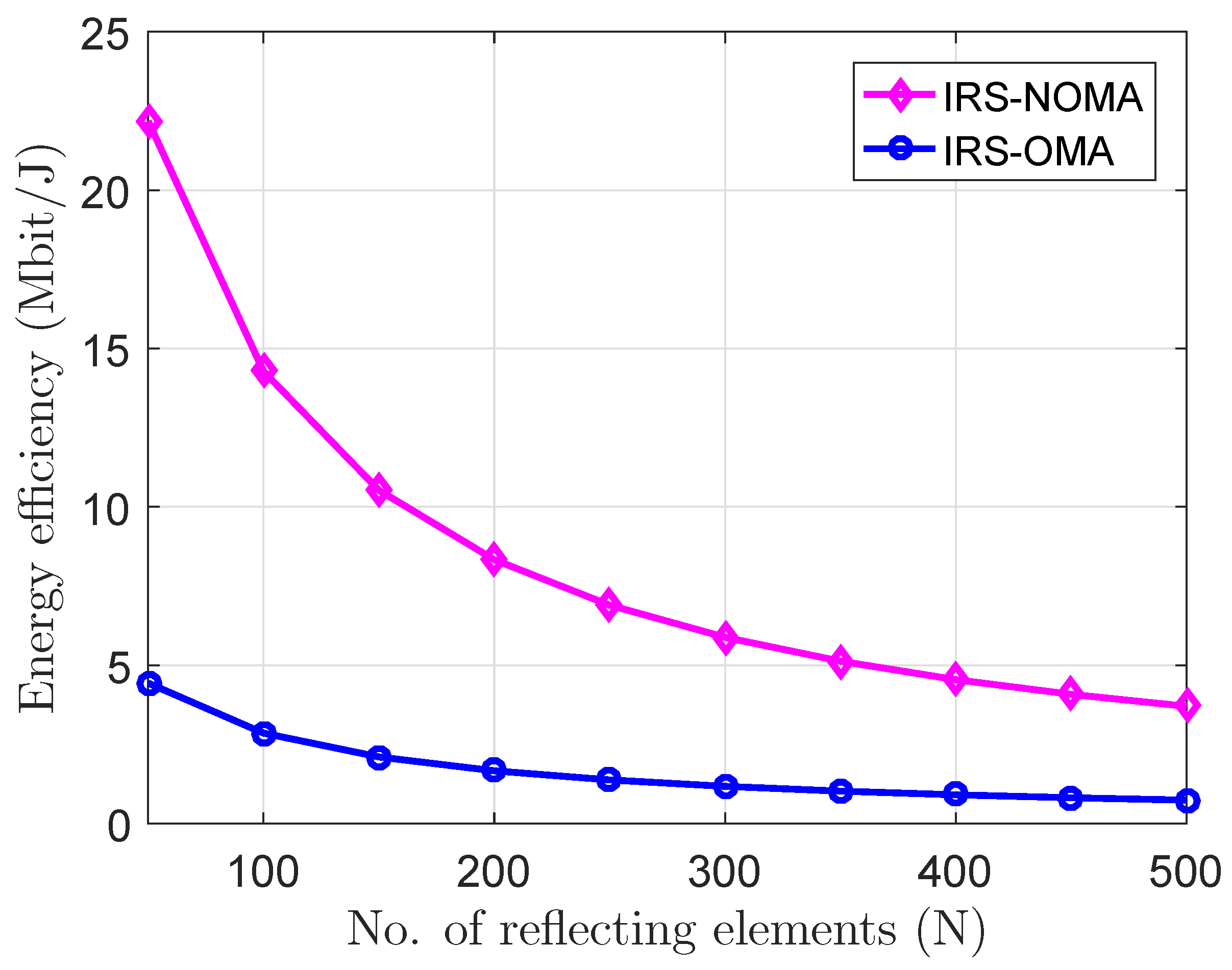
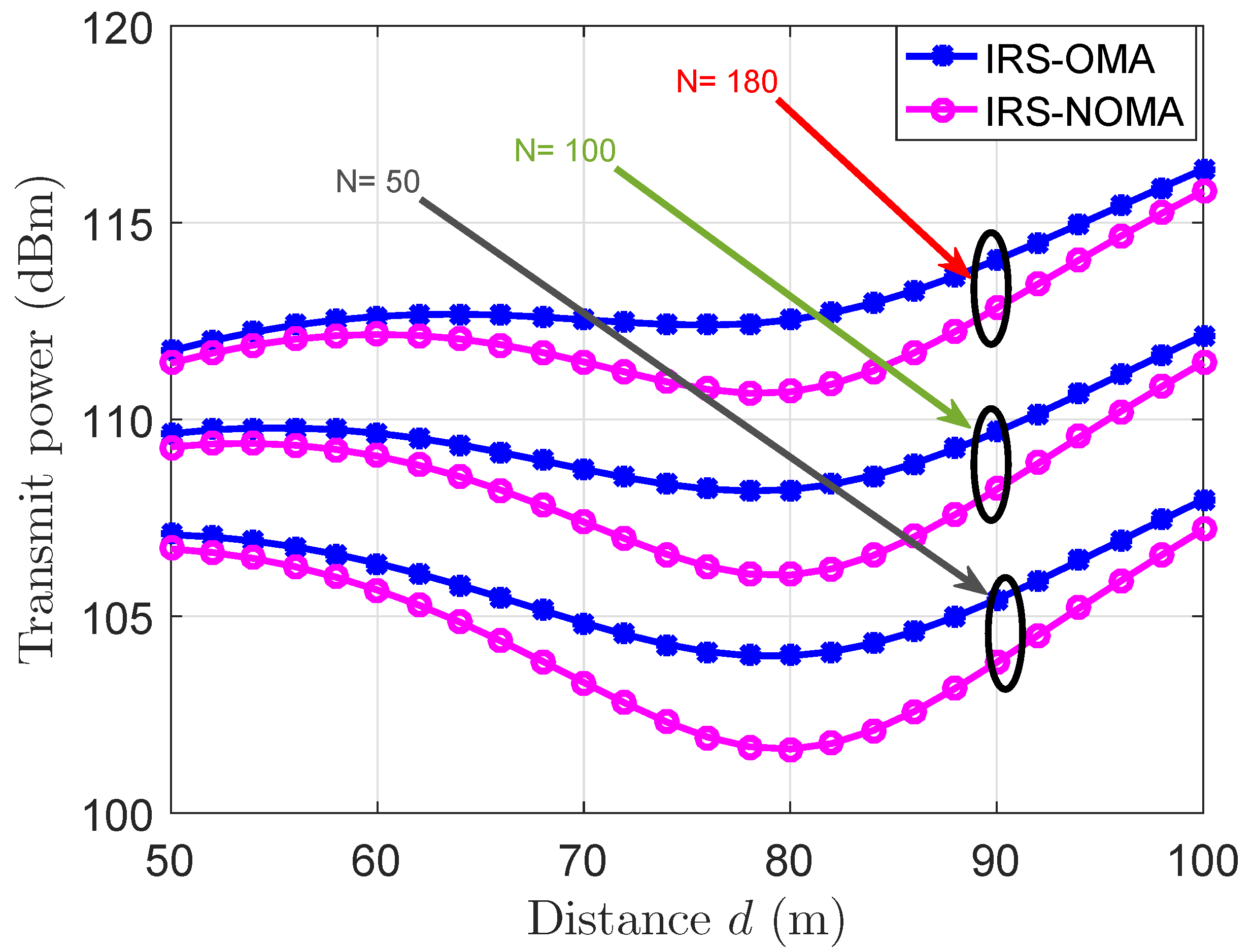
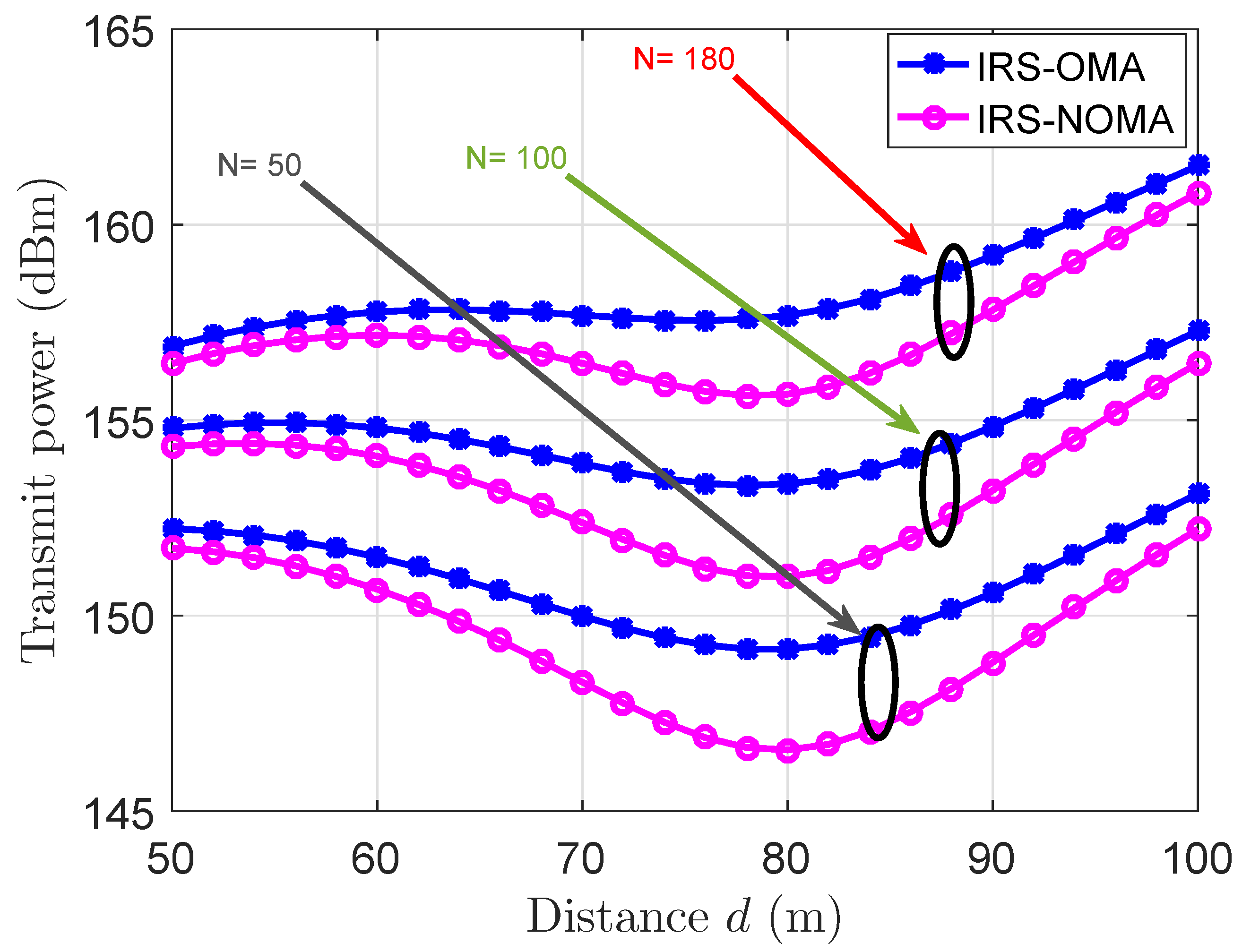
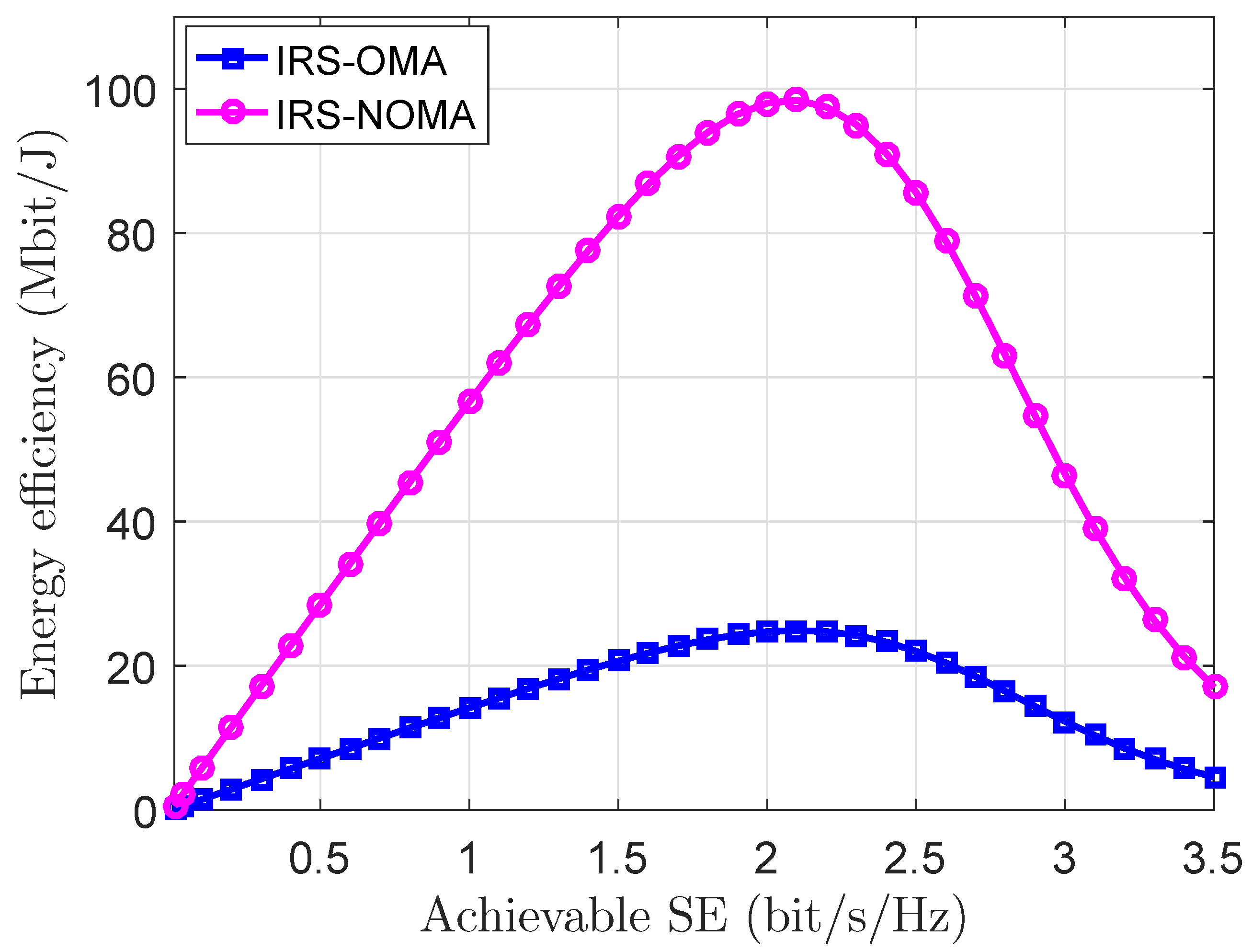
5.1. Numerical Results of a Single-Reflection Surface Scenario

Figure 3 illustrates a comparison between IRS-NOMA and IRS-OMA in terms of the required number of reflective elements N against the achievable EE, with both system being required to maintain a specified level of the target rate. It is worth mentioning that the expression of EE is
E E = B S E P T o t c o n s .
The performance is examined at high N values to surveillance the behaviors of both systems in such a situation. This figure depicts that IRS-NOMA achieves the same EE as IRS-OMA, but with much less reflective elements; for instance, it could be observed that at N = 300 , IRS-NOMA achieves approximately double EE than that achieved by IRS-OMA. This proves that IRS-NOMA is less complex and more cost effective than IRS-OMA, and this figure shows that IRS-NOMA outperforms IRS-OMA at high levels of N.
Despite the fact that IRS-NOMA offers better outcomes than IRS-OMA, Figure 3 shows that EE trends in general are declining for both systems, which reflects the fact that higher N levels lead to more power consumption and more non-useful wave scattering, which causes power wastage, and therefore is non-energy efficient. It is worth mentioning that, from Figure 3, the EE decreases continuously as N increases; however, this merely extends to a certain level, and then EE starts to reach a steady state where increasing N is not effective.
To test the IRS-NOMA and IRS-OMA abilities to achieve given target rates, Figure 4 and Figure 5, respectively, show the required transmission power by both systems to reach a predetermined target rate, and at the same time, maintain successful transmission over a given distance between the source and the destination. To examine the effects of all the respective variables, the two figures considered three different N scenarios: 50, 100, and 180, besides varying the target rate between 50 Mbit/s and 100 Mbit/s, over several d measurements. It is worth mentioning that the achievable target rate for the users of both systems is affected by several factors such as the available transmission power allocated to each user and the channel conditions of each user. Increasing the distance or placing the destinations at farther locations will degrade the performance to a point where the users with bad channel conditions will need more transmission power to achieve a given target rate. It can be concluded from both of these figures that IRS-NOMA requires less power than its orthogonal peer. This proves and confirms that IRS-NOMA requires less transmission power, and hence, is more energy efficient than IRS-OMA for various destination locations.
Figure 6 displays the EE-SE trade-off for IRS-NOMA against IRS-OMA. This figure shows that the EE-SE relationship is a convex function of SE, and it also illustrates that IRS-NOMA considerably outperforms IRS-OMA in terms of the achievable EE for different SE levels.

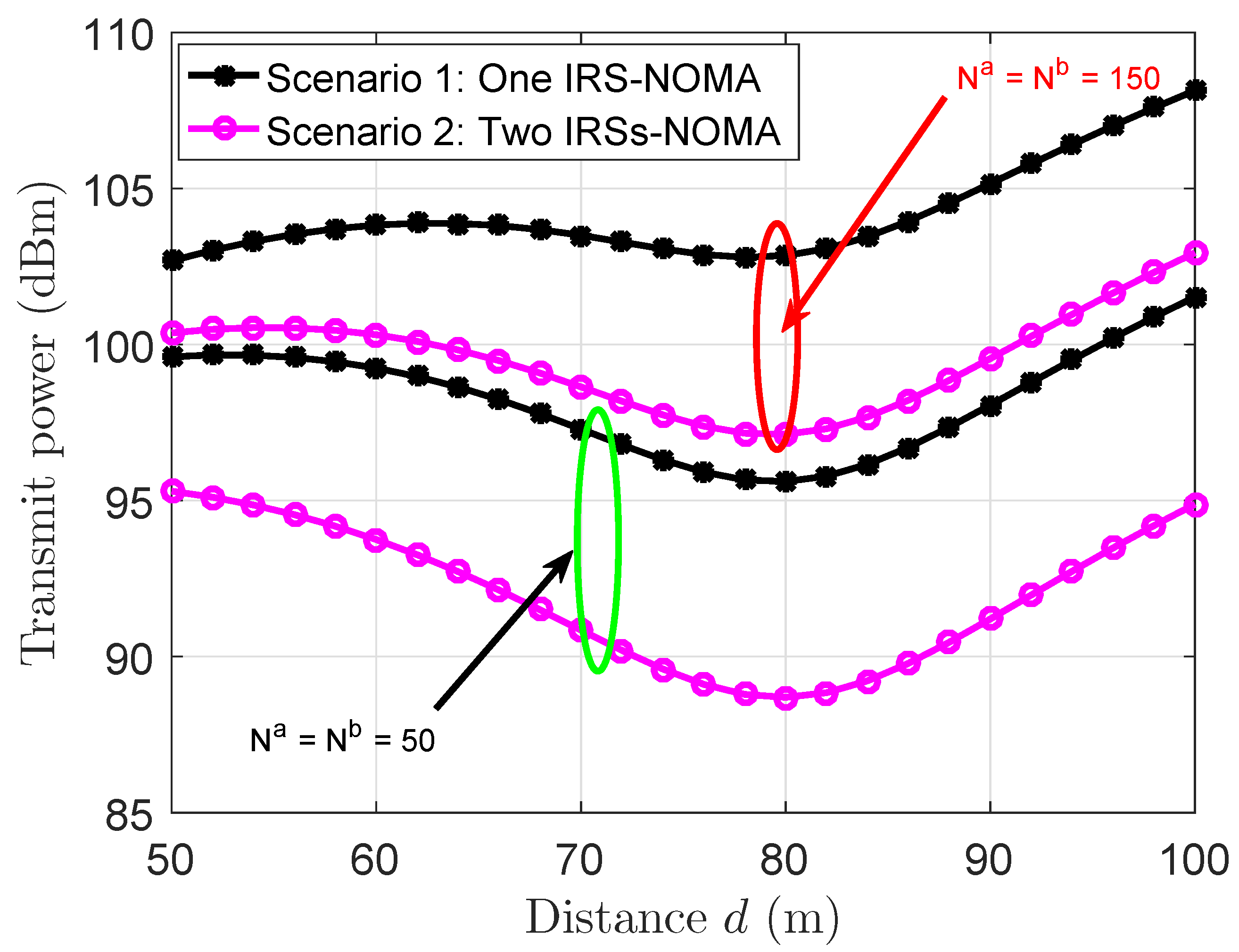
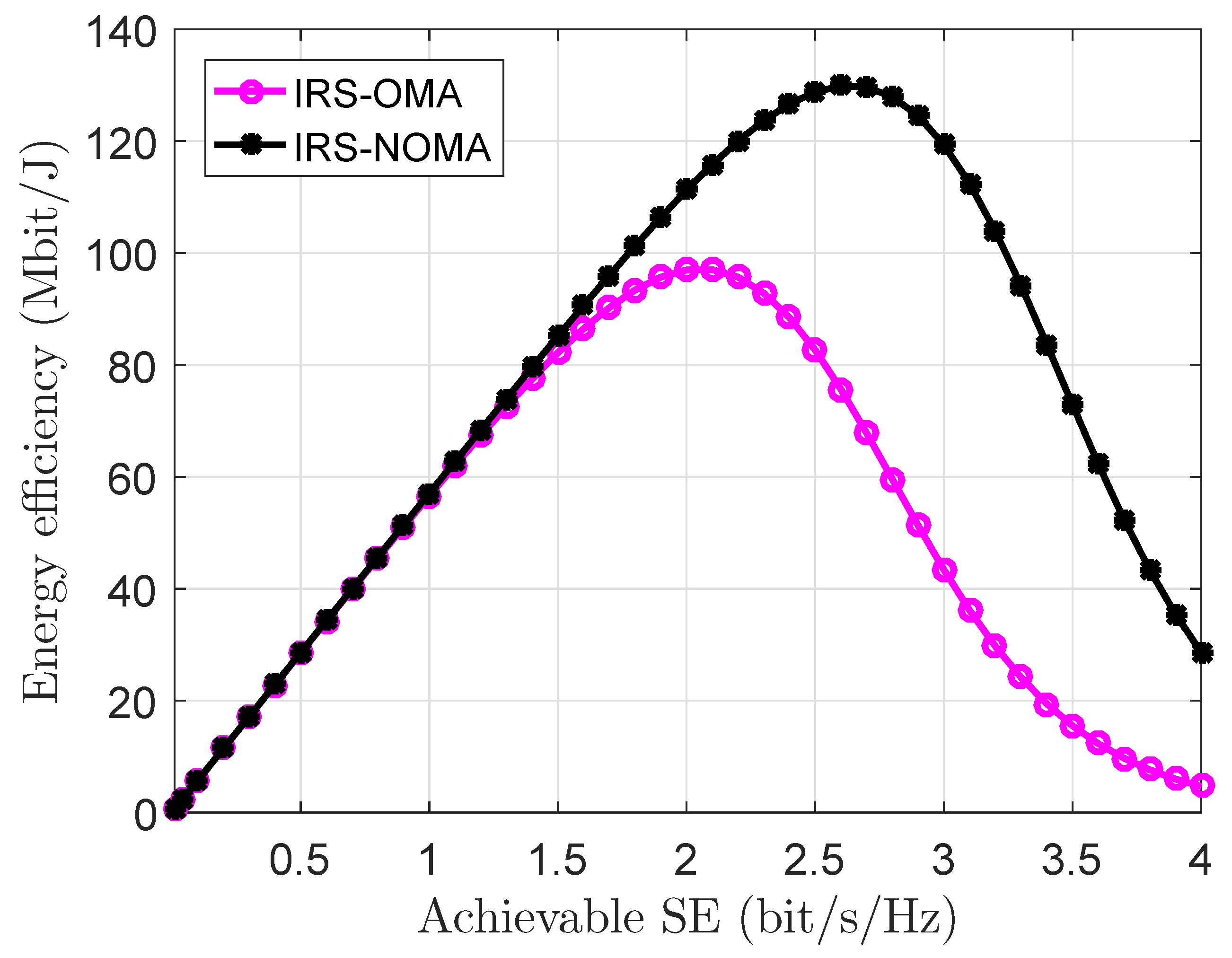
5.2. Numerical Results of a Two-Reflection-Surfaces-Assisted NOMA Scenario

The numerical results obtained in the previous scenario already proved that IRS-NOMA is superior to IRS-OMA. Therefore, this section will consider the performance of IRS-NOMA only, but under the proposed multi-IRS-assisted NOMA scenario. The distances in the two-IRSs-based setup are chosen where d S R a is 100 m, while d S R b is set as 120 m; on the other hand, d R D a and d R D b were chosen to be 10 m and 5 m, respectively. It is worth mentioning that d S D is kept the same and it ranges between 100 m to 150 m.
Figure 7 displays a comparison between the proposed two-IRS-assisted NOMA system against the conventional IRS-NOMA system. The comparison is made in terms of the required transmission power over the distance to achieve a target rate of 100 Mbit/s and for N = 50 and N = 150 cases. It is obvious from this figure that the proposed two-IRS-assisted NOMA offers better results than the conventional IRS-NOMA. For instance, for the N a = N b = N = 150 case, at a distance of 80 m, the proposed two-IRS NOMA requires a transmission power at around 98 dBm, while the conventional IRS-NOMA requires about 103 dBm. It must be noted that it is possible to achieve a higher target rate when the channel power (channel conditions) is good; however, the users with poor channel conditions might face a considerable challenge to maintain a higher target rate without adopting a higher transmission power.
Figure 8 below compares the behaviors of IRS-NOMA systems through the one-IRS and the proposed two-IRS-assisted NOMA scenarios. The trends clarify that the proposed two-IRS case offers a better EE-SE trade-off than the one IRS case. This is because the extra IRS plane will boost the received signal and improve the reception experience, and this will lead to a better achievable SE, and hence, to a better EE.

6. Conclusions and Future Directions

This paper presented solutions to improve the performance of the IRS-based NOMA system. An optimized approach is obtained to find the optimal number of reflective elements in the IRS-NOMA system. In addition, a new multi-IRS approach is proposed to further improve its performance. Simulation results show that the combination of IRS and NOMA offers very promising performance trends in terms of EE and SE, as well as the trade-off between them. In addition, adopting the idea of multiple IRSs proved its effectiveness in boosting the user’s experience, and in improving the propagation environment. Utilizing multiple IRSs could also act as a cost-effective solution, as it reduces the required number of serving BSs in a given geographical coverage area. In future works, it is necessary to consider the case where the IRS plane is not at a fixed place, but rather, it could be moving in favor of a better reception experience. It is also interesting to examine the combination of IRS and techniques such as cognitive IRS, massive-MIMO (mMIMO), and cell-free massive MIMO system, especially in terms of the SE gains that these combinations could offer.

Author Contributions

Methodology, Z.Q.A.-A., L.F. and R.S.A.; Software, Z.Q.A.-A., L.F. and R.S.A.; Formal analysis, R.S.A.; Investigation, Z.Q.A.-A., L.F. and R.S.A.; Resources, Z.Q.A.-A. and R.S.A.; Data curation, L.F.; Writing—original draft, Z.Q.A.-A. and L.F.; Writing—review & editing, R.S.A. All authors have read and agreed to the published version of the manuscript.

Funding

This research received no external funding.

Data Availability Statement

Not applicable.

Conflicts of Interest

The authors declare no conflict of interest.

References

  1. Al-Abbasi, Z.Q.; So, D.K.C.; Tang, J. Energy Efficient Resource Allocation in Downlink Non-Orthogonal Multiple Access (NOMA) System. In Proceedings of the 2017 IEEE 85th Vehicular Technology Conference (VTC Spring), Sydney, Australia, 4–7 June 2017; pp. 1–5. [Google Scholar]
  2. Al-Abbasi, Z.Q.; So, D.K.C. Resource Allocation in Non-Orthogonal and Hybrid Multiple Access System with Proportional Rate Constraint. IEEE Trans. Wirel. Commun. 2017, 16, 6309–6320. [Google Scholar] [CrossRef] [Green Version]
  3. Luo, F.L.; Zhang, C. Signal Processing for 5G: Algorithms and Implementations; John Wiley & Sons: Hoboken, NJ, USA, 2016. [Google Scholar]
  4. Dai, Y.; Sheng, M.; Liu, J.; Cheng, N.; Shen, X.; Yang, Q. Joint Mode Selection and Resource Allocation for D2D-Enabled NOMA Cellular Networks. IEEE Trans. Veh. Technol. 2019, 68, 6721–6733. [Google Scholar] [CrossRef]
  5. Men, J.; Ge, J. Non-Orthogonal Multiple Access for Multiple-Antenna Relaying Networks. IEEE Commun. Lett. 2015, 19, 1686–1689. [Google Scholar] [CrossRef]
  6. Al-Abbasi, Z.Q.; So, D.K.C.; Tang, J. Resource allocation for MU-MIMO non-orthogonal multiple access (NOMA) system with interference alignment. In Proceedings of the 2017 IEEE International Conference on Communications (ICC), Paris, France, 21–25 May 2017. [Google Scholar] [CrossRef] [Green Version]
  7. Al-Abbasi, Z.Q.; Rabie, K.M.; So, D.K.C. EE Optimization for Downlink NOMA-Based Multi-Tier CRANs. IEEE Trans. Veh. Technol. 2021, 70, 5880–5891. [Google Scholar] [CrossRef]
  8. Liu, Y.; Pan, G.; Zhang, H.; Song, M. On the Capacity Comparison Between MIMO-NOMA and MIMO-OMA. IEEE Access 2016, 4, 2123–2129. [Google Scholar] [CrossRef]
  9. Martin-Vega, F.J.; Liu, Y.; Gomez, G.; Aguayo-Torres, M.C.; Elkashlan, M. Modeling and Analysis of NOMA Enabled CRAN with Cluster Point Process. In Proceedings of the GLOBECOM 2017—2017 IEEE Global Communications Conference, Singapore, 4–8 December 2017; pp. 1–6. [Google Scholar] [CrossRef]
  10. Dani, M.N.; Al-Abbasi, Z.Q.; So, D.K.C. Power Allocation for Layered Multicast Video Streaming in Non-Orthogonal Multiple Access System. In Proceedings of the 2017 IEEE Globecom Workshops (GC Wkshps), Singapore, 4–8 December 2017; pp. 1–6. [Google Scholar] [CrossRef] [Green Version]
  11. De Sena, A.S.; Carrillo, D.; Fang, F.; Nardelli, P.H.; Da Costa, D.B.; Dias, U.S.; Ding, Z.; Papadias, C.B.; Saad, W. What role do intelligent reflecting surfaces play in multi-antenna non-orthogonal multiple access? IEEE Wirel. Commun. 2020, 27, 24–31. [Google Scholar] [CrossRef]
  12. Al-Abbasi, Z.Q.; Khamis, M.A. Spectral efficiency (SE) enhancement of NOMA system through iterative power assignment. Wirel. Netw. 2021, 279, 1309–1317. [Google Scholar] [CrossRef]
  13. Sun, Q.; Han, S.; I, C.L.; Pan, Z. On the Ergodic Capacity of MIMO NOMA Systems. IEEE Wirel. Commun. Lett. 2015, 4, 405–408. [Google Scholar] [CrossRef]
  14. Sun, Q.; Han, S.; I, C.L.; Pan, Z. Energy efficiency optimization for fading MIMO non-orthogonal multiple access systems. In Proceedings of the 2015 IEEE International Conference on Communications (ICC), London, UK, 8–12 June 2015; pp. 2668–2673. [Google Scholar] [CrossRef]
  15. Li, Q.; Ren, P.; Xu, D. Security Enhancement and QoS Provisioning for NOMA-Based Cooperative D2D Networks. IEEE Access 2019, 7, 129387–129401. [Google Scholar] [CrossRef]
  16. Chen, J.; Jia, J.; Liu, Y.; Wang, X.; Aghvami, A.H. Optimal Resource Block Assignment and Power Allocation for D2D-Enabled NOMA Communication. IEEE Access 2019, 7, 90023–90035. [Google Scholar] [CrossRef]
  17. Fu, M.; Zhou, Y.; Shi, Y. Intelligent reflecting surface for downlink non-orthogonal multiple access networks. In Proceedings of the 2019 IEEE Globecom Workshops (GC Wkshps), Waikoloa, HI, USA, 9–13 December 2019; pp. 1–6. [Google Scholar]
  18. Al Abbasi, Z.Q.; Ahmed Khamis, M.; Rabie, K.M. Performance Evaluation of Downlink IRS-Assisted Multi-Cell Massive MIMO System. In Proceedings of the 2021 IEEE International Mediterranean Conference on Communications and Networking (MeditCom), Athens, Greece, 7–10 September 2021; pp. 138–143. [Google Scholar] [CrossRef]
  19. Özdogan, Ö.; Björnson, E.; Larsson, E.G. Intelligent reflecting surfaces: Physics, propagation, and pathloss modeling. IEEE Wirel. Commun. Lett. 2019, 9, 581–585. [Google Scholar] [CrossRef] [Green Version]
  20. Dampahalage, D.; Shashika Manosha, K.B.; Rajatheva, N.; Latva-aho, M. Intelligent Reflecting Surface Aided Vehicular Communications. In Proceedings of the 2020 IEEE Globecom Workshops (GC Wkshps), Taipei, Taiwan, 7–11 December 2020; pp. 1–6. [Google Scholar] [CrossRef]
  21. Björnson, E.; Özdogan, Ö.; Larsson, E.G. Intelligent reflecting surface versus decode-and-forward: How large surfaces are needed to beat relaying? IEEE Wirel. Commun. Lett. 2019, 9, 244–248. [Google Scholar] [CrossRef] [Green Version]
  22. Mu, X.; Liu, Y.; Guo, L.; Lin, J.; Al-Dhahir, N. Exploiting intelligent reflecting surfaces in NOMA networks: Joint beamforming optimization. IEEE Trans. Wirel. Commun. 2020, 19, 6884–6898. [Google Scholar] [CrossRef]
  23. Ding, Z.; Poor, H.V. A simple design of IRS-NOMA transmission. IEEE Commun. Lett. 2020, 24, 1119–1123. [Google Scholar] [CrossRef]
  24. Ding, Z.; Schober, R.; Poor, H.V. On the impact of phase shifting designs on IRS-NOMA. IEEE Wirel. Commun. Lett. 2020, 9, 1596–1600. [Google Scholar] [CrossRef]
  25. Tekbıyık, K.; Kurt, G.K.; Yanikomeroglu, H. Energy-Efficient RIS-assisted Satellites for IoT Networks. arXiv 2021, arXiv:2101.07166. [Google Scholar] [CrossRef]
  26. Lin, Z.; An, K.; Niu, H.; Hu, Y.; Chatzinotas, S.; Zheng, G.; Wang, J. SLNR-based Secure Energy Efficient Beamforming in Multibeam Satellite Systems. IEEE Trans. Aerosp. Electron. Syst. 2022, 1–14. [Google Scholar] [CrossRef]
  27. Lin, Z.; Niu, H.; An, K.; Wang, Y.; Zheng, G.; Chatzinotas, S.; Hu, Y. Refracting RIS-Aided Hybrid Satellite-Terrestrial Relay Networks: Joint Beamforming Design and Optimization. IEEE Trans. Aerosp. Electron. Syst. 2022, 58, 3717–3724. [Google Scholar] [CrossRef]
  28. Lin, Z.; Lin, M.; Wang, J.B.; de Cola, T.; Wang, J. Joint Beamforming and Power Allocation for Satellite-Terrestrial Integrated Networks With Non-Orthogonal Multiple Access. IEEE J. Sel. Top. Signal Process. 2019, 13, 657–670. [Google Scholar] [CrossRef]
Figure 1. An illustration of the modeled IRS-assisted system.
Electronics 11 04045 g001
Figure 2. The proposed two IRS-assisted scenarios.
Electronics 11 04045 g002
Figure 3. EE trends against various numbers of reflective elements.
Electronics 11 04045 g003
Figure 4. The required transmission power by IRS-NOMA and IRS-OMA for different destination locations to achieve a target rate of 50 Mbit/s.
Electronics 11 04045 g004
Figure 5. The required transmission power by IRS-NOMA and IRS-OMA for different destination locations to achieve a target rate of 100 Mbit/s.
Electronics 11 04045 g005
Figure 6. EE-SE trade-off of both IRS-NOMA against IRS-OMA.
Electronics 11 04045 g006
Figure 7. The required transmission power versus the achievable SE for IRS-NOMA.
Electronics 11 04045 g007
Figure 8. EE-SE trade-off of IRS-NOMA in two scenarios.
Electronics 11 04045 g008
Table 1. Simulation Setup.
Parameter NameValue
Total number of active users U 3
Carrier frequency f c 5 GHz
Overall transmission bandwidth B 10 MHz
The standard deviation of shadowing8 dB
the total transmission power P 40 dBm
Dissipated power by each reflective element P E 5 mW
Dissipated power by the source P S 20 dBm
Dissipated power by the destination P D 100 mW
Dissipated power by the rely P R 100 mW
Noise power spectral density σ 2 −174 dBm/Hz
β S R = 28 20 l o g 10 ( f c ) 22 l o g 10 ( d S R ) + G S + G R 3GPP LOS path-loss
β R D = 28 20 l o g 10 ( f c ) 22 l o g 10 ( d R D ) + G R + G D 3GPP LOS path-loss
β S D = 22.7 26 l o g 10 ( f c ) 36.7 * l o g 10 ( d S D ) + G S + G D 3GPP NLOS path-loss
Noise figure10 dB
The reflection coefficient α 1
Transmitting antenna gain G S 5 dB
Receiving antenna gain G R 5 dB
Transmitting antenna gain G D 1 dB
Publisher’s Note: MDPI stays neutral with regard to jurisdictional claims in published maps and institutional affiliations.

