Article

A PSO-Based Approach for Optimal Allocation and Sizing of Resistive-Type SFCLs to Enhance the Transient Stability of Power Systems

1
Department of Engineering, University of Zanjan, Zanjan 45371-38791, Iran
2
Department of Electrical and Computer Engineering, Sungkyunkwan University, Suwon 16419, Republic of Korea
*
Author to whom correspondence should be addressed.
Electronics 2022, 11(23), 3980; https://doi.org/10.3390/electronics11233980
Submission received: 25 October 2022 / Revised: 26 November 2022 / Accepted: 29 November 2022 / Published: 30 November 2022
(This article belongs to the Special Issue Voltage Control and Protection in Power Systems)

Abstract

:
Transient stability improvement of power systems in the event of short-circuit faults has always been an important issue in power systems analysis and studies. Resistive-type superconducting fault current limiters (RSFCL), owing to their capability in restricting fault currents, have been often taken into account as an efficient method to improve the transient stability of a power system. Regarding technical constraints as well as economic concerns, optimal allocation and sizing of RSFCLs in a power system play a crucial role in their efficient utilization. This paper aims to continue the authors’ previous work and enhance the transient stability of power systems by proposing an optimization approach for optimal sizing and the allocation of various candidate numbers of RSFCLs, as the most employed type of SFCL and the most efficient one in transient stability improvement. To solve the optimization problem, a PSO-based algorithm is solved in MATLAB through an objective function and related constraints. The efficacy of the proposed algorithm is evaluated by numerical studies on the IEEE 39-Bus New England system in various scenarios through the assessment of critical fault clearing time (CCT) as well as the generators rotor angle deviations as two crucial criteria for the transient stability of power systems. Simulating the optimization results in DIgSILENT Power Factory indicates an evident enhancement of the power system transient stability via employing optimized RSFCLs resulted from the proposed optimization algorithm. Moreover, the level of transient stability enhancement highly depends on the number of optimized RSFCLs employed in the power system. The results of this paper present a helpful guideline for power system planners to select an appropriate stability scheme based on RSFCLs besides other related technical and economic issues.

1. Introduction

Electric power systems are always susceptible to large disturbances such as short-circuit faults as the most common failures [1,2]. In the event of short-circuit faults, the fault is to be cleared as soon as possible and the fault current must be limited; otherwise, it may result in severe problems, including stability problems, especially transient stability risks. Superconducting fault current limiters (SFCL) are one of the leading topics of current-limiting technologies in the world [3]. In addition to economic benefits, limiting the short-circuit current using SFCLs has many technical advantages, including almost no power losses or voltage drops during normal operation, no considerable overvoltage or harmonic injection in steady-state conditions, voltage stability improvement by preventing fast voltage drop, reduction of instant large reactive power demanded by reactive impedances during a short-circuit fault, and the most crucial one, the transient stability enhancement of the power system [4,5,6]. Among various types of SFCLs, resistive-type SFCLs have been the most employed SFCL so far [3]. This is due to their simple structure, small size, low weight, and needing less superconductive material, which significantly reduces the related costs compared to other types of SFCLs [3,4]. As mentioned above, employing SFCLs can be considered one of the beneficial methods to improve the transient stability of a power system. However, regarding technical constraints as well as economic concerns, their optimal sizing and allocation in a power system will be of great importance [7,8]. The effect of SFCLs on power systems’ transient stability has been studied so far in several papers. The effectiveness of resistive-type superconducting fault current limiters RSFCLs with optimal shunt resistors in the transient stability improvement of a power system has been admitted in [9] based on the minimization of rotor kinetic energy oscillations and simulations by EMTP/ATP. The improvement of transient behaviors in ring networks has been analyzed in [10] by employing optimal SFCLs using a micro-genetic algorithm (micro-GA) combined with a hierarchical genetic algorithm (HGA) to simultaneously search for the optimal location and SFCL capacity. The efficacy of the proposed approach is revealed by numerical studies with a loop power system. Utilizing a series of proposed RSFCLs to enhance the transient stability of power systems has been modeled and simulated in [11]. The result of this work demonstrates the efficiency of the optimal value of RSFCLs in the stability enhancement, as well as damping improvement of rotor angle oscillations in power systems. In [12], the effect of SFCLs on the dynamic behavior of generators in the event of a three-phase short circuit in a two-machine-infinite bus system has been simulated and analyzed using EMTP/ATP, demonstrating the efficient role of SFCLs in the transient stability improvement of power systems. It is concluded that employing SFCL with shunt resistance is effective for all fault points for enhancing the transient stability and limiting the fault current. Employing RSFCL as a powerful controller to improve the transient stability of power systems has been simulated in [13], and a method to assess an appropriate resistance is proposed, the result of which is that the higher the value of the resistance, the more the improvement in transient stability. Enhancement of transient stability in a large number of low-voltage-connected induction micro-generators using RSFCLs has been assessed in [14], revealing the efficiency of RSFCLs in preventing the micro-generators from reaching their speed limits during remote faults and hence, improving their transient stability. In addition, the minimum value of a resistive element of RSFCL required for improving the transient instability of LV-connected micro generation based on the system and connected machine parameters has been calculated. Power systems’ transient stability enhancement in a multi-machine power system by the combined operation of SFCL and optimal reclosing of circuit breakers has been executed in [15], wherein the total kinetic energy (TKE) of the generators has been employed in order to investigate the transient stability improvement. Simulation results specify the good enhancement of the transient stability by employing the proposed combination of the optimal reclosing of circuit breakers and SFCLs. Robust control of combined genetic-algorithm-based optimization of RSFCL and energy capacitor storage (ECS) has been utilized in [16] for power system transient stability enhancement. Simulation results of this paper show that the combination of suitable RSFCL and ECS can improve the transient stability of power systems better than employing stand-alone ECS. Transient stability improvement in microgrids using RSFCL with a series active power filter has been studied in [17], concluding that RSFCL with series-active power filters compensates for the voltage magnitudes and reduces the harmonics and therefore, results in the improvement of the transient stability. In [18], employing a method based on the equal area criterion, selecting the location of RSFCL and inductive-type SFCL (ISFCL) was investigated, taking into account the transient stability issue, and it was concluded that RSFCL is a better choice than ISFCL for improving transient stability power systems. A comparison between resistive and inductive types of SFCL considering the current limitation and transient stability of power systems has been studied in [19] using a method based on the equal area criterion to assess the critical clearing angle (CCA) as well as a time-domain approach to investigate the critical clearing time (CCT) for transient stability analysis. The results of this paper demonstrate that the RSFCL is better at limiting the fault current and hence, improving the power system transient stability in the event of a short circuit. Finally, a new approach has been proposed in [20] for the optimal allocation of RSFCLs to improve the transient stability of a power system using the sensitivity analysis of the angular deviation of synchronous generators. It has been revealed that RSFCL may have positive and negative impacts according to its location in the event of a fault occurrence. Moreover, the transient stability improvement of the power system is related to the optimal location and value of the RSFCLs in a way that their optimal locations and values decrease the rotor angular deviations, resulting in the efficient enhancement of the transient stability.
Reviewing the above-mentioned literature and to the best of the authors’ knowledge, it can be concluded that, although the role of resistive-type SFCLs in the transient stability improvement of power systems and their comparison with other types of SFCLs or other means of transient stability enhancements have been studied in various papers, few researchers have so far taken into account the optimal sizing and allocation of RSFCLs for the purpose of the transient stability enhancement of power systems. Therefore, regarding the fact that the number and values of RSFCLs in power systems are restricted due to economic issues as well as technical constraints, their optimal allocation and sizing can result in their feasible employment in power systems. The authors of this paper have previously performed a study [21], wherein the sizes and locations of a specified number of resistive-type SFCLS are optimized based on a selected short-circuit fault for the objective of transient stability enhancement. Furthermore, in our previous work, the optimization is performed for a fixed number of five RSFCLs and the criterion of the transient stability assessment is limited only to the generators’ rotor angle deviations, and no CCT evaluations have been done. In this paper, we aim to continue and complete our previous work through a detailed optimization of various candidate numbers of RSFCLs in order to improve the transient stability for a carefully selected short-circuit fault. In addition, comprehensive CCT investigation is performed in our new work to compare the effect of different numbers of optimized RSFCLs on the transient stability enhancement. We propose an algorithm based on particle swarm optimization in order to improve the transient stability of power systems by the optimal sizing and allocation of RSFCLs, as the most employed type of SFCL regarding their above-mentioned advantages. To solve the optimization problem, a meta-heuristic approach is proposed and solved by a PSO-based algorithm in MATLAB using Power System Toolbox for transient stability analysis [22]. Optimization results are simulated by means of DIgSILENT Power Factory [23], a powerful package with detailed models of power system elements as well as accurate calculation methods.
The main contributions of this paper are summarized as follows:
(1)
The optimization problem is solved for two cases, considering three and five RSFCLs due to a trade-off between technical and economic issues. Results are compared based on a detailed analysis.
(2)
Two main criteria are considered for the assessment of transient stability enhancement including the critical fault clearing time (CCT) as well as the generators’ maximum rotor angle deviations. Comprehensive simulations and investigations are performed for both criteria.
(3)
The three-phase short-circuit fault location is carefully selected regarding the maximum normal condition power flow of the selected transmission line, which will result in a larger power swing in the event of its short-circuit fault occurrence, leading to more serious transient instability issues.
The remainder of this paper is as follows: Resistive superconductive fault current limiters are briefly reviewed in Section 2. The proposed optimization problem is formulated in Section 3, and the solution PSO-based algorithm, along with a review of particle swarm optimization, is presented in Section 4. Numerical studies are conducted in Section 5, and simulation results are discussed in Section 6. Finally, conclusions and suggestions for future work are presented in Section 7.

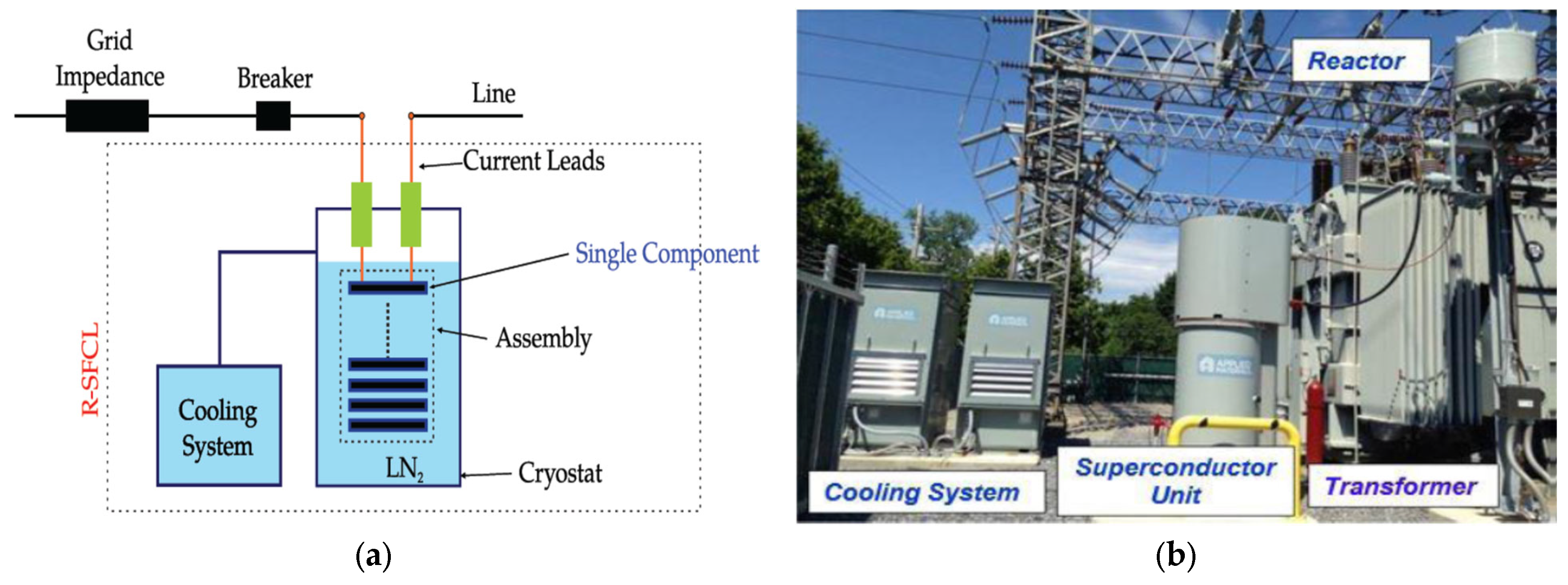
2. Resistive Superconducting Fault Current Limiters

The SFCL principle is based on high-temperature superconductor (HTS) materials [3]. The HTS material makes it possible to have a quickly increased resistance and be variable from a superconducting state to a normally conducting state [4]. In normal operations, the SFCL is in superconducting mode and has almost no electrical resistance and no losses under a certain current density, temperature, or magnetic field [3]. However, over a certain temperature, it will be in current-limiting mode, injecting high impedance into the fault path to limit the fault current. Thus, SFCLs are connected in series with the power system and their impedance is varied regarding the operating condition [3]. In the event of faults and due to a temperature rise, current density, or magnetic field, the variable impedance of the SFCL is increased to a value that can limit the fault current. The discovery of HTS has considerably improved the economic operation of SFCLs regarding the capability of HTS materials for operation at higher temperatures [24]. SFCLs employ a quench characteristic for limiting the fault current, and they must recover their initial condition after fault clearance [25,26]. The thermal energy stored inside the superconductor results in quenching, and, once the fault current is limited, it resets [27,28].
SFCLs consist of various types, including the resistive type, inductive type, and saturated-core type, etc., among which the resistive-type SFCL is the most developable and commercial type due to its simple structure, low weight and small size, and lower required amount of superconductive material, which leads to reduced operation cost [3,27,28]. Indeed, the RSFCL is a nonlinear resistor with no resistance in normal conditions but a high resistance in fault events, which limits the fault current by increasing the current density in the superconductor for a limited time. Its operation is based on the physical properties of its superconductor element and thus, no external controls are required [3]. Figure 1a shows the schematic of a RSFCL in series with a line, and a practical installation of SFCL is presented in Figure 1b. The superconducting element is immersed into a coolant bath as the main current-carrying conductor, which passes the normal load current with theoretically zero losses [29].
Figure 2 illustrates a simple model of RSFCL in a single-machine infinite bus (SMIB) system. A typical RSFCL is usually consisted of n interconnected units in which every unit involves a shunt resistance, RShunt, in parallel with a superconductor resistance of RSC [11,28]. RShunt and RSC are zero in normal steady-state condition. Once the quenching is occurred, they will have non-zero time-varying values [20]. Total resistance of the RSFCL during a fault depends on the series-connected number of units.
Therefore, a RSFCL can be presented by time-varying resistance as follows [11]:
R S F C L   ( t )     =   { 0 , t 0   >   t   R m   [ 1     e (     t     t 0     T S C ) ] 1 2 , t 0     t     <   t 1     a 1   ( t   t 1   )   +   b 1 , t 1     t     <   t 2   a 2     ( t     t 2   )   +   b 2 , t 2     t  
where t0 is the quenching start time, and t1 and t2 are the first and second recovery times, respectively. TSC is typically considered to be 1 m.s. [11].
RSFCLs can be applied in power systems at different voltage levels and in various positions, mainly including generator feeder, transformer feeder, network coupling, outgoing feeder, and bus bar coupling [31,32,33]. Figure 3 shows the possible applications of SFCLs in the power system.

3. Problem Formulation

3.1. Objective Function

Transient stability evaluation in a power system plays a crucial role in view of contingency classification and providing indications for power systems planning and design, and many studies have been performed to improve the methods for the numerical analysis of power system transient stability [34,35,36]. Transient stability is a situation in which the machines remain in synchronism once a severe disturbance occurs in the system. As far as the system is operating in the steady-state condition, there is equilibrium between the mechanical input power of each unit and the electrical power output of that unit, in addition to total losses. However, an unexpected change in the electrical power output caused by a severe and sudden disturbance will obliterate this balance, which will result in accelerating power as follows [37,38]:
P a = P m P e
Hence, the accelerating power of the system in the event of a short-circuit fault depends on the difference between the mechanical power and the electrical power. The P e equation can be expressed as:
P e = | E i | | E j | | Y i j | sin ( δ )
where | E i | and | E j | are the transient internal voltage magnitude of generators at buses i and j, respectively. | Y i j | is the element of the bus admittance matrix ( Y b u s ) representing the connection between buses i and j. Finally, ( δ ) is the difference between the voltage angles of buses i and j  (   δ = δ 1 δ 2 ) . When a RSFCL is added to the connection between two generators, its resistance value will be added to the real part of the related element of the Y b u s matrix of the system. Therefore, in the event of a short circuit and considering the SMIB system in Figure 2, the Y b u s matrix element for a connection with RSFCL can be written as [39]:
Y i j = 1 R R S F C L + R e + j X e
where R R S F C L is the resistance of the RSFCL with a value according to (1), and R e and X e are the resistance and reactance of the transmission line between buses i and j, respectively.
The harshness is measured by the drop of this power to a very low or zero value and a significant sudden acceleration of the machines. This concept is expressed by the swing equation as follows [38]:
2 H ω 0 d 2 δ d t 2 = P a
From (3), the relationship between the rotor angle and the accelerating power will be as follows [38]:
d 2 δ d t 2 =   ω 0 2 H ( P m P e )                                           ( d δ d t ) 2   =   ω 0   ( P m     P e ) H   d δ  
The term ( d δ /   d t ) is the speed deviation and is initially zero, but it will change as a result of a disturbance.
The existence of R R S F C L will cause a change in the related element of the Y b u s matrix, resulting in a variation in the voltage angle differences between the generators, as well as the electrical power ( P e ) of the system. A more detailed model of power systems and their transient stability studies in the presence of RSFCLs was presented in [11,19]. Once a fault occurs, the rotor angle of generators will start to oscillate depending on the fault location and its clearing time. In an n-generator power system, one generator is slack, and the remaining (n − 1) generators are considered non-slack generators. To investigate the transient stability of a system in the case of a short-circuit event, the rotor angle (δ) oscillations of non-slack generators are depicted vs. that of the slack generator, wherein the damping of these oscillations in a suitable time interval will reveal the stability of the system [22,38]. Therefore, the area under the rotor angle curve in a specified time interval can be considered a criterion for transient stability assessment. Figure 4 illustrates the δ oscillation of a generator at a time interval of T. The integration of this curve in a [0 − T] interval will result in its area. Hence, the reduced area of the δ oscillation curve denotes that either the amplitude of oscillations are decreased or the oscillations are damped faster, both revealing the transient stability improvement.
Consequently, in this paper, minimizing the total sum of areas under the rotor angle oscillation curves in a specified time interval by means of optimized sizes and locations of candidate RSFCLs in the presence of related constraints has been considered the objective function of the optimization problem for improving the power system transient stability. Hence, the objective function of the problem can be written as follows:
min         O F = [     j = 1 n 1 0 T | δ j ( t ) |     d ( t ) ]                           ;     j     N n s g     ;       j     G S L                                   S u b j e c t       t o :       D e s i c i o n     var i a b l e s     a s     ( 8 )     a n d                                                                                       C o n s t r a i n   t s   ( 9 )     t o     ( 17 )
where [0 − T] is the integration interval, which is considered the post-fault study time. In addition, δ j ( t ) is the rotor angle oscillation of non-slack generators compared to that of the slack-bus generator. Thus, in a power system with n generators, there will be (n − 1) non-slack generators. Therefore, the summation of rotor angle oscillation areas in the objective function has been defined for (n − 1) generators. The objective function is subject to decision variables, as well as the constraints related to power system analysis. In the following, the decision variables, as well as the constraints of the proposed optimization problem, will be explained.

3.2. Decision Variables

The purpose of the optimization problem is to simultaneously optimize the sizes and locations of the set of candidate RSFCLs (CR). Hence, the decision variables (X) of the proposed optimization problem can be defined as follows:
X =   [ S 1 ,   S 2 ,   ,   S C R R S F C L         s i z e   s ,           L 1 ,   L 2 ,   . ,   L C R R S F C L           l o c a t i o n s ]
where S variables denote the sizes of the candidate number of RSFCLs to be optimized, and L variables present their locations. Size variables are per unit (p.u.) of the system base MVA and have continuous values, with upper and lower bounds assigned according to the power system under study. Location variables have discrete values presenting the branch in which the candidate RSFCLs will be located. Consequently, the optimization problem proposed in this paper is a mixed-integer non-linear (MINLP) problem due to the non-linear equations of the power system transient stability evaluation, as well as the AC load flow equations of the power system, which requires an appropriate solution algorithm. In this paper, a meta-heuristic algorithm based on the particle swarm optimization (PSO) method, is utilized to solve the optimization problem.

3.3. Constraints

The proposed optimization problem is subjected to some technical constraints as follows:
P G i min       P G i         P G i max                               ;     i     N G
Q G i min       Q G i         Q G i max                                     ;     i     N G
P G i     P L i   =   | V i |   j N B | V j |   | Y i j |   C o s   ( θ i     θ j   +   φ i j )                               ;     i     N B
Q G i     Q L i   =   | V i |   j N B | V j |   | Y i j |   S i n   ( θ i     θ j   +   φ i j )                                     ;     i     N B
θ r e f = 0                
i = 1 N G P G i         j = 1 N L P L j                    
0         S R S F C L ,   k         S R S F C L ,   k max                                                 ;     k     N C R
  L R S F C L ,   k               C L R S F C L                                                       ;   k     N C R
  L R S F C L ,   k               L R S F C L , k                                 ;   k , k     N C R               L R S F C L , k , k C L R S F C L
Equations (9) to (11) represent the active and reactive power generation limits of generators, as well as the active and reactive power balance in buses based on AC power flow, respectively. Equation (13) fixes the angle of the reference bus. Constraint (14) ensures that total power generation in the system will cover the total load demand. Constraint (15) determines the size of candidate RSFCLs within their allowable limits. Constraint (16) states candidate RSFCLs are located in candidate feeders. Finally, in constraint (17), it is ensured that only one RSFCL can be installed at each candidate location.

4. Problem Solution

As described above, in order to solve the proposed mixed integer non-linear (MINLP) problem, a meta-heuristic algorithm based on the particle swarm optimization (PSO) method is employed in MATLAB to solve the optimization problem. In the following, the PSO algorithm is briefly reviewed, and then the presented PSO-based optimization algorithm will be explained in detail.

4.1. Particle Swarm Optimization

Particle swarm optimization is a meta-heuristic global optimization method, which has caught the attention of many researchers over the last two decades owing to its simplicity of application in complex multidimensional problems that cannot be solved via deterministic algorithms [40]. The PSO is inspired from the social behaviors of bird flocking or fish schooling, in which the particles in each step use their own behavior associated with the previous iterations [41,42]. Each particle represents a potential solution to the problem that moves in a D-dimensional search space; next, it moves its position in the search space and updates its velocity according to its own and neighbors’ flying experience, aiming to find a better position for itself. Thus, the particles are diverted toward searching around the found minimum. In moving towards the minimum point, the velocity of each particle and its updated position is identified by (18) and (19), respectively [42].
v i   (   t + 1   ) = C       φ     v i ( t )     +     r 1   C 1   (   x p b e s t i     x i   ( t )   )     +     r 2     C 2     (   x g b e s t i     x i   ( t )   )    
x i ( t + 1 ) = x i ( t ) + v i ( t + 1 )
where r1 and r2 are random values in [0, 1]. C1 and C2 are typically considered 2.05 (C1 + C2 = 2.1), and the constriction factor C is determined as follows [43]:
C = 2 | 2 ϕ ϕ 2 4   ψ |                           ;     ϕ = C 1 + C 2     ,   ϕ > 4
The PSO algorithm starts with a random population, and its success depends a lot on the correct setting of parameters [43]. Compared to other popular evolutionary computing algorithms, such as the genetic algorithm, the application of PSO is simple, and a relatively low number of parameters are needed to be adjusted. These benefits have made it an attractive selection for many problems, which necessitate approximate solutions up to a certain degree [40]. Hence, regarding its various advantages as well as its other assets, the PSO algorithm is employed in this paper to solve the proposed optimization algorithm.

4.2. The Proposed PSO-Based Optimization Algorithm

A typical particle in PSO for the proposed optimization problem is presented in Figure 5. This particle includes two parts. Each dimension in part 1 represents the size of the corresponding RSFCL as a real number within the considered bounds. In part 2, the location of the candidate RSFCL is presented by a discrete value. The flowchart of the proposed PSO-based algorithm is shown in Figure 6. The algorithm is coded in MATLAB using power system toolbox [22] for performing the transient stability analysis.
According to the flowchart of the proposed PSO-based algorithm in Figure 6, the proposed optimization approach starts with gathering the required data for problem solution including power system data, short-circuit fault data, fault clearing time, number of candidate RSFCLs, bounds of decision variables, and PSO parameters. A random swarm is generated by the PSO algorithm, and then the iteration starts by selecting the first particle. Next, the considered short-circuit fault is applied to the system, and it is cleared after the specified time. In the next step, transient stability analysis is performed for this fault and the objective function of the selected particle is calculated using Equation (7), taking into account the decision variables defined in Equation (8), as well as the constraints presented in Equations (9) to (17). Based on the calculated value for the objective function in the current step and according to the PSO procedure, particles are updated by means of Equations (18) and (19). This process is performed for all of the considered particles in the PSO and for all of the iterations. Finally, the best results calculated by the algorithm are presented as the final solution of the optimization problem. The results of the optimization problem include optimal sizes and optimal locations of the candidate RSFCLs.

5. Numerical Studies

The IEEE 39-bus New England system is employed to investigate the efficiency of the proposed method with more detailed evaluations. This system, which is the well-known standard system for performing the stability studies, is a simplified model of the high-voltage transmission system in the northeast of the U.S.A. (New England area) and consists of 39 buses, 10 generators, 19 loads, 34 lines, and 12 transformers. Figure 7 illustrates a single-line diagram of this system, and its detailed data is available in [44]. The simulation file of this system using DIgSILENT Power Factory is accessible in [23], which is modeled at the nominal frequency of 60 Hz and the main voltage level of 345 kV [44]. Generator “G1” represents the interconnection to the rest of the transmission system (U.S. and Canadian) and is therefore directly connected at the 345 kV level. All other generators are connected via transformers. In addition, generator “G2” is the slack element of the network model [44].
The PSO setting data, as well as variables bounds, are presented in Table 1. Candidate locations for RSFCLs are 34 line feeders, as well as 12 transformer feeders of the 39-bus New England system. The size of RSFCLs have the lower and upper bounds of 0 and 0.025 p.u., respectively, taking into account the practical values of RSFCLs, as well as power flow calculation constraints in solving the optimization problem. It is worth noting that power system stabilizers (PSS) are not taken into account in this paper due to economic issues, as well as to perform a better evaluation of the optimized RSFCLs in the transient stability improvement of power systems. PSO parameters are selected based on [42,43]. Table 2 presents the characteristics of the considered three-phase short-circuit fault. To consider a severe disturbance, a symmetrical three-phase short-circuit fault is applied to the line (21–22) very close to bus 22 and is cleared by opening it from two ends. This line is selected due to its maximum power transmission among all other lines in normal condition power flow calculations, which will result in a large power swing in the event of its short-circuit fault, leading to more serious transient instability issues. It is worth mentioning that the considered fault is not necessarily the most severe possible fault in the system, as many issues are involved in considering a fault the most severe one for transient stability studies. However, based on the performed assessments, the fault taken into account in this paper is severe enough for the evaluation of the proposed approach.
The optimization problem is solved in two scenarios:
Scenario 1: Optimization of three candidate RSFCLs
Scenario 2: Optimization of five candidate RSFCLs.
The reason for solving the optimization problem for three- and five-candidate RSFCLs is to conduct a better comparison and evaluation on the role of their sizes and locations in improving the power system transient stability. It is worth noting that the optimization objective is to enhance the transient stability by calculating the optimal sizes and locations of a set of RSFCLs, and hence, considering the financial issues, including the investment costs of RSFCLs, are not the scope of the current paper. However, taking into account the investment costs of RSFCLs, and hence, considering the number of candidate RSFCLs as decision variables and comparing the results with those obtained in this paper can be another scope of research, which the authors will try to perform in their future research.
Optimization results are summarized in Table 3 in p.u. values based on 100 MVA and 345 kV. The convergence of the objective function vs. iterations is illustrated in Figure 8a,b for scenarios 1 and 2, respectively. Comparing the objective function values in both scenarios reveals the better minimization of the objective function in the case of five RSFCLs compared to that for three RSFCLs. Figure 9 illustrates the locations of RSFCLs in both scenarios. Blue-colored arrows represent the locations of three optimized RSFCLs, while green-colored arrows denote the locations of five optimized RSFCLs. The optimization algorithm has been run several times to ensure the optimized results.

6. Simulation Results and Discussion

To investigate the optimization results, the three-phase short-circuit fault considered in Table 4 is applied to the 39-bus New England power system, and the transient stability is simulated before and after employing the optimization results. To evaluate the transient stability of a power system, maximum rotor angle deviation, critical fault clearing time, and the comparison between the rotor angle (δ) oscillations of synchronous generators and that of the slack generator are some common criteria [22,38]. In this paper, the critical fault clearing time (CCT) of the power system as well as the rotor angle deviations of generators are employed as the indicators to assess the transient stability improvement of the power system under study.

6.1. CCT Enhancement

Critical fault clearing time (CCT) defines the maximum time a severe fault can be applied to a power system while keeping its stability [45,46]. Indeed, the system will remain stable when a fault is cleared before the CCT [47,48]. The CCT mainly accounts for the system parameters, as well as the implemented protection features in the power system, including protective relay type, breaker interrupt time, fault detector reset time, margin time, and backup breaker interrupt time [49]. In a fast protection system, considering the properties of the protection system, it will take typically three to five cycles before a fault can be cleared, which for a system with an operating frequency of 60 Hz, will need a minimum of 50 to 85 m.s. so that the system can clear the fault and remain stable [49]. In a power system and in order to make a safer margin for the transient stability, the greater the CCT, the more stable the system against severe disturbances, meaning that the protection system has a reliable margin time to clear the fault without losing system stability. Hence, CCT is usually considered a crucial index of transient stability assessment in a power system. Table 4 summarizes the CCT of the investigated scenarios compared to that in the case of not employing RSFCLs, as the base-case scenario. In addition, the simulations of CCT calculation in the 39-bus New England system in the base case, as well as the scenarios of applying three and five RSFCLs, are illustrated in Figure 10, Figure 11, and Figure 12, respectively. It is observed that, in the base case and for the considered fault, the CCT of the system is 80 m.s., which is very close to the above-mentioned bound (at FCT = 81 m.s., generators G6 and G7 become unstable). Hence, there is almost no security margin for the transient stability in the system. However, through the implementation of the optimal RSFCLs resulting from the proposed optimization algorithm, the CCT of the system has been increased to 91 and 226 m.s. in cases of employing three and five RSFCLs, respectively, demonstrating the good sufficiency and effectiveness of both scenarios in improving the CCT of the power system and thus, the enhancement of the transient stability margin based on the considered three-phase short-circuit fault. Moreover, it is realized that, in Scenario 1, the CCT has been improved by 11 m.s., while in Scenario 2, the CCT enhancement is 146 m.s. Hence, there is a significant increase in the CCT of Scenario 2 compared to that of Scenario 1, presenting a helpful guideline for power system planners to select the appropriate stability scheme, taking into account the technical and economic tradeoffs between the two scenarios.

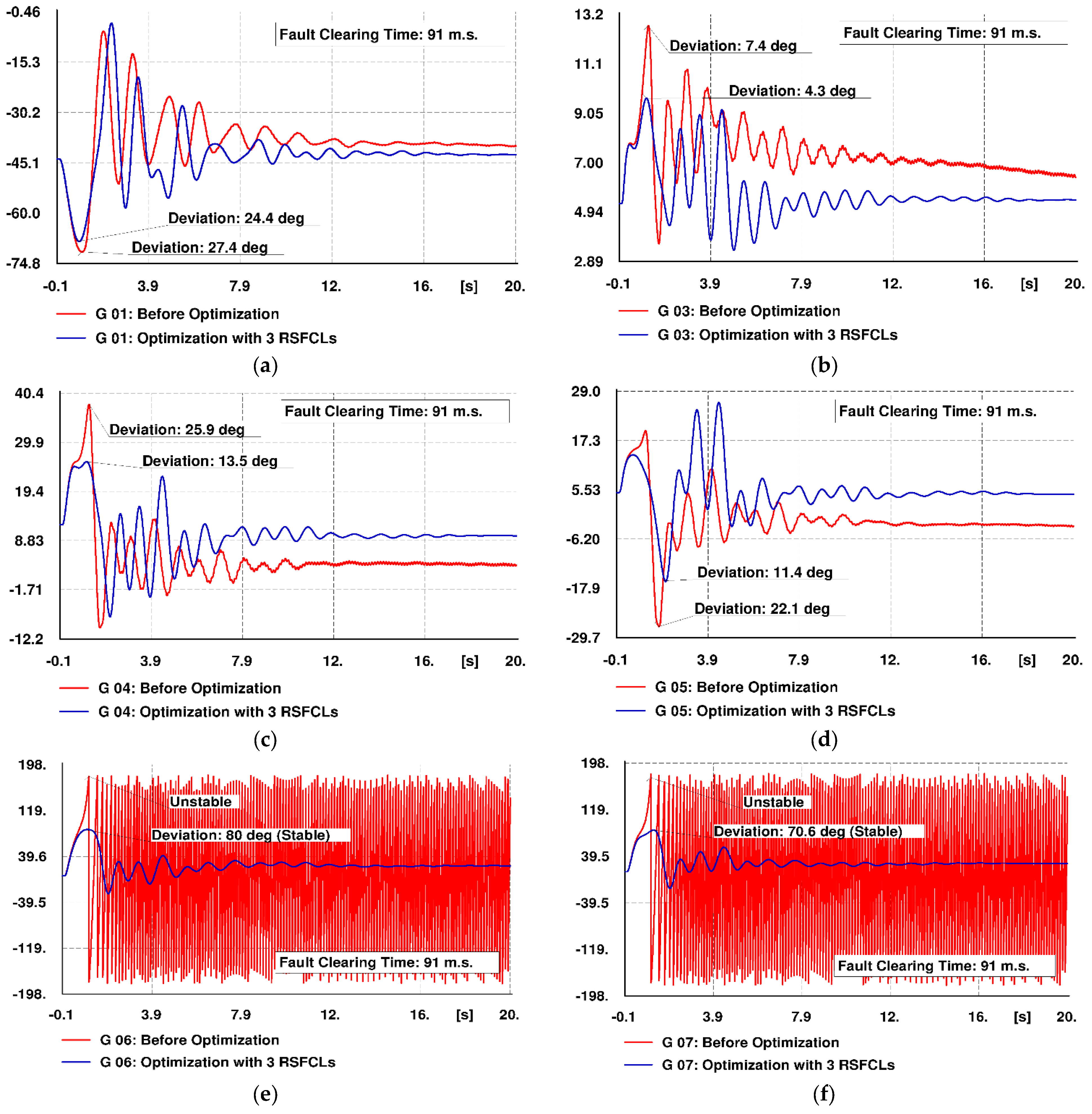
6.2. Improvement of Rotor Angle Deviations

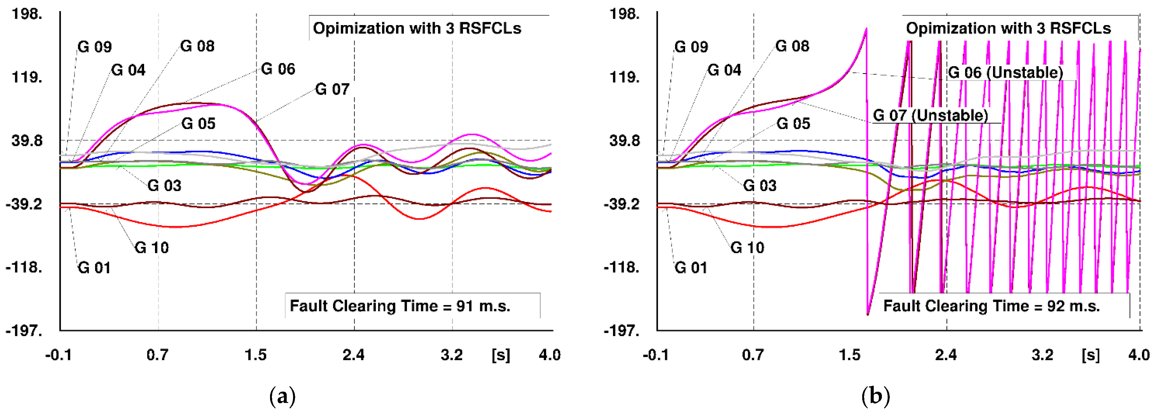
6.2.1. Scenario 1: Optimization of Three Candidate RSFCLs

Figure 13a–i illustrates the generators’ rotor angle deviations with reference to that of the reference machine. Red-colored curves depict the rotor angle oscillations before optimization, while the blue-colored curves represent the rotor angle oscillations in the presence of optimized RSFCLs. The curves depict a reduction in the maximum deviation of the rotor angles in the case of employing optimization results. Moreover, optimized RSFCLs have made the generators G6 and G7 stable.

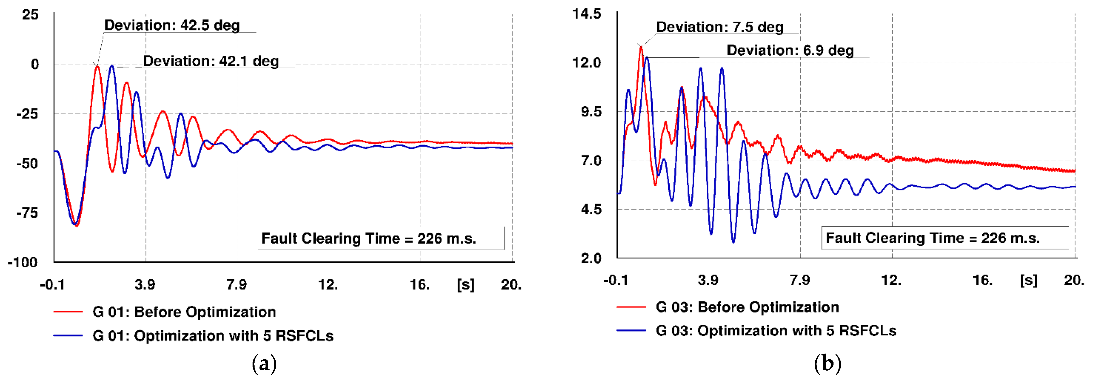
6.2.2. Optimization of 5 Candidate RSFCLs

The rotor angles of generators with reference to that of the reference machine are illustrated in Figure 14a–i. Red and blue colored lines show the rotor angle oscillations without and with employing the RSFCLs, respectively. Oscillation curves besides the stability of generators G6 and G7 reveal a reduction in the rotor angle deviations in the presence of optimized RSFCLs.
Table 5 compares the generators’ maximum rotor angle deviations for the considered three-phase short-circuit fault in both scenarios. It is observed that, besides the good improvement of CCT as discussed in the previous sub-section, a reduction in rotor angle deviations of generators has resulted, as a consequence of employing optimized RSFCLs. This reduction in rotor angle deviations can also be interpreted as an improvement in the transient stability of the power system.

7. Conclusions

In this paper, an approach was proposed based on the particle swarm optimization (PSO) algorithm for the optimal sizing and allocation of resistive-type superconducting fault current limiters (RSFCL) in order to improve the transient stability of power systems in the event of a three-phase short-circuit fault. To solve the optimization problem, an optimization approach was presented based on PSO, taking into account the objective function, optimization variables, and related constraints. The proposed algorithm was then coded in MATLAB. The efficiency of the proposed optimization algorithm was evaluated by numerical studies on the IEEE 39-bus New England system. Two scenarios were considered, including optimal sizing and the allocation of three and five RSFCLs. Optimization results were then simulated in DIgSILENT Power Factory demonstrating that, in the case of employing RSFCLs with sizes and locations resulting from the proposed optimization algorithm, the transient stability of the power system was noticeably improved, in view of increasing the critical clearing time (CCT), as well as the reduction of generators’ rotor angle deviations. For the considered short-circuit fault, the CCT was improved by 11 m.s. for three optimized RSFCLs, while its improvement for five optimized RSFCLs was 146 m.s., revealing a distinct better improvement of transient stability in the case of employing five optimized RSFCLs. In addition, simulation results depicted a reduction in the maximum deviation of the generators’ rotor angles in both scenarios. In order to continue and advance the results of this paper, investigating the impact of different short-circuit faults, as well as taking into account the economic aspects of RSFCLs in the objective function and optimizing the number of RSFCLs besides their sizes and locations, would be worthwhile issues for future research.

Author Contributions

Conceptualization, M.K.; methodology, M.K.; software, M.K.; validation, S.J.; formal analysis, A.H. and W.H.; investigation, M.K. and S.J.; resources, A.H.; data curation, M.K.; writing—original draft preparation, M.K.; writing—review and editing, M.K. and W.H.; visualization, M.K. and A.H.; supervision, S.J.; All authors have read and agreed to the published version of the manuscript.

Funding

This research received no external funding.

Conflicts of Interest

The authors declare no conflict of interest.

Nomenclature

  • Abbreviations
FCLFault current limiter
SFCLSuperconducting fault current limiter
RSFCLResistive-type superconducting fault current limiter
CCTCritical fault clearing time
PSOParticle swarm optimization
FCTFault clearing time
p.u.Per unit
B.
Indices and sets
NGSet of generation buses
NBSet of power system buses
NLSet of power system loads
NCRSet of candidate RSFCLs
C L R S F C L Set of locations for candidate RSFCLs
S C R Set of size decision variables (continuous variables)
L C R Set of location decision variables (integers)
NnsgSet of non-slack generators
jIndex of non-slack generators
XSet of decision variables, X   =   [ S C R ,   L C R ]
iIndex of buses
C.
Parameters and variables
δRotor angle of generator in electrical radians
PmMechanical power input of generator in p.u.
PeElectrical power output of generator in p.u.
HInertia constant of generator in MW-s/MVA
ω0Nominal speed of generator in electrical radian/s
OFObjective function
δj(t)Rotor angle magnitude of the jth generator at time t with reference to the slack generator
nNumber of generators in the power system
GSLSlack bus generator (reference machine)
CRNumber of candidate RSFCLs to be optimized
P G i ,   Q G i Generated active power (MW) and reactive power (MVAR) at bus i
P L i ,   Q L i Active (MW) and reactive (MVAR) loads at bus i
P G i min   ,   Q G i min Minimum active power (MW) and reactive power (MVAR) of generator i
P G i max   ,   Q G i max Maximum active power (MW) and reactive power (MVAR) of generator i
| V i |     ,     θ i Voltage magnitude (p.u.) and angle (degree) of bus i
| V j |     ,     θ j Voltage magnitude (p.u.) and angle (degree) of bus j
  θ   r e f Voltage angle (degree) of the reference bus
| Y i j |     ,     φ i j Admittance Amplitude (p.u.) and angle (degree) of line between buses i and j
  S R S F C L , k Value of candidate RSFCLs (p.u.)
S R S F C L ,   k max Maximum value of candidate RSFCL (p.u.)
L R S F C L , k Location of the candidate RSFCLs
ψ Inertia weight in the PSO
r1Cognitive factor
r2Social factor
CConstriction factor
C1, C2Acceleration constants
v i ( t ) Current velocity of the ith particle
v i ( t + 1 ) Next velocity of the ith particle
x i ( t ) Current position of the ith particle
x i ( t + 1 ) Next position of the ith particle
RmThe maximum resistance that the RSFCL can inject into the power system (p.u.)
TScThe time of transition from the superconducting state to the normal state in the RSFCL

References

  1. Hussain, A.; Kim, C.-H.; Mehdi, A. A Comprehensive Review of Intelligent Islanding Schemes and Feature Selection Techniques for Distributed Generation System. IEEE Access 2021, 9, 146603–146624. [Google Scholar] [CrossRef]
  2. Mehdi, A.; Kim, C.-H.; Hussain, A.; Kim, J.-S.; Jarjees Ul Hassan, S. A comprehensive review of auto-reclosing schemes in AC, DC, and hybrid (AC/DC) transmission lines. IEEE Access 2021, 9, 74325–74342. [Google Scholar] [CrossRef]
  3. Safaei, A.; Zolfaghari, M.; Gilvanejad, M.; Gharehpetian, G.B. A survey on fault current limiters: Development and technical aspects. Int. J. Electr. Power Energy Syst. 2020, 118, 105729. [Google Scholar] [CrossRef]
  4. Superconducting Fault Current Limiters: Technology Watch; EPRI: Palo Alto, CA, USA, 2009.
  5. Schmitt, H. Fault current limiters report on the activities of CIGRE WG A3.16. In Proceedings of the 2006 IEEE Power Engineering Society General Meeting, Montreal, QC, Canada, 18–22 June 2006. [Google Scholar] [CrossRef]
  6. Hussain, A.; Kim, C.-H.; Admasie, S. An intelligent islanding detection of distribution networks with synchronous machine DG using ensemble learning and canonical methods. IET Gener. Transm. Distrib. 2021, 23, 3242–3255. [Google Scholar] [CrossRef]
  7. Hooshyar, H.; Heydari, H.; Savaghebi, M.; Sharifi, R.; Shahbazi, B. An investigation on optimum volume of superconducting element of RSFCL considering harmonic generation. In Proceedings of the 2008 3rd IEEE Conference on Industrial Electronics and Applications, Singapore, 3–5 June 2008. [Google Scholar] [CrossRef] [Green Version]
  8. Haider, W.; Hassan, S.J.U.; Mehdi, A.; Hussain, A.; Adjayeng, G.O.M.; Kim, C.-H. Voltage Profile Enhancement and Loss Minimization Using Optimal Placement and Sizing of Distributed Generation in Reconfigured Network. Machines 2021, 9, 20. [Google Scholar] [CrossRef]
  9. Hooshyar, H.; Savaghebi, M. RSFCL optimum shunt resistance determination to enhance power system transient stability. In Proceedings of the 2008 43rd International Universities Power Engineering Conference, Padua, Italy, 1–4 September 2008. [Google Scholar] [CrossRef]
  10. Hongesombut, K.; Mitani, Y.; Tsuji, K. Optimal location assignment and design of superconducting fault current limiters applied to loop power systems. IEEE Trans. Appl. Supercond. 2003, 13, 1828–1831. [Google Scholar] [CrossRef]
  11. Sung, B.C.; Park, J.-W. Study on a series resistive SFCL to improve power system transient stability: Modelig, Simulation, and Experimental verification. IEEE Trans. Ind. Electron. 2009, 56, 2412–2419. [Google Scholar] [CrossRef]
  12. Yagami, M.; Shibata, S.; Murata, T.; Tamura, J. Improvement of power system transient stability by superconducting fault current limiter. In Proceedings of the IEEE/PES Transmission and Distribution Conference and Exhibition, Yokohama, Japan, 6–10 October 2002; Volume 1, pp. 359–364. [Google Scholar] [CrossRef]
  13. Tsuda, M.; Mitani, Y.; Tsuji, K.; Kakihana, K. Application of resistor based superconducting fault current limiter to enhancement of power system transient stability. IEEE Trans. Appl. Supercond. 2001, 11, 2122–2125. [Google Scholar] [CrossRef] [Green Version]
  14. Emhemed, A.S.; Tumilty, R.M.; Singh, N.K.; Burt, G.M.; McDonald, J.R. Analysis of Transient Stability Enhancement of LV-Connected Induction Microgenerators by Using Resistive-Type Fault Current Limiters. IEEE Trans. Power Syst. 2010, 25, 885–893. [Google Scholar] [CrossRef]
  15. Sadi, M.A.H.; Ali, M.H. Combined operation of SFCL and optimal reclosing of circuit breakers for power system transient stability enhancement. In Proceedings of the 2013 Proceedings of IEEE Southeastcon, Jacksonville, FL, USA, 4–7 April 2013; pp. 1–6. [Google Scholar] [CrossRef]
  16. Tephiruk, N.; Hongesombut, K.; Kerdphol, T. Robust control of combined optimized resistive FCL and ECS for power system transient stability improvement. In Proceedings of the 2014 International Electrical Engineering Congress (iEECON), Chonburi, Thailand, 19–21 March 2014. [Google Scholar] [CrossRef]
  17. Rao, M.U.M.; Rosalina, K.M. Improvement of transient stability in micro grids using RSFCL with series active power filter. SN Appl. Sci. 2019, 1, 1633. [Google Scholar] [CrossRef] [Green Version]
  18. Tariverdi, F.; Doroudi, A. Selection of Resistive and Inductive Superconductor Fault Current Limiters Location Considering System Transient Stability. J. Electr. Power Energy Convers. Syst. (JEPECS) 2016, 1, 72–78. [Google Scholar]
  19. Didier, G.; Bonnard, C.; Lubin, T.; Lévêque, J. Comparison between inductive and resistive SFCL in terms of current limitation and power system transient stability. Electr. Power Syst. Res. 2015, 125, 150–158. [Google Scholar] [CrossRef] [Green Version]
  20. Didier, G.; Lévêque, J.; Rezzoug, A. A novel approach to determine the optimal location of SFCL in electric power grid to improve power system stability. IEEE Trans. Power Syst. 2013, 28, 978–984. [Google Scholar] [CrossRef]
  21. Khatibi, M.; Bigdeli, M. Transient Stability Improvement of Power Systems by Optimal Sizing and Allocation of Resistive Superconducting Fault Current Limiters Using Particle Swarm Optimization. Adv. Energy Int. J. 2014, 1, 11–27. [Google Scholar]
  22. Saadat, H. Power System Analysis, 3rd ed.PSA publishing LLC: Alexandria, VA, USA, 2011. [Google Scholar]
  23. DIgSILENT GmbH, Heinrich-Hertz-Str. 9, 72810 Gomaringen, Germany. Available online: www.digsilent.de (accessed on 23 March 2021).
  24. Arman Safaei, M.Z.; Gilvanejad, M. A Strategic Plan for Implementation of Fault Current Limiters in Iran’s Power Grid; Niroo Research Institute: Tehran, Iran, 2018. [Google Scholar]
  25. Noe, M.; Steurer, M. High-temperature superconductor fault current limiters: Concepts, applications, and development status. Supercond. Sci. Technol. 2007, 20, R15. [Google Scholar] [CrossRef]
  26. Kalinov, A.V.; Voloshin, I.F.; Fisher, L.M. SPICE model of high-temperature superconducting tape: Application to resistive fault-current limiter. Supercond. Sci. Technol. 2017, 30, 054002. [Google Scholar] [CrossRef]
  27. Zhang, X. Resistive-Type Superconducting Fault Current Limiter (RSFCL) and Its Application in Power Systems. Ph.D. Thesis, Churchill College University of Cambridge, Cambridge, UK, 2017. [Google Scholar]
  28. Ruiz, H.S.; Zhang, X.; Coombs, T.A. Resistive-Type Superconducting Fault Current Limiters: Concepts, Materials, and Numerical Modeling. IEEE Trans. Appl. Supercond. 2015, 25, 1–5. [Google Scholar] [CrossRef] [Green Version]
  29. Mafra, G.R.F.Q.; Sotelo, G.G.; Fortes, M.Z.; de Sousa, W.T.B. Application of resistive superconducting fault current limiters in offshore oil production platforms. Electr. Power Syst. Res. 2016, 144, 107–114. [Google Scholar] [CrossRef]
  30. Okakwu, P.; Orukpe, E.; Ogujor, E.A. Apolication of Superconducting Fault Current Limiter (SFCL) in Power Systems: A review. EJERS Eur. J. Eng. Res. Sci. 2018, 3, 28–32. [Google Scholar] [CrossRef]
  31. Hooshyar, H.; Heydari, H.; Savaghebi, M.; Sharifi, R. Resistor Type Superconducting Fault Current Limiter: Optimum Shunt Resistance Determination to Enhance Power System Transient Stability. IEEJ Trans. Power Energy 2009, 129, 299–308. [Google Scholar] [CrossRef] [Green Version]
  32. Morandi, A. State of the art of superconducting fault current limiters and their application to the electric power system. Phys. C Supercond. 2013, 484, 242–247. [Google Scholar] [CrossRef]
  33. Kalsi, S.S.; Malozemoff, A. HTS Fault Current Limiter Concept. IEEE Trans. Appl. Supercond. 2004, 2, 1426–1430. [Google Scholar]
  34. Mandic, M.; Juric-Grgic, I.; Grulovic-Plavljanic, N. Improving time integration scheme for FET analysis of power system angle stability. Electron. Energetics 2020, 33, 119–131. [Google Scholar] [CrossRef] [Green Version]
  35. Radan, M.; Dinan, A.T. Power System Transient Stability Analysis Based on the Development and Evaluation Methods. Int. J. Smart Electr. Eng. 2016, 5, 169–173. [Google Scholar]
  36. Odun-Ayo, T.; Crow, M.L. An analysis of power system transient stability using stochastic energy functions. Int. Trans. Electr. Energy Syst. 2013, 23, 151–165. [Google Scholar] [CrossRef]
  37. Ferraro, R.M. Method of Modeling the Swing Equation Using Time Synchronized. Master’s Thesis, Portland State University, Portland, OR, USA, 2021. Paper 5729. [Google Scholar] [CrossRef]
  38. Kundur, P. Power System Stability and Control; McGraw Hill: New York, NY, USA, 1994. [Google Scholar]
  39. Messalti, S.; Belkhiat, S. Comparative Study of Resistive and Inductive Superconducting Fault Current Limiters SFCL for Power System Transient Stability Improvement. J. Supercond. Nov. Magn. 2013, 26, 3009–3015. [Google Scholar] [CrossRef]
  40. Sengupta, S.; Basak, S.; Peters, R.A. Particle Swarm Optimization: A Survey of Historical and Recent Developments with Hybridization Perspectives. Mach. Learn. Knowl. Extr. 2018, 1, 157–191. [Google Scholar] [CrossRef]
  41. Kennedy, J.; Eberhart, R.C. Particle Swarm Optimization. In Proceedings of the ICNN’95—International Conference on Neural Networks, Perth, WA, Australia, 27 November—1 December 1995; pp. 1942–1948. [Google Scholar]
  42. Hu, X.; Eberhart, R. Solving Constrained Nonlinear Optimization Problem with Particle Swarm Optimization; Purdue University: West Lafayette, IN, USA, 2002. [Google Scholar]
  43. Clerc, M. Particle Swarm Optimization; Antony Rowe Ltd Publication: Chippenham, UK, 2006. [Google Scholar]
  44. Pai, M.A. Energy Function Analysis for Power System Stability; Kluwer Academic Publishers: Boston, MA, USA, 1989; pp. 223–227. [Google Scholar]
  45. Priyadi, A.; Sari, T.P.; Dwi S., W.; Yorino, N.; Purnomo, M.H. Determining Critical Clearing Time Based on Critical Trajectory Method using Unbalance Fault. In Proceedings of the 2019 International Seminar on Intelligent Technology and Its Applications (ISITIA), Surabaya, Indonesia, 28–29 August 2019. [Google Scholar] [CrossRef]
  46. Determining Generator Fault Clearing Time for the Synchronous Zone of Continental Europe; RG-CE System Protection & Dynamics Sub Group: Brussels, Belgium, 2017; Available online: www.entsoe.eu (accessed on 29 June 2020).
  47. Kastinen, P.; Fuengwarodsakul, N.; Wangdee, W. Investigation of Critical Fault Clearing Time by Applying Different Excitation System Models. In Proceedings of the 2019 Research, Invention, and Innovation Congress (RI2C), Bangkok, Thailand, 11–13 December 2019. [Google Scholar] [CrossRef]
  48. Sharma, S.; Pushpak, S.; Chinde, V.; Dobson, I. Sensitivity of Transient Stability Critical Clearing Time. IEEE Trans. Power Syst. 2018, 33, 6476–6486. [Google Scholar] [CrossRef]
  49. Ghani, A.M. Improving Stability by Enhancing Critical Fault Clearing Time. Master’s Thesis, University of South Florida, Tampa, FL, USA, 2019. Available online: https://scholarcommons.usf.edu/etd/7793 (accessed on 28 April 2021).
Figure 1. (a) The schematic of a RSFCL [29]; (b) a practical installation of SFCL [30].
Electronics 11 03980 g001
Figure 2. Simple model of a RSFCL in a SMIB system.
Electronics 11 03980 g002
Figure 3. Possible applications of SFCLs in the power system [32].
Electronics 11 03980 g003
Figure 4. The δ oscillation curve of a generator at time interval of (0 − T) and its corresponding area.
Electronics 11 03980 g004
Figure 5. Structure of a typical PSO particle for the proposed problem.
Electronics 11 03980 g005
Figure 6. Optimization procedure of RSFCLs sizing and allocation using PSO.
Electronics 11 03980 g006
Figure 7. Single-line diagram of 39-bus New England system.
Electronics 11 03980 g007
Figure 8. Convergence curve of PSO for the proposed objective function. (a) Scenario 1 (3 RSFCLs), (b) Scenario 2 (5 RSFCLs).
Electronics 11 03980 g008
Figure 9. Locations of RSFCLs; blue-colored arrows: Scenario 1; green-colored arrows: Scenario 2.
Electronics 11 03980 g009
Figure 10. CCT of the system before optimization (for the considered short-circuit fault). (a) FCT = 80 m.s. (stable), (b) FCT = 81 m.s. (unstable).
Electronics 11 03980 g010
Figure 11. CCT in Scenario 1 (3 RSFCLs) for the considered short-circuit fault. (a) FCT = 91 m.s. (stable), (b) FCT = 92 m.s. (unstable).
Electronics 11 03980 g011
Figure 12. CCT in Scenario 2 (5 RSFCLs) for the considered short-circuit fault. (a) FCT = 226 m.s. (stable), (b) FCT = 227 m.s. (unstable).
Electronics 11 03980 g012
Figure 13. Rotor angle oscillation of generators in Scenario 1 with reference to the reference machine “with” and “without” optimized RSFCLs. (a) Generator G1, (b) Generator G3, (c) Generator G4, (d) Generator G5, (e) Generator G6, (f) Generator G7, (g) Generator G8, (h) Generator G9, (i) Generator G10.
Electronics 11 03980 g013aElectronics 11 03980 g013b
Figure 14. Rotor angle oscillation of generators in Scenario 2 with reference to the reference machine “with” and “without” optimized RSFCLs. (a) Generator G1, (b) Generator G3, (c) Generator G4, (d) Generator G5, (e) Generator G6, (f) Generator G7, (g) Generator G8, (h) Generator G9, (i) Generator G10.
Electronics 11 03980 g014aElectronics 11 03980 g014b
Table 1. PSO setting data for the considered optimization problem.
ItemNumber of Iterations:Swarm Size:PSO Setting Parameters:Bounds of Variables
C1C2CLocationSize
Value1000402.052.050.85(1–46)(0–0.025)
Table 2. Characteristics of the considered fault.
ItemValue
Fault typeSymmetrical three-phase
Fault locationLine (21–22), close to bus 22
Fault clearing time: 300 (m.s.)
Table 3. Optimization results of the 39-bus New England case study.
ScenarioRSFCL Location
(bus i–bus i’)
RSFCL Size
(p.u.)
Objective Function
Value
Scenario 1:
(3 RSFCLs)
(35–22)0.0138851939.500
(36–23)0.021661
(38–29)0.006964
Scenario 2:
(5 RSFCLs)
(35–22)0.0141381793.600
(36–23)0.023494
(20–19)0.024524
(12–11)0.021002
(39–9)0.005074
Table 4. CCT improvement in the investigated scenarios.
ScenarioWithout Employing RSFCLsScenario 1
(3 RSFCLs)
Scenario 2
(5 RSFCLs)
CCT (m.s.)8091226
Table 5. Comparison of generators’ maximum rotor angle deviations in both scenarios for the considered short-circuit fault.
Maximum Rotor Angle Deviation (Degrees)
Scenario 1 (3 RSFCLs)Scenario 2 (5 RSFCLs)
Generator
No.
Without
RSFCLs
With
RSFCLs
Without
RSFCLs
With
RSFCLs
G127.424.442.542.1
G37.44.37.56.9
G425.913.533.715.1
G522.111.431.623.5
G6Unstable80Unstable97.1
G7Unstable70.6Unstable80.4
G814.69.114.513.3
G922.114.325.623.9
G1012.84.714.413
Publisher’s Note: MDPI stays neutral with regard to jurisdictional claims in published maps and institutional affiliations.

